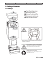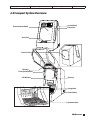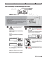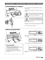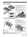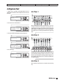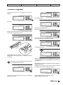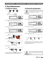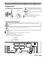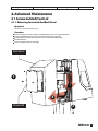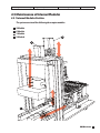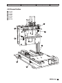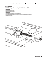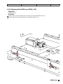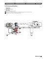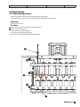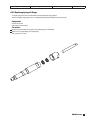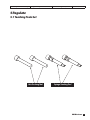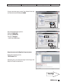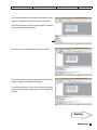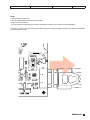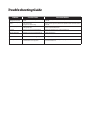
1
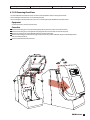
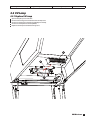
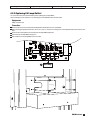
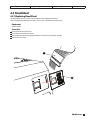
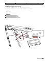
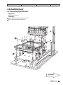
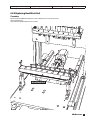
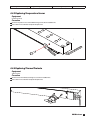
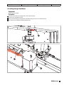
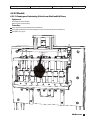
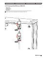
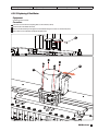
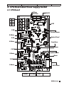
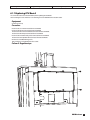
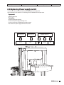
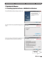
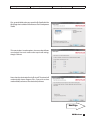
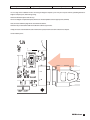
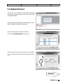
MagCore® Compact
Service Manual
Issued By: RBC Bioscience Corp.
MagCore Compact Service Manual
Revised: August. 12, 2011
V 2.0.2
Safety Precautions
Before use
These WARNINGS and CAUTIONS are intended to protect you and other persons from injuries and damages. To ensure safe operation, please follow them carefully.
SAFETY INSTRUCTIONS
CAUTIONS
Risk Of Electric Shock Do Not Open
CAUTION:
To Reduce The Risk Of Electric Shock, Do Not Remove Cover (Or Back).
No Userserviceable Parts Inside. Refer Servicing To Qualified Service Personnel.
The lightning flash with arrowhead symbol, within an equilateral
triangle, is intended to alert the user to the presence of uninsulated
“dangerous voltage” within the product’s enclosure that may
be of sufficient magnitude to constitute a risk of electric shock to
persons.
The exclamation point within an equilateral triangle isintended
to alert the user to the presence of important operating
and maintenance (servicing) instructions in the literature
accompanying the appliance.
Be aware of contaimination by contagious specimens.
High temperature warning!!
DO NOT touch the heating block with this sticker attached, it may
cause serious burning injuries.
CAUTION:
1. Handle the power supply cord carefully
Do not damage or deform the power supply cord. If it is damaged or deformed, it
may cause electric shock or malfunction when used. When removing from wall
outlet, be sure to remove by holding the plug attachment and not by pulling the
cord.
2. Do not open the top cover
In order to prevent electric shock, do not open the top cover.
3. Do not place anything inside
Do not place metal objects or spill liquid inside the MagCore® System. Electric shock
or malfunction may result.
Note On Use:
Avoid high temperatures.
Allow for sufficient heat dispersion when installed on a rack.
Handle the power cord carefully.
Hold the plug when unplugging the cord.
Keep the set free from moisture, water, and dust.
Unplug the power cord when not using the set for
long periods of time.
Do not obstruct the ventilation space.
Do not let insecticides, benzene, and thinner come in
contact with the set.
Never disassemble or modify the set in any way.
1. Read Instructions – All the safety and operating instructions should be read before the
product is operated.
2. Retain Instructions – The safety and operating instructions should be retained for future
reference.
3. Heed Warnings – All warnings on the product and in the operating instructions should be
adhered to.
4. Follow Instructions – All operating and use instructions should be followed.
5. Cleaning – Unplug this product from the wall outlet before cleaning. Only allow to use 75% of
EtOH to clean the surface of instrument.
6. Attachments – Do not use attachments not recommended by the product manufacturer as
they may cause hazards.
7. Water and Moisture – Do not use this product near water – for example, near a bath tub,
wash bowl, kitchen sink, or laundry tub; in a wet basement; or near a swimming pool; and the
like.
8. Accessories – Do not place this product on an unstable cart, stand, tripod, bracket, or
table. The product may fall, causing serious injury to a child or adult, and serious damage
to the product. Use only with a cart, stand, tripod, bracket, or table recommended by the
manufacturer, or sold with the product. Any mounting of the product should follow the
manufacturer’s instructions, and should use a mounting accessory recommended by the
manufacturer.
9. Ventilation – Slots and openings in the cabinet are provided for ventilation and to ensure
reliable operation of the product and to protect it from overheating, and these openings
must not be blocked or covered. The openings should never be blocked by placing the
product on a bed, sofa, rug, or other similar surface. This product should not be placed in a
built-in installation such as a bookcase or rack unless proper ventilation is provided or the
manufacturer’s instructions have been adhered to.
10.Power Sources – This product should be operated only from the type of power source
indicated on the marking label. If you are not sure of the type of power supply to your home,
consult your product dealer or local power company. For products intended to operate from
battery power, or other sources, refer to the operating instructions.
11.Grounding or Polarization – This product may be equipped with a polarized alternatingcurrent line plug (a plug having one blade wider than the other). This plug will fit into the
power outlet only one way. This is a safety feature. If you are unable to insert the plug fully
into the outlet, try reversing the plug. If the plug should still fail to fit, contact your electrician to
replace your obsolete outlet. Do not defeat the safety purpose of the polarized plug.
12.Power-Cord Protection – Power-supply cords should be routed so that they are not likely to
be walked on or pinched by items placed upon or against them, paying particular attention to
cords at plugs, convenience receptacles, and the point where they exit from the product.
13.Lightning – For added protection for this product during a lightning storm, or when it is left
unattended and unused for long periods of time, unplug it from the wall outlet and disconnect
the antenna or cable system. This will prevent damage to the product due to lightning and
power-line surges.
14.Overloading – Do not overload wall outlets, extension cords, or integral convenience
receptacles as this can result in a risk of fire or electric shock.
15.Object and Liquid Entry – Never push objects of any kind into this product through openings
as they may touch dangerous voltage points or short-out parts that could result in a fire or
electric shock. Never spill liquid of any kind on the product.
16.Servicing – Do not attempt to service this product yourself as opening or removing covers
may expose you to dangerous voltage or other hazards. Refer all servicing to qualified service
personnel.
17.Damage Requiring Service – Unplug this product from the wall outlet and refer servicing to
qualified service personnel under the following conditions:
a) When the power-supply cord or plug is damaged,
b) If liquid has been spilled, or objects have fallen into the product,
c) If the product has been exposed to rain or water,
d) If the product does not operate normally by following the operating instructions. Adjust
only those controls that are covered by the operating instructions as an improper adjustment
of other controls may result in damage and will often require extensive work by a qualified
technician to restore the product to its normal operation,
e) If the product has been dropped or damaged in any way, and
f) When the product exhibits a distinct change in performance
– this indicates a need for service.
18.Replacement Parts – When replacement parts are required, be sure the service technician
has used replacement parts specified by the manufacturer or have the same characteristics as
the original part. Unauthorized substitutions may result in fire, electric shock, or other hazards.
19.Safety Check – Upon completion of any service or repairs to this product, ask the service
technician to perform safety checks to determine that the product is in proper operating
condition.
20.Heat – The product should be situated away from heat sources such as radiators, heat
registers, stoves, or other products that produce heat.
Do not let foreign objects in the set.
RBCBioscience
1
Issued By: RBC Bioscience Corp.
MagCore Compact Service Manual
Revised: August. 12, 2011
V 2.0.2
Specification
Model
System Method
System
Components
Power Supply
Dimension
Net Weight
Compact
Cellulose coated magnetic beads
1. Pipetting Unit: Dispensing, transferring, X-Y two axis movements.
2. Electric Control: Internal microprocessor.
3. UV Light: Power 5W, life duration >1,000 Hrs.
4. Heating Block: RT~100°C.
5. Display Screen: 3 inches LCM Screen with keypress Panel
6. Accessories: T- Rack, Cartridge Rack , Empty Cartridges, Tip/Holders , Sample Tube, Microcentrifugr Tube, Syringe
O-ring and Grease.
Voltage: AC 100-240V; Frequency: 50/60Hz; Power Consumption >1.0KVA
W350 X D660 X H680 (mm)
W13.79 X D25.98 X H26.77 (inches)
50 kg / 110 lbs
Operating Paramenters
Processing Capacity
Processing Time
Sample Volume
Elution Volume
Yield
Purity
1~8 samples per batch
30-70 minutes (depends on sample type and method)
200μl /400μl /1,200μl
60μl /100μl /150μl /200 μl
Avrage 6μg Genomic DNA from 200μl human whole blood
O.D. 1.8-2.0 A260/280 ratio
Operating Environment
Temperatures allowed
during transportation
storage
packaging
Temperatures allowed
during
operation
Pollution Degree
15°C ~ 35°C
18°C to 30°C
Indoor
Applications
Whole Blood (200μl /400μl), Viral Nucleic Acid (DNA/RNA), Tissue Genomic , Plant Genomic DNA Bacteria, Cultured Cells, Total RNA, Large
volume whole blood (1,200μl )
RBCBioscience
2
Issued By: RBC Bioscience Corp.
MagCore Compact Service Manual
Revised: August. 12, 2011
V 2.0.2
Index
1.
Safety Precautions ......................................................................................................................................................... 1
Specification / Operating Paramenters / Operating Environment Aoolications .................................... 2
Package Contents .......................................................................................................................................................... 5
1.1
1.2
Package .................................................................................................................................................................................. 5
Accessories .............................................................................................................................................................................. 6
2.
Installation
2.1
2.2
2.3
2.4
2.5
2.6
2.7
2.8
2.8.1
2.8.2
2.8.2
2.9
....................................................................................................................................................................... 7
.........................................................................................................................................................................
7
Before Install
.........................................................................................................................................................
8
Compact System Overview
................................................................................................................................
9
LCM Display Screen and Keypress Panel
......................................................................................................................................................... 10
Install MagCore® Compact
...........................................................................................................................................................
10
Remove bump buffer
....................................................................................................................................................................
11
Insert Cartridge
Setup Tube, Tip and Tip Holder ........................................................................................................................................... 11
System Test .......................................................................................................................................................................... 12
Test1 ...................................................................................................................................................................................... 12
Test2 ...................................................................................................................................................................................... 12
Test3 ...................................................................................................................................................................................... 12
Start Programs ..................................................................................................................................................................... 13
3.
Easy Maintenance
3.1
3.2
3.3
3.3.1
3.3.2
Replace O-Rings ................................................................................................................................................................... 14
Clean Piercing Needles ......................................................................................................................................................... 14
Replace Fuse ......................................................................................................................................................................... 15
Replaxe Fuse (inside Power Inlet) .............................................................................................................................................. 15
Replaxe Fuse (CPU Board) ........................................................................................................................................................ 15
4.
Advanced Maintenance ............................................................................................................................................. 17
4.1
4.1.1
4.1.2
4.1.2.1
4.1.2.2
4.1.2.3
4.2
4.2.1
4.2.2
4.3
4.3.1
4.3.2
4.4
4.4.1
4.4.2
4.4.3
4.4.4
4.5
4.5.1
4.5.2
4.5.3
4.5.3.1
4.5.3.2
4.5.3.3
Service Lid And Front Lid .................................................................................................................................................... 17
Removing Service Lid And Back Panel ...................................................................................................................................... 17
Removing Front Door And Front Lid ......................................................................................................................................... 18
Removing Front Door Connectors ............................................................................................................................................ 18
Removing Front Lid ................................................................................................................................................................. 19
Removing Front Door ............................................................................................................................................................. 20
UV Lamp .............................................................................................................................................................................. 21
Replacing UV Lamp ................................................................................................................................................................ 21
Replacing UV Lamp Ballast ...................................................................................................................................................... 22
Panel Sheet ......................................................................................................................................................................... 23
Replacing Panel Sheet ............................................................................................................................................................ 23
Replacing Operation Panel ..................................................................................................................................................... 24
Heat Block Unit ................................................................................................................................................................... 25
Removing Tip Holder Unit ....................................................................................................................................................... 25
Replacing Heat Block Unit ....................................................................................................................................................... 26
Replacing Temperature Sensor ................................................................................................................................................ 27
Remove Thermal protecto ....................................................................................................................................................... 27
Maintenance of Internal Modules ..................................................................................................................................... 28
Internal Modules Position......................................................................................................................................................... 28
Sensor Position ........................................................................................................................................................................ 29
X Module ................................................................................................................................................................................ 30
Cleaning and Lubricating X Axis LM Guides and Ball ................................................................................................................. 30
Replacing X Axis ORG Sensor (XORG, + XEL) .............................................................................................................................. 31
Replacing X Axis Motor ............................................................................................................................................................ 32
........................................................................................................................................................ 14
RBCBioscience
3
Issued By: RBC Bioscience Corp.
4.5.4
4.5.4.1
4.5.4.2
4.5.4.3
4.5.4.5
4.5.5
4.5.5.1
4.5.5.2
4.5.5.3
4.5.6
4.5.6.1
4.5.6.2
4.5.6.3
4.5.6.4
4.5.6.5
4.6
4.6.1
4.6.2
MagCore Compact Service Manual
Revised: August. 12, 2011
V 2.0.2
Y Module ................................................................................................................................................................................ 33
Remove Electronic Control Board ............................................................................................................................................ 33
Cleaning and Lubricating Y Axis Ball Screw ............................................................................................................................... 34
Replacing Y Axis ORG Sensor (YORG, + YEL) .............................................................................................................................. 35
Replacing Y Axis Motor ........................................................................................................................................................... 36
V Module ................................................................................................................................................................................ 37
Cleaning and Lubricating V Axis Ball Screw ............................................................................................................................... 37
Replacing V Axis ORG Sensor (YORG, + YEL) .............................................................................................................................. 38
Replacing V Axis Motor ............................................................................................................................................................ 39
E Module ................................................................................................................................................................................ 40
Replacing magnet Unit ............................................................................................................................................................ 40
Removing E Axis Shaft Unit ...................................................................................................................................................... 41
Replacing E Axis Timing Belt ..................................................................................................................................................... 42
Replacing E Axis ORG Sensor (EORG) ........................................................................................................................................ 43
Replacing E Axis Motor ............................................................................................................................................................ 44
Single Syringe ......................................................................................................................................................................... 45
Replacing Single Syringe .......................................................................................................................................................... 45
Replacing Syringe O-Rings ...................................................................................................................................................... 46
5.
Regulate ........................................................................................................................................................................... 47
5.1
5.2
5.3
Teaching Tools Set ................................................................................................................................................................... 47
Procedures before Calibration .................................................................................................................................................. 48
Setting Yaxis and X Axis process Position ................................................................................................................................... 51
6.
CPU Board and Power Supply Switch ..................................................................................................................... 52
6.1
6.1.1
6.2
CPU Board Overview ............................................................................................................................................................... 52
Replacing CPU Board .............................................................................................................................................................. 53
Replacing Power Switch .......................................................................................................................................................... 54
7.
Software Update ........................................................................................................................................................... 55
7.1
7.2
Install magCore Update Software- RENESAS For Windows ........................................................................................................ 55
Update protocol ..................................................................................................................................................................... 59
Trouble Shooting Guide
Attachment
RBCBioscience
4
Issued By: RBC Bioscience Corp.
MagCore Compact Service Manual
Revised: August. 12, 2011
V 2.0.2
1. Package Contents
1.1 Package
1
2
Open the package cover.
Remove accessories.
Remove the bump buffer.
Remove outer carton case.
Take out of the machine .
3
4
5
5
MagCore®Compact has a weight of 70 kg(155lb). 2 people are required to lift
the MagCore® Compact safely.
Please put MagCore® Compact on a solid worktop table
without pulley. Do not place on the same table of other
facilities which need to be kept away from vibration.
Packaging materials are recyclable.
Recommends to keep the package for future
transportation or movement.
RBCBioscience
5
Issued By: RBC Bioscience Corp.
MagCore Compact Service Manual
Revised: August. 12, 2011
V 2.0.2
1.2 Accessories
Check that the following parts are included in addition to the main unit:
T-Rack..........................................................1
Cartridge Rack........................................1
Power Cable.............................................1
Lubricating silicon grease..................1
O-Rings......................................8
Cartridge...................................32
Sample/Elution Tube........................32
Tip/Tip Holder.......................................32
Accessory No: 6, 7, 8 are installation tools, please keep clean for permanent use.
1.3 Engineer Tools
Axis Teaching Tools..............................2
Syringe Teaching Tools............................2
RS232 To USB Converters.......................1
Program CD ........................................1
RBCBioscience
6
Issued By: RBC Bioscience Corp.
MagCore Compact Service Manual
Revised: August. 12, 2011
V 2.0.2
2. Installation
2.1 Before Install
120cm
30cm
5cm
Before installation, please find a location of bench-top close to electrical outlets, and remain
enough space for machine installation and ventilation.
RBCBioscience
7
Issued By: RBC Bioscience Corp.
MagCore Compact Service Manual
Revised: August. 12, 2011
V 2.0.2
2.2 Compact System Overview
Protective Acryl Board
Control Panel
Front Door
Door Pull
Service Lid
UV Lamp
Door-Open Detector
LCD Window
Door Pry
Syringe Unit
Power Switch
Operation Area
RBCBioscience
8
Issued By: RBC Bioscience Corp.
MagCore Compact Service Manual
Revised: August. 12, 2011
V 2.0.2
2.3 LCM Display Screen and Keypress Panel
Error LED
UV Key
Indicator LED
Start Key
STOP Key / Emergent Key
LCM Display Screen
MagCore® Compact provides a touch button keypress panel for you to
communicate with your instrument. The number keys give users to input
Cartridge Code which specified on the Reagent Cartridge to run built-in
program automatically, or to select desired volumes at start-up sample
and final elution steps.
LCM Display Screen which with sapphire background light, shows clear
information that the MagCore® Compact is currently performing.
Special function of buttons described as:
Perform UV sterilization after
handling contagious specimens.
UV Sterilization
UV button is designed to turn on UV Lamp while your
MagCore® Compact needs to be sterilized after runing
contagious samples.
Procedure
Turn on power switch of MagCore® Compact, or after
program completed and return back to “Stand-By”
condition.
LCM display screen shows “ Stand-By” .
MAGCORE Compact
STAND-BY
PRESS<START>TO
RUN
Emergent Stop
Stop button is designed for going
back to “Stand-By” menu at program
completed, or for EMERGENT STOP
use.
In case of emergency, press “STOP” button at anytime.
LCM display screen shows warning sign, Red Indicate
LCD lights up and a beep sound can be heard.
EMERGENT
STOP
<START> CONTINUE
<ESC> ABOUT
If the front door was opened during
program running, MagCore®
Compact stops all mechanical
movements immediately due to safty
considerations.
UV LIGHT
<1>1hr <2>30min
<ESC>To
Back
Press UV button to proceed UV sterilization with 1hr /
30 mins of time options.
Esc: Back to “Stand-By” menu.
Shift button is designed for machine calibration
DO NOT excute this program without trained
engineer aside.
UV lamp actives and count down with selected time
at minutes.
MagCore® Compact will go back to “ Stand-By”
menu once UV sterilization procedure completed.
RBCBioscience
9
Issued By: RBC Bioscience Corp.
MagCore Compact Service Manual
Revised: August. 12, 2011
V 2.0.2
2.4 Install MagCore® Compact
Proceed installation procedures after placing MagCore® Compact on
a solid bench-top.
Open the front door and use philip screw driver to loose and take out
the L-Block.
Please retain the L-Block and screws, to relocate for
future move process or to fixed machine .
Confirm the outlet voltage is 100v to 240v Keep
hands dry and make sure that the machine remain
switch-off while insert into the socket then turn on
the power switch.
Connect power socket and turn on the power.
2.5 Remove bump buffer
MAGCORE Compact
STAND-BY
PRESS<START>TO
RUN
After power on, LCM shows " STAND-BY", then press Shift for
FUNCTION menu
<1>CLEAN
<5>HEATER
<2>PISTON <6>TIP
<3>SENSOR
<4>MOTOR <ESC>BACK
Select (2) PISTION, machine will retreat bump buffer automatically.
Repack bump buffer
1. Plug in power cable, then turn on power switch.
2. Push back the plateform back (without T-rack and cartridge
rack) to position where L-Block can be fixed.
3. Use Philip screw drive to fix 4 screws to L-Block.
4. Place the bump buffer on the cartridge plateform
5. Pull down the Syrindge plateform to secure bump buffer.
6. Turn off power.
MAGCORE Compact
STAND-BY
PRESS<START>TO
RUN
Press ECS twice to go back to STAND-BY menu. Complete instal
procedures.
RBCBioscience
10
Issued By: RBC Bioscience Corp.
MagCore Compact Service Manual
Revised: August. 12, 2011
V 2.0.2
2.6 Insert Cartridge
Insert MagCore® Compact Viral Nucleic Acid cartridge into
Cartridge Rack following arrow point directions.
A. Slide MagCore® Compact cartridge into Cartridge Rack to the
end with slight downward angle.
B. Press down the cartridge to interlock position under the overhang part of Cartidge Rack. A click sound can be heard when it is
locked correctly.
Load as many cartridges as sample runs. Capacity for each
Cartridge Rack is 8, up to 16 samples for two Cartridge Racks can
be performed at one time on MagCore® Compact.
Instal the cartridges loaded Cartridge Rack into inner operation
area of the MagCore® Compact and lock firmly.
A
B
2.7 Setup Tube, Tip and Tip Holder
Well 1
Well 2
Well 3
Well 4
Put Tips into Tip Holders.
Set the Tip/Tip Holder onto hole 2 of T-Rack.
Place provided Elution (Eppendorf) Tube or other types of tube into
hole 1 of T-Rack as final purified DNA collection tube.
Set the Sample Tube onto hole 4 of T-Rack.
Instal the Tip/Holder and Sample/Elution Tubes loaded T-Rack into
outter operation area of the MagCore® Compact and lock firmly.
Elution Tube
Tip / Tip Holder
Sample Tube
Please refer to MagCore® Kit User Menu for appropriate wells
to setup Tip and Tube.
Caution:
DO NOT use any other type of microcentrifuge tube to replace provided Sample Tube.
It may cause operation impact due to different height of tubes.
RBCBioscience
11
Issued By: RBC Bioscience Corp.
MagCore Compact Service Manual
Revised: August. 12, 2011
V 2.0.2
2.8 System Test
1. Apply 16 Tips / Tip Holders and Sample/Elution Tubes to
T-Rack. Add 1ml of water to each Sample Tubes then close the
front door.
MAGCORE
2.8.1Test 1
Compact
STAND-BY
PRESS<START>TO
RUN
2. Press Shift to enter FUNCTION Menu.
<1>CLEAN
<2>PISTON
<3>SENSOR
<5>HEATER
<6>TIP
<4>MOTOR
<ESC>BACK
Machine taking up Tips, please check whether the Tips move
smoothly. If you observe a Tip Holder stuck, please press the
STOP button immediately to stop and remove the jammed
Holder. Replace the Tip/Tip Holder then run the procedure again.
If the problem persists, contact your local dealer for engineering
helps.
3. Select (2) PISTON for Tip taking and Syringe air-tight tests.
2.8.2 Test 2
Initializing
PISTON TEST
LOAD>TIP/HOLDER
>TUBE
<START>GO
WITH WATER
<ESC>BACK
4. Press START to go.
TIP<2>
TAKING
000min
Tip will absorb water from Sample Tube and pause for 15
seconds, please check the liquid level of each columns are at
same horizontal. If leakage situation is observed, press STOP
button to stop and replcae the leaking Tip and O-ring, then run
the test again. If the problem persists, contact your local dealer
for engineering helps.
2.8.3 Test 3
Return Tip Please check whether it is smooth or not at returning
Tips.
RBCBioscience
12
Issued By: RBC Bioscience Corp.
MagCore Compact Service Manual
Revised: August. 12, 2011
V 2.0.2
2.9 Start Programs
Install all necessary accessories and apply your specimen to
MagCore®.
VIRAL NA OOO/OOO
SELECT SAMPLE VOLUME
(1)OOOul (2)OOOul
(ESC) PREV PAGE
MAGCORE Compact
STAND-BY
PRESS<START>
TO
RUN
Select Sample Volume.
Press START
CARTRIDGE
OOO...
(Enter)
(ESC)
Initializing
NEXT
OOO
PAGE
CANCEL
Confirm your input Sample Volume.
Press Enter for next page, Press ESC for back to Stand-By page.
After press Start button, machine runs program of calibration, initialize
to move all axis to original factory positions.
ENSURE RACKS
(1)CARTRIDGE
(2)T-RACK
(ESC) PREV
INPUT CARTRIDGE
(3 DIGITALS)
CODE
CODE
(XXX)
LOADED
RACK
PAGE
At this step prepare racks to operation area.After racks loaded then
press Enter to next page for elution volume selection.
SELECT ELUTE VOL
(1)OOOul
(2)OOOul
(3)OOOul
(4)OOO1ul
(ESC)
PREV
PAGE
Select final elution volume.
ELUTE
Input Cartridge Code to run protocol.
Cartridge Code is shown on your Reagent Cartridge and the cover of
user manual.
!
Above CODE is for demostration purpose, please refer to the
kit you purchase for real workshop.
INPUT CARTRIDGE CODE
(3 DIGITALS)
(OOO)
(Enter) NEXT PAGE
VOLUME
OOOul
PREHEATING...
TmpOOOO...
MagCore® Compact in process of selected protocol at this step. The
Green Indicat LCD lights up and Heating Block starts to heat up to
650C for Lysis Step.
During MagCore® Compact is under program running, the “MagCore”
LCD lights up at all times.
DO NOT open the door at this moment, it causes emergent stop and
you might lose your samples by machine interruption.
PROCEDURE
COMPLETED
(START)CONTUNUE
(STOP)STAND-BY
Confirm your input code again and press Enter to next page for
sample volume selection.
While program finished, a beep sound can be heard.
and green Indicate LCD light went out.
RBCBioscience
13
Issued By: RBC Bioscience Corp.
MagCore Compact Service Manual
Revised: August. 12, 2011
V 2.0.2
3. Easy Maintenance
3.1 Replace O-Rings
3.2 Clean Piercing Needles
The Piercing Needles are very sharp, be careful for
possible stabbing wounds to the hand.
Syringe
O-Rings
MAGCORE
PRESS<START>
TO
PRESS<START>TO
<2>PISTON
<5>HEATER
<6>TIP
<1>CLEAN
<2>PISTON
<3>SENSOR
<5>HEATER
<6>TIP
<ESC>BACK
<ESC>BACK
Select (1) CLEAN to enter next step.
SELECT
Under STAND-BY Menu, press Shift to enter FUNCTION menu.
<4>MOTOR
<3>SENSOR
<4>MOTOR
RUN
RUN
Under STAND-BY Menu, press Shift to enter FUNCTION menu.
<1>CLEAN
Compact
STAND-BY
MAGCORE Compact
STAND-BY
PARTS
<1>O-RINGS OF NOZZLE
<2>PIERCING NEEDLE
(ESC)BACK
Select (1) for O-ring replcement.
Select (1) CLEAN to enter next step.
SELECT PARTS
<1>O-RINGS OF NOZZLE
<2>PIERCING NEEDLE
<ESC>BACK
Select (2) for Piercing Needles clean up.
Use a shap blade to cut off old O-ring,
When Piercing Needles are positioned and stopped, use 70% alcohol
with cotton paper to clean . Press ESC to go back to STAND-BY menu
and complete cleaning procedures.
Apply with new one,
Use supplied lubricating oil to rub a thin layer around O-Rings , press
ESC to back to STAND-BY menu and complete replacement.
Machine is only allowed to clean with 70% alcohol.
DO NOT use any type of organic solvents for
cleaning.
RBCBioscience
14
Issued By: RBC Bioscience Corp.
MagCore Compact Service Manual
Revised: August. 12, 2011
V 2.0.2
3.3 Replace Fuse
3.3.1 Replace Fuses (inside Power Inlet)
Only use specified fuse for replacement, using
higher amper fuse will cause server danger of
burning.
250V 5A
Equipment
Flathead screwdriver
Procedure
Remove the Fuse Holder using a flathead screwdriver.
Replace the Fuse when broken with a new fuse according to the
specification written on the Power Inlet (5A).
3.3.2 Replace Fuses (CPU Board)
Turn off the power and remove power socket before opening the Service Lid. Touch internal parts may cause electric shock
hazards.
Take electrostatic protective measures while you need to toch the CPU board.
Procedure
Removing Service Lid
Replace a Fuse(s) when broken with a new fuse according to the specification written on the board .
Each fuse is placed in the circuit as follows:
F1: 5A CPU Board, Power Indicator, Four Axes Pulse Motor Driver Board
F2: 0.5A Four Axes Pulse Motor Driver Board (Excitation ON/OFF)
5A Fuse
0.5A Fuse
RBCBioscience
15
Issued By: RBC Bioscience Corp.
MagCore Compact Service Manual
Revised: August. 12, 2011
V 2.0.2
Caution !
Turn off the power and remove power socket
Before processing advanced maintenance !
Caution !
All advanced maintanence must be performed
by trained Engineers !
RBCBioscience
16
Issued By: RBC Bioscience Corp.
MagCore Compact Service Manual
Revised: August. 12, 2011
V 2.0.2
4. Advanced Maintenance
4.1 Service Lid And Front Lid
4.1.1 Removing Service Lid And Back Panel
Equipment
Hex Wrench (2.5 mm), Hex Wrench (3mm)
Procedure
Remove six Fixing Screws on the Compact system’s Back Panel. Remove Service Lid from Back Panel.
Remove the eight Back Panel Fixing Screws under the Compact System’s main body.
Push down Back Panel. Hooks connecting with Front Cover are automatically released.
Pull back Back Panel .
Remove the Back Panel from the main body.
Back Panel
1
3
4
Service Lid
2
RBCBioscience
17
Issued By: RBC Bioscience Corp.
MagCore Compact Service Manual
Revised: August. 12, 2011
V 2.0.2
4.1.2 Removing Front Door and Front Lid
4.1.2.1 Removing Front Door Connectors
Procedure
The Service Lid needs to be removed in advance, before removing the Front Door Connectors.
When removing the Service Lid, refer to “4.1.1 Removing Service Lid” and follow the instructions below.
Disconnect the UV Lamp Power Connector from the UV Lamp Ballast Output Wire.
Disconnect the Operation Panel Connector from the CPU Board.
Disconnect the Panel Sheet Connector from the CPU Board.
Disconnect the Front Door Safety Switch Connector from the CPU Board.
1 UV Lamp
3
LCM
2
Control Panel
4
Front Door
RBCBioscience
18
Issued By: RBC Bioscience Corp.
MagCore Compact Service Manual
Revised: August. 12, 2011
V 2.0.2
4.1.2.2 Removing Front Lid
The Service Lid needs to be removed in advance, before removing the Back Panel.
When removing the Service Lid, refer to “4.1.1 Removing Service Lid” and follow the instructions below.
Equipment
Hex Wrench (2.5mm)
Procedure
Disconnect the Display Lamp Power Connector from the Light Extension Wire which is connected to the CPU Board.
Remove the four Front Lid Fixing Screws on the Front Cover.
RBCBioscience
19
Issued By: RBC Bioscience Corp.
MagCore Compact Service Manual
Revised: August. 12, 2011
V 2.0.2
4.1.2.3 Removing Front Door
The Front Lid and the Front Door Connectors need to be removed in advance, before removing the Front Door.
When removing the Front Lid refer to “4.1.2.2 Removing Front Lid.”
When removing the Front Door Connectors refer to “4.1.2.2 Removing Front Lid,” and follow the instructions below.
Equipment
Hex Wrench (2.5mm) , Hex Wrench (3mm, 4mm)
Procedure
Remove the two Fixing Screws on the left side Gas Spring under the Front Cover. Note: Use Hex Wrench (3mm)
Remove the two Fixing Screws on the right side Gas Spring under the Front Cover. Note: Use Hex Wrench (3mm)
Remove the six Fixing Screws on the Operation Panel Cover under the Front Door.
Remove the four Fixing Screws from the two hinges under the Front Cover, and the Cable Bear Hanger is automatically released.
Note: Use Hex Wrench (4mm)
Remove the Front Door from the Front Cover.
3
1
4
2
5
RBCBioscience
20
Issued By: RBC Bioscience Corp.
MagCore Compact Service Manual
Revised: August. 12, 2011
V 2.0.2
4.2 UV Lamp
4.2.1 Replace UV Lamp
Open the Compact System’s Front Door.
Remove the four Fixing Screws on both sides of the UV Lamp Cover.
Remove the UV Lamp Cover with care not to damage the UV Lamp.
Remove the UV Lamp from the UV Lamp Bracket.
Replace the UV Lamp Cover and the four Fixing Screws.
3
4
2
RBCBioscience
21
Issued By: RBC Bioscience Corp.
MagCore Compact Service Manual
Revised: August. 12, 2011
V 2.0.2
4.2.2 Replacing UV Lamp Ballast
The Service Lid needs to be removed in advance, before replacing the UV Lamp Ballast.
When removing the Service Lid refer to “4.1.1 Removing Service Lid,” and follow the instructions below.
Equipment
Phillips Screwdriver (#2)
Procedure
Disconnect the Power Connector from the CPU Board Power Distribution refer to "6.1 CPU Board".
When removing the Operation Panel Cover refer to “4.1.2.3 Step 3 ” , Remove the six Fixing Screws on the Operation Panel Cover under the Front
Door.
Disconnect the UV Lamp Power Connector from the UV Lamp Ballast Output Wire.
Remove the four UV Lamp Ballast Fixing Screws.
Reassemble the new UV Lamp Ballast in the inverse order.
1 UV Lamp
4
RBCBioscience
22
Issued By: RBC Bioscience Corp.
MagCore Compact Service Manual
Revised: August. 12, 2011
V 2.0.2
4.3 Panel Sheet
4.3.1 Replacing Panel Sheet
The Operation Panel Cover needs to be removed in advance, before replacing the Panel Sheet.
When removing the Operation Panel Cover refer to “4.1.2.3 " Step 3 ” and follow the instructions below.
Equipment
Double-stick tape
Procedure
Disconnect the Panel Sheet Connector.
Peel the Panel Sheet off slowly with caution.
Remove old double-stick tape thoroughly and attach the new Panel Sheet (with double-stick tape.)
Reassemble in inverse order.
1
2
RBCBioscience
23
Issued By: RBC Bioscience Corp.
MagCore Compact Service Manual
Revised: August. 12, 2011
V 2.0.2
4.3.2 Replacing Operation Panel
The Operation Panel Cover needs to be removed in advance, before replacing the Panel Sheet.
When removing the Operation Panel Cover refer to “4.1.2.3 Step 3 ” , and follow the instructions below.
Equipment
Spanner (3mm)
Procedure
Disconnect the Operation Panel Connector.
Remove four the Operation Panel Fixing Screws.
Reassemble new Operation Panel in the inverse order.
2
1
RBCBioscience
24
Issued By: RBC Bioscience Corp.
MagCore Compact Service Manual
Revised: August. 12, 2011
V 2.0.2
4.4. Heat Block unit
4.4.1 Removing Tip Holder Unit
Equipment
Hex Wrench (2.5mm, 3mm)
Procedure
Remove Upper part of Tip Holder unit ant POM Washers.
Remove stands of Lower part of Tip Holder unit.
1
1
2
2
2
2
Next Page
RBCBioscience
25
Issued By: RBC Bioscience Corp.
MagCore Compact Service Manual
Revised: August. 12, 2011
V 2.0.2
4.4.2 Replacing Heat Block Unit
Procedure
Remove the four Heat Block Unit Fixing Screws on the Y Module. Note: Use Hex Wrench (3mm)
Remove heat block unit.
Reassemble new Operation Panel in the inverse order.
Heat Block Unit
RBCBioscience
26
Issued By: RBC Bioscience Corp.
MagCore Compact Service Manual
Revised: August. 12, 2011
V 2.0.2
4.4.3 Replacing Temperature Sensor
Equipment
Hex Wrench (2mm)
Procedure
Remove a Temperature Sensor Terminal Block Fixing Screw beside the Heat Block Unit.
Reassemble in inverse order after completion of replacement.
4.4.4 Replacing Thermal Protecto
Equipment
Spanner (3mm)
Procedure
Remove the two Thermal Protector Fixing Screws under the Heat Block Unit.
Reassemble in inverse order after completion of replacement.
RBCBioscience
27
Issued By: RBC Bioscience Corp.
MagCore Compact Service Manual
Revised: August. 12, 2011
V 2.0.2
4.5 Maintenance of Internal Modules
4.5.1 Internal Modules Position
The system consists of the following four major modules.
X Module
E Module
Y Module
V Module
4
3
2
1
RBCBioscience
28
Issued By: RBC Bioscience Corp.
MagCore Compact Service Manual
Revised: August. 12, 2011
V 2.0.2
4.5.2 Sensor Position
V+ sensor
V- sensor
Y+ sensor
Y- sensor
X+ sensor
X- sensor
M+ sensor
1
3
2
4
7
5
6
RBCBioscience
29
Issued By: RBC Bioscience Corp.
MagCore Compact Service Manual
Revised: August. 12, 2011
V 2.0.2
4.5.3 X Module
4.5.3.1 Cleaning and Lubricating X Axis LM Guides and Ball
Equipment
LM Guide grease (recommended)
Ball Screw grease (recommended)
Procedure
Clean up both the X Axis LM Guides and the X Axis Ball Screw.
Evenly apply a small amount of recommended grease on the X Axis LM Guides and the X Axis Ball Screw.
Wipe off the excess grease.
RBCBioscience
30
Issued By: RBC Bioscience Corp.
MagCore Compact Service Manual
Revised: August. 12, 2011
V 2.0.2
4.5.3.2 Replacing X Axis ORG Sensor (XORG, + XEL)
Equipment
Hex Wrench (2.5mm)
Procedure
Disconnect each Sensor Connector and remove the two Fixing Screws for each and replace each sensor.
Perform a readjustment of the teaching parameters after replacing the XORG Sensor.
RBCBioscience
31
Issued By: RBC Bioscience Corp.
MagCore Compact Service Manual
Revised: August. 12, 2011
V 2.0.2
4.5.3.3 Replacing X Axis Motor
Equipment
Hex Wrench (2.5mm, 3mm)
Procedure
Loosen the Set Screw for X Axis Coupling. Note: Use Hex Wrench (2.5mm)
Disconnect the X Axis Motor Connector.
Remove the X Axis Motor by removing the four X Axis Motor Fixing Screws. Note: Use Hex Wrench (3mm)
Reassemble in inverse order after completion of replacement.
1
2
3
RBCBioscience
32
Issued By: RBC Bioscience Corp.
MagCore Compact Service Manual
Revised: August. 12, 2011
V 2.0.2
4.5.4 Y Module
4.5.4.1 Removing Electronic Control Board
Equipment
Hex Wrench (4mm), Ball Screw grease (recommended), Ball Screw grease (recommended)
Procedure
Disconnect the any Connector from the PCB.
Remove the four Electronic Control Board Fixing Screws .
RBCBioscience
33
Issued By: RBC Bioscience Corp.
MagCore Compact Service Manual
Revised: August. 12, 2011
V 2.0.2
4.5.4.2 Cleaning and Lubricating Y Axis Ball Screw
Equipment
LM Guide grease (recommended)
Ball Screw grease (recommended)
Procedure
Clean up both the Y Axis LM Guides and the Y Axis Ball Screw.
Evenly apply a small amount of recommended grease on the Y Axis LM Guides and the Y Axis Ball Screw.
Wipe off the excess grease.
RBCBioscience
34
Issued By: RBC Bioscience Corp.
MagCore Compact Service Manual
Revised: August. 12, 2011
V 2.0.2
4.5.4.3 Replacing Y Axis ORG Sensor (YORG, + YEL)
Equipment
Hex Wrench (2.5mm)
Procedure
Disconnect each Sensor Connector and remove the two Fixing Screws for each and replace each sensor.
Perform a readjustment of the teaching parameters after replacing the YORG Sensor.
RBCBioscience
35
Issued By: RBC Bioscience Corp.
MagCore Compact Service Manual
Revised: August. 12, 2011
V 2.0.2
4.5.4.5 Replacing Y Axis Motor
Equipment
Hex Wrench (2.5mm, 3mm)
Procedure
Loosen the Set Screw for Y Axis Coupling. Note: Use Hex Wrench (2.5mm)
Disconnect the Y Axis Motor Connector.
Remove the Y Axis Motor by removing the four Y Axis Motor Fixing Screws. Note: Use Hex Wrench (3mm)
Reassemble in inverse order after completion of replacement.
1
2
3
RBCBioscience
36
Issued By: RBC Bioscience Corp.
MagCore Compact Service Manual
Revised: August. 12, 2011
V 2.0.2
4.5.5 V Module
4.5.5.1 Cleaning and Lubricating V Axis Linear Shaft and Ball Screw
Equipment
LM Guide grease (recommended)
Ball Screw grease (recommended)
Procedure
Clean up both the V Axis LM Guides and the V Axis Ball Screw.
Evenly apply a small amount of recommended grease on the V Axis LM Guides and the V Axis Ball Screw.
Wipe off the excess grease.
RBCBioscience
37
Issued By: RBC Bioscience Corp.
MagCore Compact Service Manual
Revised: August. 12, 2011
V 2.0.2
4.5.5.2 Replacing V Axis ORG Sensor (VORG, VEL)
Equipment
Hex Wrench (2.5mm)
Procedure
Disconnect each Sensor Connector and remove the two Fixing Screws for each and replace each sensor.
Perform a readjustment of the teaching parameters after replacing the VORG Sensor.
RBCBioscience
38
Issued By: RBC Bioscience Corp.
MagCore Compact Service Manual
Revised: August. 12, 2011
V 2.0.2
4.5.5.3 Replacing V Axis Motor
Equipment
Hex Wrench (2.5mm, 3mm)
Procedure
Loosen the Set Screw for V Axis Coupling. Note: Use Hex Wrench (2.5mm)
Disconnect the V Axis Motor Connector.
Remove the VAxis Motor by removing the four V Axis Motor Fixing Screws. Note: Use Hex Wrench (3mm)
Reassemble in inverse order after completion of replacement.
1
2
3
RBCBioscience
39
Issued By: RBC Bioscience Corp.
MagCore Compact Service Manual
Revised: August. 12, 2011
V 2.0.2
4.5.6 E Module
4.5.6.1 Replacing Magnet Unit
The Tip Holder Unit needs to be removed, before replacing the Magnet Unit.
When removing the Tip Holder Unit refer to “4.4.1 Removing Tip Holder Unit,” and follow the instructions below.
Equipment
Hex Wrench (4mm)
Procedure
Remove the Magnet Unit by removing the four Magnet Unit Fixing Screws.
Reassemble in inverse order after completion of replacement.
RBCBioscience
40
Issued By: RBC Bioscience Corp.
MagCore Compact Service Manual
Revised: August. 12, 2011
V 2.0.2
4.5.6.2 Removing E Axis Shaft Unit
Equipment
Hex Wrench (5mm)
Procedure
Remove the E Module by removing the two E Module Fixing Screws.
RBCBioscience
41
Issued By: RBC Bioscience Corp.
MagCore Compact Service Manual
Revised: August. 12, 2011
V 2.0.2
4.5.6.3 Replacing E Axis Timing Belt
Equipment
Hex Wrench (3mm)
Procedure
removing the four E Module Fixing Screws.
Remove and replace the E Axis Timing Belt from the E Axis Shaft.
Reassemble in inverse order after completion of replacement.
Perform a readjustment of the teaching parameters after replacing the E Axis Timing Belt.
RBCBioscience
42
Issued By: RBC Bioscience Corp.
MagCore Compact Service Manual
Revised: August. 12, 2011
V 2.0.2
4.5.6.4 Replacing E Axis ORG Sensor (EORG)
Equipment
Hex Wrench (2.5mm)
Procedure
Disconnect each Sensor Connector and remove the two Fixing Screws for each and replace each sensor.
Perform a readjustment of the teaching parameters after replacing the EORG Sensor.
RBCBioscience
43
Issued By: RBC Bioscience Corp.
MagCore Compact Service Manual
Revised: August. 12, 2011
V 2.0.2
4.5.6.5 Replacing E Axis Motor
Equipment
Hex Wrench (2.5mm, 3mm)
Procedure
Disconnect the Y Axis Motor Connector.
Remove the Y Axis Motor by removing the four Y Axis Motor Fixing Screws. Note: Use Hex Wrench (3mm)
Reassemble in inverse order after completion of replacement.
2
RBCBioscience
44
Issued By: RBC Bioscience Corp.
MagCore Compact Service Manual
Revised: August. 12, 2011
V 2.0.2
4.6 Single Syringe
4.6.1 Replacing Single Syringe
The Front Lid needs to be removed in advance, before replacing the Single Syringe.
When removing the Front Lid refer to “4.1.2.2 Removing Front Lid,” and follow the instructions below.
Equipment
Hex Wrench (2.5mm, 3mm)
Procedure
Remove the Single Syringe by removing the syringe top Fixing Screw.
Remove the Front side Fixing Screw.
Use Hex Wrench (2.5mm) Top Fixing Screw
Use Hex Wrench (3mm) Front Side Fixing Screw
Reassemble in inverse order after completion of the replacement.
1
3
2
RBCBioscience
45
Issued By: RBC Bioscience Corp.
MagCore Compact Service Manual
Revised: August. 12, 2011
V 2.0.2
4.6.2 Replacing Syringe O-Rings
The Single Syringe needs to be removed in advance, before replacing the Syringe O Rings.
When removing the Single Syringe refer to “4.6.1 Replacing Single Syringe” and follow the instructions below.
Equipment
Hex Wrench (1.5mm)
Silicon grease (recommended)
Procedure
Remove the Syringe Head by removing the Syringe Head Fixing Screw and rotating
Replace the new Syringe O Rings in the Single Syringe.
Reassemble in inverse order.
RBCBioscience
46
Issued By: RBC Bioscience Corp.
MagCore Compact Service Manual
Revised: August. 12, 2011
V 2.0.2
5 Regulate
5.1 Teaching Tools Set
Axis Teaching Tool
Syringe Teaching Tool
RBCBioscience
47
Issued By: RBC Bioscience Corp.
MagCore Compact Service Manual
Revised: August. 12, 2011
V 2.0.2
5.2 Procedures before Calibration
Step 1
Remove #2 and # 15 Syringe by removing the Syringes’ top Fixing Screws and Front side Fixing Screws.
Replaced with two Syringe Teaching Tools at both ends (#2 & #15).
Note: Use Hex Wrench (3mm)
Place Axis Teaching Tools between #3 and #4, aswell as #13 and #14
Go to step 4 for input original factory setup or Axis Value.
1
2
3
4
5
6
Axis Teaching Tool
7
8
Syringe Teaching Tool
Next Step
RBCBioscience
48
Issued By: RBC Bioscience Corp.
MagCore Compact Service Manual
Revised: August. 12, 2011
V 2.0.2
Step 2
Push in the Tip holder unit to the end.
Push down Y Axis till the Syringe Teachint Tool fixed and Stand into the Elution Heating Wells.
2
2
1
Next Step
RBCBioscience
49
Issued By: RBC Bioscience Corp.
MagCore Compact Service Manual
Revised: August. 12, 2011
V 2.0.2
Step 3
Rotate V Axis motor connector to push down Syringes block until firmly fixed with Axis Teaching Tools
1
2
Next Step
RBCBioscience
50
Issued By: RBC Bioscience Corp.
MagCore Compact Service Manual
Revised: August. 12, 2011
V 2.0.2
Step 4
Place 4 Teaching Tools in position before perform calibration
Turn on power switch and Press Shift Key
MAGCORE
Compact
STAND-BY
PRESS<START>TO
<1>CLEAN
RUN
<5>HEATER
<2>PISTON
<3>SENSOR
<4>MOTOR
<6>TIP
<ESC>BACK
Select 3 SENSOR
(1)EDIT
(2)CHECK
STORED
BY
DATA
TOOLS
(1) Edit Stored Data
(2) Check By Tools (Continue last page)
Select <1> for input Asix Value.
Select <2> for calibration.
Y= XXXX V=
X= XXXX E=
<ENTER>EDIT
<ESC>BACK
XXXX
XXXX
FIX
TEACHING
TOOLS
<START>START
<ESC>BACK
Press Enter Key to input new value
This step is for input original parameter
form "Teaching data sheet" or calibrated
Axis value after Replace of CUP board.
Y=
V=
X=
E=
XXXX
XXXX
XXXX
XXXX
<ESC>BACK
Calibrated Asix value can be acguired by <2>
check by Tools.
Record the Asix Value on your service manual.
Echo XXXX stands for one Asix value.
Perform 2.8 system test.
RBCBioscience
51
Issued By: RBC Bioscience Corp.
MagCore Compact Service Manual
Revised: August. 12, 2011
V 2.0.2
6. CPU Board And Power Supply Switch
6.1 CPU Board
5A Fuse
0.5A Fuse
E+
X+ XV+ VY+ Y-
24V DC
LCM
E-VR
Thermal Sensor
E-Motor
Control Panel
X-VR
X-Motor
Front Door
Buzzer
P-VR
Update Switch
V-Motor
Reset
Y-VR
Y-Motor
RS232 Port
Heater
UV Lamp
LED
RBCBioscience
52
Issued By: RBC Bioscience Corp.
MagCore Compact Service Manual
Revised: August. 12, 2011
V 2.0.2
6.1.1 Replacing CPU Board
The Service Lid needs to be removed in advance, before replacing the CPU Board.
When removing the Service Lid refer to “4.1.1 Removing Service Lid” and follow the instructions below.
Equipment
Hex Wrench (2.5mm)
Procedure
Disconnect the seven IO Connectors from the CPU Board.
Disconnect the four Axis Connectors from the CPU Board.
Disconnect the three Power Distribution Connectors from the CPU Board.
Disconnect the DC link input Connector from the CPU Board.
Disconnect the Front Door Safety Switch Connector from the CPU Board.
Disconnect the two Operation Panel Connectors from the CPU Board.
Remove the six CPU Board Fixing Screws.
Reassemble the new CPU Board in the inverse order.
Peform 5. Regulate steps.
RBCBioscience
53
Issued By: RBC Bioscience Corp.
MagCore Compact Service Manual
Revised: August. 12, 2011
V 2.0.2
6.2 Replacing Power supply switch
The Service Lid needs to be removed in advance, before replacing the Power supply switch.
When removing the Service Lid refer to “4.1.1 Removing Service Lid” and follow the instructions below.
Equipment
Phillips Screwdriver (#2)
Procedure
Disconnect the AC Input Connector.
Remove the four power supply switch fixing screws.
Disconnect the AC Input Terminal and the DC Output Terminal.
Reassemble the new power supply switch in the inverse order.
L
-v
N
+v
POWER SWITCH
PE
-
PBC 24V_DC
+
PBC 24V_DC
N
L
RBCBioscience
54
Issued By: RBC Bioscience Corp.
MagCore Compact Service Manual
Revised: August. 12, 2011
V 2.0.2
7 Update Software
7.1 Installing Update Software –RENESAS For Windows
The InstallShield Wizard will open to help you, and press next.
You will be asked to choose your preferred language from the
choices.
On the next screen, you will be asked to accept the terms of
license agreement. Please check the box, and click next.
Next Page
RBCBioscience
55
Issued By: RBC Bioscience Corp.
MagCore Compact Service Manual
Revised: August. 12, 2011
V 2.0.2
First, go to the folder where you saved the file. Double click the
file to begin the installation of the Renesas Flash Development
Toolkit.
This next window is to select options. Just ensure that all boxes
are checked. You won’t need to clean up the old settings,
though. Click next.
Now, select the destination for the file install. The wizard will
automatically choose Program Files. If you wish to select
another folder, use browse. Once that’s done, click next.
Next Page
RBCBioscience
56
Issued By: RBC Bioscience Corp.
MagCore Compact Service Manual
Revised: August. 12, 2011
V 2.0.2
It’s ready to install, so click “Install”.
Once the installation is completed, press Finish. This completes
stage one.
Next Page
RBCBioscience
57
Issued By: RBC Bioscience Corp.
MagCore Compact Service Manual
Revised: August. 12, 2011
V 2.0.2
This next stage of the installation involves connecting the MagCore Compact System with your computer software, uploading data to the
MagCore Compact System, and checking settings.
NOTE: Turn off machine power before this step.
Remove the MagCore Compact back-panel, and move the “Protocol Updata” stick to the upper position. (UPDATA)
Now, connect the USB-RS232 plug with the extended RS232 cable line.
NOTE: You may need to install the USB-RS232 cable driver software to your PC first.
Thirdly, connect the extended cable line to the machine’s RS232 port, and connect the other end to the PC’s USB port.
Turn On machine power.
RBCBioscience
58
Issued By: RBC Bioscience Corp.
MagCore Compact Service Manual
Revised: August. 12, 2011
V 2.0.2
7.2 Update Protocol
Double click on the file RBC has provided for upgrading
the MagCore Compact protocol. This will open the Flash
Development Toolkit.
Next, click the pen with a light icon in the middle of the screen,
called “Configure,” to configure the flash project.
You will be asked to choose the device and kernel.
Please select “M16C M30620FCP” then press next.
The next screen is the communication port. Use this page to
select communicate port from your PC or laptop. Then click
next.
Next Page
RBCBioscience
59
Issued By: RBC Bioscience Corp.
MagCore Compact Service Manual
Revised: August. 12, 2011
V 2.0.2
For your connection type, uncheck "User Default" check box
and select the recommended speed 9600.
NEXT
Now, select the protection system as
Protection “Automatic”
Messaging ”Advanced”
Then press “Complete”
– which is the middle button.
Complet
Now, please turn on the MagCore Compact’s power.
Back on the computer, press the
“FDT Connect” icon.
After doing this, your computer begins connecting to the
MagCore Compact microprocessor.
Next Page
RBCBioscience
60
Issued By: RBC Bioscience Corp.
MagCore Compact Service Manual
Revised: August. 12, 2011
V 2.0.2
The communication box at the bottom of the screen will show
in green - “ID code check successful. Connection Complete.”
If this information doesn’t show up, check your RS232 cable line
and run the above procedures again.
Next, select the “Download Active File“ icon on the Toolkit.
The communication box at the bottom of the screen will show
in green - “Image successfully written to device.”
If this information doesn’t show up, check your RS232 cable
line and run the above procedures again, or contact RBC for a
solution.
Next Page
RBCBioscience
61
Issued By: RBC Bioscience Corp.
MagCore Compact Service Manual
Revised: August. 12, 2011
V 2.0.2
Finally,
1. Turn off the MagCore power switch.
2. Move the “Protocol Updata” stick to the lower position. (RUN)
3. Disconnect the RS232 cable line.
4. Screw the back panel on again, and turn on the power. Your MagCore Compact System is ready for new protocol applications.
We hope the se instructions have been clear and easy to follow. Thank you for choosing the MagCore Compact System, and please contact RBC if
you have any further questions.
RBCBioscience
62
Trouble shooting Guide
Problem
Possible Cause
Recommendation
Drops of liquid on the
Cartridge rack or the T-rack
Leakage of the tips due to damaged or worn O-rings
in piston.
Please refer to the System Test, and check the liquid level of each columns are at same
horizontal.
Pipetting of wrong liquid
volumes
1. Head of tip might be bent.
2. Worn piston O-rings
3. Reagents were stored too long.
1. Check the Tip head.
2. Please refer to the System Test, and check the liquid level of each columns are at same
horizontal.
Liquid level up to tip fillte
1. Wrong sample meterials
2. Wrong sample tubes.
1. Please refer to the MagCore® kit manual.
2. Please use provided sample tubes.
No piercing
V motor or connector is not working properly.
Restart system. If problem persists, contact Technical Service.
LCM panel disappeared
PCB board or connector is not working properly
Contact Technical Service.
Axis no movement
Motor or connector is not working properly.
Restart system. If problem persists, contact Technical Service.
Tip Holder jammed
1. The holder might be bent.
2. Nozzle Heads is not correctly position.
1. Press the STOP button immediately, and replacing the new Tip and Holder.
2. Contact Technical Service.
Attachment
TEL : +886-2-8912-1200
FAX : +886-2-8912-1300
3F,No.132, Lane 235, Baoqiao Rd., Xindian City,
Taipei County 23145, Taiwan.
http://www.rbcbioscience.com
Install
Proceed installation procedures after placing on a solid bench-top.
Open the front door and use philip screw driver to loose and take out
the L-Block.
Please retain the L-Block and screws, to relocate for
future move process or to fixed machine .
Confirm the outlet voltage is 100v to 240v Keep
hands dry and make sure that the machine remain
switch-off while insert into the socket then turn on
the power switch.
Connect power socket and turn on the power.
Remove bump buffer
XXXXXXXXXXXX
STAND-BY
PRESS<START>TO
RUN
After power on, LCM shows " STAND-BY", then press Shift for
FUNCTION menu
<1>CLEAN
<2>PISTON
<3>SENSOR
<4>MOTOR
<5>HEATER
<6>TIP
<ESC>BACK
Select (2) PISTION, machine will retreat bump buffer automatically.
Repack bump buffer
1. Plug in power cable, then turn on power switch.
2. Push back the plateform back (without T-rack and cartridge
rack) to position where L-Block can be fixed.
3. Use Philip screw drive to fix 4 screws to L-Block.
4. Place the bump buffer on the cartridge plateform
5. Pull down the Syrindge plateform to secure bump buffer.
6. Turn off power.
XXXXXXXXXXXX
STAND-BY
PRESS<START>TO
RUN
Press ECS twice to go back to STAND-BY menu. Complete instal
procedures.