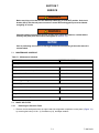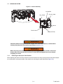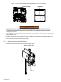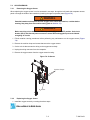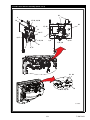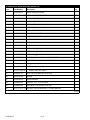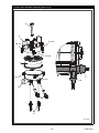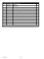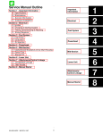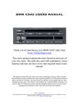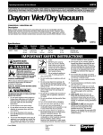
1
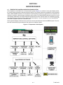
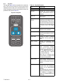
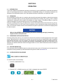
Container Refrigeration OPERATIONS, SERVICE, AND PARTS MANUAL For XtendFRESHTM Controlled Atmosphere Option T-366 Rev B OPERATIONS, SERVICE, AND PARTS MANUAL For TM XtendFRESH Controlled Atmosphere Option © Carrier Corporation, 2015 Printed in U. S. A. August 2015 TABLE OF CONTENTS PARAGRAPH NUMBER Page SAFETY SUMMARY . . . . . . . . . . . . . . . . . . . . . . . . . . . . . . . . . . . . . . . . . . . . . . . . . . . . . . . . . . . . . . . . . . . 1.1 GENERAL SAFETY NOTICES . . . . . . . . . . . . . . . . . . . . . . . . . . . . . . . . . . . . . . . . . . . . . . . . . . 1.2 FIRST AID . . . . . . . . . . . . . . . . . . . . . . . . . . . . . . . . . . . . . . . . . . . . . . . . . . . . . . . . . . . . . . . . . . 1.3 OPERATING PRECAUTIONS . . . . . . . . . . . . . . . . . . . . . . . . . . . . . . . . . . . . . . . . . . . . . . . . . . . 1.4 MAINTENANCE PRECAUTIONS . . . . . . . . . . . . . . . . . . . . . . . . . . . . . . . . . . . . . . . . . . . . . . . . 1.5 SPECIFIC DANGER, WARNING AND CAUTION STATEMENTS . . . . . . . . . . . . . . . . . . . . . . . 1–1 1–1 1–1 1–1 1–1 1–1 INTRODUCTION . . . . . . . . . . . . . . . . . . . . . . . . . . . . . . . . . . . . . . . . . . . . . . . . . . . . . . . . . . . . . . . . . . . . . . 2.1 INTRODUCTION . . . . . . . . . . . . . . . . . . . . . . . . . . . . . . . . . . . . . . . . . . . . . . . . . . . . . . . . . . . . . 2–1 2–1 DESCRIPTION . . . . . . . . . . . . . . . . . . . . . . . . . . . . . . . . . . . . . . . . . . . . . . . . . . . . . . . . . . . . . . . . . . . . . . . . 3.1 GENERAL DESCRIPTION . . . . . . . . . . . . . . . . . . . . . . . . . . . . . . . . . . . . . . . . . . . . . . . . . . . . . . 3.1.1 Refrigeration Unit − Front Section . . . . . . . . . . . . . . . . . . . . . . . . . . . . . . . . . . . . . . . . . . . . 3.1.2 Evaporator Section . . . . . . . . . . . . . . . . . . . . . . . . . . . . . . . . . . . . . . . . . . . . . . . . . . . . . . . 3–1 3–1 3–1 3–1 MICROPROCESSOR . . . . . . . . . . . . . . . . . . . . . . . . . . . . . . . . . . . . . . . . . . . . . . . . . . . . . . . . . . . . . . . . . . . 4.1 TEMPERATURE CONTROL MICROPROCESSOR SYSTEM . . . . . . . . . . . . . . . . . . . . . . . . . . 4.1.1 Key Pad . . . . . . . . . . . . . . . . . . . . . . . . . . . . . . . . . . . . . . . . . . . . . . . . . . . . . . . . . . . . . . . . 4.1.2 Display Module . . . . . . . . . . . . . . . . . . . . . . . . . . . . . . . . . . . . . . . . . . . . . . . . . . . . . . . . . . 4.1.3 Controller . . . . . . . . . . . . . . . . . . . . . . . . . . . . . . . . . . . . . . . . . . . . . . . . . . . . . . . . . . . . . . . 4.2 CONTROLLER SOFTWARE . . . . . . . . . . . . . . . . . . . . . . . . . . . . . . . . . . . . . . . . . . . . . . . . . . . . 4.2.1 Configuration Variables . . . . . . . . . . . . . . . . . . . . . . . . . . . . . . . . . . . . . . . . . . . . . . . . . . . . 4.2.2 Operational Software . . . . . . . . . . . . . . . . . . . . . . . . . . . . . . . . . . . . . . . . . . . . . . . . . . . . . . 4–1 4–1 4–2 4–3 4–3 4–3 4–3 4–3 4.2.3 Operational Software (Function Codes) . . . . . . . . . . . . . . . . . . . . . . . . . . . . . . . . . . . . . . . . MODES OF OPERATION . . . . . . . . . . . . . . . . . . . . . . . . . . . . . . . . . . . . . . . . . . . . . . . . . . . . . . UNIT PRE-TRIP DIAGNOSTICS . . . . . . . . . . . . . . . . . . . . . . . . . . . . . . . . . . . . . . . . . . . . . . . . . O2/CO2 SENSOR CALIBRATION . . . . . . . . . . . . . . . . . . . . . . . . . . . . . . . . . . . . . . . . . . . . . . . . 4–3 4–3 4–4 4–4 OPERATION . . . . . . . . . . . . . . . . . . . . . . . . . . . . . . . . . . . . . . . . . . . . . . . . . . . . . . . . . . . . . . . . . . . . . . . . . 5.1 INTRODUCTION . . . . . . . . . . . . . . . . . . . . . . . . . . . . . . . . . . . . . . . . . . . . . . . . . . . . . . . . . . . . . 5.2 OPERATION . . . . . . . . . . . . . . . . . . . . . . . . . . . . . . . . . . . . . . . . . . . . . . . . . . . . . . . . . . . . . . . . 5.3 XTENDFRESH OPTION INITIALIZATION . . . . . . . . . . . . . . . . . . . . . . . . . . . . . . . . . . . . . . . . . . 5.4 PRE-TRIP INSPECTION . . . . . . . . . . . . . . . . . . . . . . . . . . . . . . . . . . . . . . . . . . . . . . . . . . . . . . . 5.5 SYSTEM START-UP PROCEDURE . . . . . . . . . . . . . . . . . . . . . . . . . . . . . . . . . . . . . . . . . . . . . . 5.6 XTENDFRESH OPERATION . . . . . . . . . . . . . . . . . . . . . . . . . . . . . . . . . . . . . . . . . . . . . . . . . . . . 5.6.1 Modes of Operation . . . . . . . . . . . . . . . . . . . . . . . . . . . . . . . . . . . . . . . . . . . . . . . . . . . . . . . 5.7 CONTAINER VENTING PROCEDURE . . . . . . . . . . . . . . . . . . . . . . . . . . . . . . . . . . . . . . . . . . . . 5–1 5–1 5–1 5–1 5–1 5–1 5–2 5–2 5–3 TROUBLESHOOTING . . . . . . . . . . . . . . . . . . . . . . . . . . . . . . . . . . . . . . . . . . . . . . . . . . . . . . . . . . . . . . . . . . 6.1 ALARMS . . . . . . . . . . . . . . . . . . . . . . . . . . . . . . . . . . . . . . . . . . . . . . . . . . . . . . . . . . . . . . . . . . . . 6.2 XTENDFRESH ASSEMBLY NOT OPERATING . . . . . . . . . . . . . . . . . . . . . . . . . . . . . . . . . . . . . 6.2.1 Solenoid Valves Not Opening Air Vent(s) . . . . . . . . . . . . . . . . . . . . . . . . . . . . . . . . . . . . . . 6.2.2 XtendFRESH Fan(s)/XtendFRESH Scrubber Not Operating . . . . . . . . . . . . . . . . . . . . . . . 6.2.3 Heater(s) Not Operating . . . . . . . . . . . . . . . . . . . . . . . . . . . . . . . . . . . . . . . . . . . . . . . . . . . . 6–1 6–1 6–3 6–3 6–4 6–5 SERVICE . . . . . . . . . . . . . . . . . . . . . . . . . . . . . . . . . . . . . . . . . . . . . . . . . . . . . . . . . . . . . . . . . . . . . . . . . . . . 7.1 MAINTENANCE SCHEDULE . . . . . . . . . . . . . . . . . . . . . . . . . . . . . . . . . . . . . . . . . . . . . . . . . . . . 7.2 PANEL AIR FILTER . . . . . . . . . . . . . . . . . . . . . . . . . . . . . . . . . . . . . . . . . . . . . . . . . . . . . . . . . . . 7.2.1 Removing the Panel Air Filters . . . . . . . . . . . . . . . . . . . . . . . . . . . . . . . . . . . . . . . . . . . . . . 7.2.2 Replacing the Panel Air Filters . . . . . . . . . . . . . . . . . . . . . . . . . . . . . . . . . . . . . . . . . . . . . . . 7–1 7–1 7–1 7–1 7–2 4.3 4.4 4.5 i T-366 Rev B 7.3 SENSOR AIR FILTER . . . . . . . . . . . . . . . . . . . . . . . . . . . . . . . . . . . . . . . . . . . . . . . . . . . . . . . . . . 7.3.1 Removing the Sensor Air Filter Element . . . . . . . . . . . . . . . . . . . . . . . . . . . . . . . . . . . . . . . . 7.3.2 Replacing the Sensor Air Filter Element . . . . . . . . . . . . . . . . . . . . . . . . . . . . . . . . . . . . . . . . 7.4 OXYGEN SENSOR . . . . . . . . . . . . . . . . . . . . . . . . . . . . . . . . . . . . . . . . . . . . . . . . . . . . . . . . . . . . 7.4.1 Removing the Oxygen Sensor . . . . . . . . . . . . . . . . . . . . . . . . . . . . . . . . . . . . . . . . . . . . . . . 7.4.2 Replacing the Oxygen Sensor . . . . . . . . . . . . . . . . . . . . . . . . . . . . . . . . . . . . . . . . . . . . . . . 7.5 CARBON DIOXIDE SENSOR . . . . . . . . . . . . . . . . . . . . . . . . . . . . . . . . . . . . . . . . . . . . . . . . . . . . 7.5.1 Removing the CO2 Sensor . . . . . . . . . . . . . . . . . . . . . . . . . . . . . . . . . . . . . . . . . . . . . . . . . . 7.6 XTENDFRESH ACCESS PANEL . . . . . . . . . . . . . . . . . . . . . . . . . . . . . . . . . . . . . . . . . . . . . . . . . 7.6.1 Removing the XtendFRESH Access Panel . . . . . . . . . . . . . . . . . . . . . . . . . . . . . . . . . . . . . 7.6.2 Re-installing the XtendFRESH Access Panel . . . . . . . . . . . . . . . . . . . . . . . . . . . . . . . . . . . . 7.6.3 Replacing the XtendFRESH Fans . . . . . . . . . . . . . . . . . . . . . . . . . . . . . . . . . . . . . . . . . . . . 7.7 SCRUBBER FILTER . . . . . . . . . . . . . . . . . . . . . . . . . . . . . . . . . . . . . . . . . . . . . . . . . . . . . . . . . . . 7.7.1 Removing the Scrubber Filter . . . . . . . . . . . . . . . . . . . . . . . . . . . . . . . . . . . . . . . . . . . . . . . . 7.7.2 Installing the Scrubber . . . . . . . . . . . . . . . . . . . . . . . . . . . . . . . . . . . . . . . . . . . . . . . . . . . . 7.7.3 Replacing the Scrubber Motor . . . . . . . . . . . . . . . . . . . . . . . . . . . . . . . . . . . . . . . . . . . . . . 7.8 FRESH AIR SOLENOID . . . . . . . . . . . . . . . . . . . . . . . . . . . . . . . . . . . . . . . . . . . . . . . . . . . . . . . 7.8.1 Replacing the Fresh Air Solenoid . . . . . . . . . . . . . . . . . . . . . . . . . . . . . . . . . . . . . . . . . . . . 7.9 VENT POSITION SENSOR . . . . . . . . . . . . . . . . . . . . . . . . . . . . . . . . . . . . . . . . . . . . . . . . . . . . 7.9.1 Checking the VPS Switch . . . . . . . . . . . . . . . . . . . . . . . . . . . . . . . . . . . . . . . . . . . . . . . . . . 7.10 PRE-TRIP . . . . . . . . . . . . . . . . . . . . . . . . . . . . . . . . . . . . . . . . . . . . . . . . . . . . . . . . . . . . . . . . . . 7.11 CONTAINER PREPARATION . . . . . . . . . . . . . . . . . . . . . . . . . . . . . . . . . . . . . . . . . . . . . . . . . . 7.11.1 Box Checkout/Leak Test . . . . . . . . . . . . . . . . . . . . . . . . . . . . . . . . . . . . . . . . . . . . . . . . . . . 7.12 CONTAINER CURTAIN . . . . . . . . . . . . . . . . . . . . . . . . . . . . . . . . . . . . . . . . . . . . . . . . . . . . . . . 7.12.1 Installing the Curtain . . . . . . . . . . . . . . . . . . . . . . . . . . . . . . . . . . . . . . . . . . . . . . . . . . . . . . 7–3 7–3 7–4 7–5 7–5 7–5 7–6 7–6 7–6 7–7 7–7 7–7 7–7 7–7 7–10 7–11 7–12 7–12 7–12 7–12 7–12 7–14 7–14 7–16 7–16 ELECTRICAL WIRING SCHEMATIC AND DIAGRAMS . . . . . . . . . . . . . . . . . . . . . . . . . . . . . . . . . . . . . . . . 8–1 8.1 INTRODUCTION . . . . . . . . . . . . . . . . . . . . . . . . . . . . . . . . . . . . . . . . . . . . . . . . . . . . . . . . . . . . . . 8–1 SERVICE PARTS LIST . . . . . . . . . . . . . . . . . . . . . . . . . . . . . . . . . . . . . . . . . . . . . . . . . . . . . . . . . . . . . . . . . . 9.1 ORDERING INSTRUCTIONS . . . . . . . . . . . . . . . . . . . . . . . . . . . . . . . . . . . . . . . . . . . . . . . . . . . . 9.2 LETTER DESIGNATIONS . . . . . . . . . . . . . . . . . . . . . . . . . . . . . . . . . . . . . . . . . . . . . . . . . . . . . . 10 PARTS LIST FOR XTENDFRESH . . . . . . . . . . . . . . . . . . . . . . . . . . . . . . . . . . . . . . . . . . . . . . . 11 PARTS LIST FOR PANEL ASSEMBLIES . . . . . . . . . . . . . . . . . . . . . . . . . . . . . . . . . . . . . . . . . . 12 PARTS LIST FOR SENSOR ASSEMBLY . . . . . . . . . . . . . . . . . . . . . . . . . . . . . . . . . . . . . . . . . . 13 PARTS LIST FOR SCRUBBER ASSEMBLY . . . . . . . . . . . . . . . . . . . . . . . . . . . . . . . . . . . . . . . 15 PARTS LIST FOR MOTOR ASSEMBLY . . . . . . . . . . . . . . . . . . . . . . . . . . . . . . . . . . . . . . . . . . 16 PARTS LIST FOR CONTROL BOX . . . . . . . . . . . . . . . . . . . . . . . . . . . . . . . . . . . . . . . . . . . . . . INDEX .......................................................................... T-366 Rev B ii 9–1 9–1 9–1 10–1 11–1 12–1 13–1 15–1 16–1 INDEX–1 LIST OF ILLUSTRATIONS FIGURE NUMBER Page Figure 3.1 Refrigeration Unit − Front ....................................................... Figure 3.2 Evaporator Section Components 3–1 ................................................. 3–2 .................................................... 4–1 Figure 4.2 Key Pad . . . . . . . . . . . . . . . . . . . . . . . . . . . . . . . . . . . . . . . . . . . . . . . . . . . . . . . . . . . . . . . . . . . . . 4–2 Figure 4.3 Display Module ............................................................... 4–3 Figure 7.1 XtendFRESH Panel . . . . . . . . . . . . . . . . . . . . . . . . . . . . . . . . . . . . . . . . . . . . . . . . . . . . . . . . . . . . 7–2 Figure 7.2 Panel Air Filters . . . . . . . . . . . . . . . . . . . . . . . . . . . . . . . . . . . . . . . . . . . . . . . . . . . . . . . . . . . . . . . 7–2 Figure 7.3 CO2/O2 Assembly . . . . . . . . . . . . . . . . . . . . . . . . . . . . . . . . . . . . . . . . . . . . . . . . . . . . . . . . . . . . . 7–3 Figure 7.4 LEFT ACCESS PANEL AND BACK PANEL (Inside of Container) ........................ 7–4 Figure 7.5 Filter Cup . . . . . . . . . . . . . . . . . . . . . . . . . . . . . . . . . . . . . . . . . . . . . . . . . . . . . . . . . . . . . . . . . . . . 7–4 Figure 7.6 O2 Sensor ................................................................... 7–5 Figure 7.7 CO2 Sensor . . . . . . . . . . . . . . . . . . . . . . . . . . . . . . . . . . . . . . . . . . . . . . . . . . . . . . . . . . . . . . . . . . 7–6 Figure 7.8 Blower Fan 1/4 Nut Locations .................................................... 7–7 ....................................................... 7–8 Figure 4.1 Temperature Control System Figure 7.9 Hose/Scrubber Locations Figure 7.10 Removing the Scrubber Housing ................................................ 7–8 Figure 7.11 Scrubber Bolt/Spring Assemblies ................................................ 7–9 .................................................. 7–9 Figure 7.12 Scrubber Separated with Filter Figure 7.13 Carbon Filter with Gasket and Seal Plate ......................................... 7–10 ............................................... 7–10 ........................................................... 7–11 Figure 7.16 Scrubber Mounting Plate . . . . . . . . . . . . . . . . . . . . . . . . . . . . . . . . . . . . . . . . . . . . . . . . . . . . . . 7–11 Figure 7.17 Motor and Mounting Plate ..................................................... 7–12 .............................................................. 7–13 Figure 7.19 Container Leakage Test Ports . . . . . . . . . . . . . . . . . . . . . . . . . . . . . . . . . . . . . . . . . . . . . . . . . . 7–14 Figure 7.20 Magnehelic Gauge 7–15 Figure 7.14 Bolt/Spring Assembly Dimension Figure 7.15 Scrubber Housing Figure 7.18 Warning Label .......................................................... Figure 7.21 Fresh Air Panel Collars ....................................................... 7–15 Figure 8.1 62-11756-ART1-S1-RA . . . . . . . . . . . . . . . . . . . . . . . . . . . . . . . . . . . . . . . . . . . . . . . . . . . . . . . . . 8–2 Figure 8.2 62-11756-ART2S2-RA ......................................................... 8–3 Figure 8.3 62-11756-ART3-S3-RE . . . . . . . . . . . . . . . . . . . . . . . . . . . . . . . . . . . . . . . . . . . . . . . . . . . . . . . . . 8–4 Figure 8.4 62-11776-ART1-S1-RA . . . . . . . . . . . . . . . . . . . . . . . . . . . . . . . . . . . . . . . . . . . . . . . . . . . . . . . . . 8–5 Figure 8.5 62-11776-ART2-S2-RA . . . . . . . . . . . . . . . . . . . . . . . . . . . . . . . . . . . . . . . . . . . . . . . . . . . . . . . . . 8–6 Figure 8.6 62-11776-ART3-S3-RC . . . . . . . . . . . . . . . . . . . . . . . . . . . . . . . . . . . . . . . . . . . . . . . . . . . . . . . . . 8–7 iii T-366 Rev B LIST OF TABLES TABLE NUMBER Table 4–1 Key Pad Function Page ............................................................. Table 7–1 Maintenance Schedule ......................................................... v 4–2 7–1 T-366 Rev B SECTION 1 SAFETY SUMMARY 1.1 GENERAL SAFETY NOTICES The following general safety notices supplement specific warnings and cautions appearing elsewhere in this manual. These recommended precautions must be understood and applied during operation and maintenance of the equipment covered herein. The general safety notices are presented in the following three sections labeled: First Aid, Operating Precautions and Maintenance Precautions. A listing of specific warnings and cautions appearing elsewhere in the manual follows the general safety notices. Additional notices for Worker Safety, and High Voltage Safety are also included. 1.2 FIRST AID An injury, no matter how slight, should never go unattended. Always obtain first aid or medical attention immediately. 1.3 OPERATING PRECAUTIONS Always wear safety glasses. Keep hands, clothing and tools clear of the evaporator and condenser fans. Wear appropriate personal protective equipment for the work being undertaken. No work should be performed on the unit until all circuit breakers and start-stop switches are turned OFF, and power supply is disconnected. In case of severe vibration or unusual noise, stop the unit and investigate. 1.4 MAINTENANCE PRECAUTIONS Be sure power is turned OFF before installation of XtendFRESHTM Controlled Atmosphere option. Tag circuit breaker and power supply to prevent accidental energizing of circuit. Do not bypass any electrical safety devices, e.g. bridging an overload, or using any sort of jumper wires. Problems with the system should be diagnosed, any necessary repairs performed by qualified service personnel. When performing any arc welding on the container unit or refrigerated compartment, disconnect all wire harness connectors from the modules in the control box. Do not remove wire harness from the modules unless you are grounded to the container unit frame with a static safe wrist strap. 1.5 SPECIFIC DANGER, WARNING AND CAUTION STATEMENTS To help identify the hazards presented on the container unit labels and explain the level of awareness each one carries, an explanation is given with the appropriate consequences: DANGER - means an immediate hazard that WILL result in severe personal injury or death. WARNING - means to warn against hazards or unsafe conditions that COULD result in severe personal injury or death. CAUTION - means to warn against potential hazard or unsafe practice that could result in minor personal injury, product or property damage. The following safety statements are applicable to the XtendFRESH option unit used with any container unit and appear elsewhere in this manual. These recommended precautions must be understood and applied during operation and maintenance of the equipment covered herein. ! WARNING In case of electrical fire, open circuit switch and extinguish with CO2 (never use water). 1–1 T-366 Rev B ! WARNING Potential hazardous atmosphere and low oxygen levels inside the container, ventilate before entering. Stay away from doors while venting (Refer to Section 5.7). ! WARNING Before servicing unit, make sure the start-stop switch (ST) is in the OFF position. Unit circuit breaker (CB-1) and external power sources are turned OFF and tagged to prevent accidental energizing of circuits. ! CAUTION DO NOT RUN THE CAL SELECTION UNDER LOADED CONDITIONS T-366 Rev B 1–2 SECTION 2 INTRODUCTION 2.1 INTRODUCTION This Technical Supplement contains information specific to the Carrier Transicold XtendFRESHTM Controlled Atmosphere option. This supplement is to be used in conjunction with the separately bound Operation and Service Manual and Service Parts List for your particular model. Carrier Transicold’s exclusive XtendFRESH option is a modular system. The system’s ability to control the container atmosphere is done with the use of a CO2 and Ethylene scrubber. This, in turn, results in an increase in shelf life and enables longer cargo routes for certain high respiring, perishable commodities. 2–1 T-366 Rev A SECTION 3 DESCRIPTION 3.1 3.1.1 GENERAL DESCRIPTION Refrigeration Unit − Front Section The unit is designed so that the majority of the components are accessible from the front, (Figure 3.1). A manually operated venting system is located in the upper left access panel. Behind the left access panel are located CO2 and O2 sensors. The right access panel contains integrated components of the XtendFRESHTM Controlled Atmosphere option. This panel may be removed to allow entry into the evaporator section where the CO2 scrubber and other components are located. Figure 3.1 Refrigeration Unit − Front Manual Fresh Air Panel XtendFRESH Panel WARNI NG ATMOSFERA PELIGROSA VENTILE EL CONTENEDOR EN EL INTERIOR. ANTES DE ENTRAR. 䜘Ȁড 䲪ǿオ≇ ޕȠࡽȀ Ǘȟ ȻɻɎɒ ȧᨋ≇ǰ ȝ XtendFRESH Control Box 3.1.2 Evaporator Section Components of the XtendFRESH option are mounted in the evaporator section in addition to the standard refrigeration unit components. These components include (Figure 3.2) the XtendFRESH Scrubber Assembly, Motor Assembly, Manual Fresh Air Panel and Sensor Package. Air from within the container is passed through the filter to the O2 and CO2 sensors. Data is then supplied to the controller. The controller calculates O2 and CO2 values in order to maintain the preset values. 3–1 T-366 Rev B Figure 3.2 Evaporator Section Components 1 2 11 8 6 5 9 10 7 11 3 1. 2. 3. 4. 5. 6. T-366 Rev B Scrubber Filter Assembly Desorb Out Hose CO2 Scrubber Motor O2 Sensor Fresh Air Solenoid CO2 Sensor 7. 8. 9. 10. 11. ----- 3–2 Sensor Air Filter O2 Amplifier Desorb In Hose O2/CO2 Inlet O2/CO2 Outlet 4 SECTION 4 MICROPROCESSOR 4.1 TEMPERATURE CONTROL MICROPROCESSOR SYSTEM The temperature control Micro-Link 3 microprocessor system (Figure 4.1) consists of a key pad, display module, the control module (controller) and interconnecting wiring. The controller houses the temperature control software and the DataCORDER software. The temperature control software functions to operate the unit components as required to provide the desired cargo temperature and humidity. The DataCORDER software functions to record unit operating parameters and cargo temperature parameters for future retrieval. Refer to the Operation and Service manual for your particular unit for overall control descriptions. Control descriptions for the XtendFRESHTM Controlled Atmosphere option are contained herein. The key pad and display module serve to provide user access and readouts for the XtendFRESH option. The functions are accessed by key pad selections and viewed on the display module. Figure 4.1 Temperature Control System 4–1 T-366 Rev B 4.1.1 Key Pad Table 4–1 Key Pad Function The key pad (Figure 4.2) is mounted on the control box door. The key pad consists of eleven push button switches that act as the user’s interface with the controller. Descriptions of the key pad switch functions are provided in this section Table 4–1. KEY FUNCTION Code Select Accesses function codes. Pre-Trip Displays the Pre-trip selection menu. Discontinues Pre-trip in progress. Alarm List Displays alarm list and clears the alarm queue. Figure 4.2 Key Pad CODE SELECT ALARM LIST PRE TRIP Manual Defrost / Displays selected defrost mode. Interval Depressing and holding the Defrost Interval key for five (5) seconds will initiate defrost using the same logic as if the optional manual defrost switch was toggled on. MANUAL DEFROST/ INTERVAL ENTER RETURN SUPPLY C F BATTERY POWER ALT MODE Enter Confirms a selection or saves a selection to the controller. Arrow Up Change or scroll a selection upward. Pre-trip advance or test interruption. Arrow Down Change or scroll a selection downward. Pre-trip repeat backward. Return / Supply Displays non-controlling probe temperature (momentary display) Celsius / Fahren- Displays alternate English/Metric heit scale (momentary display). When set to F, pressure is displayed in psig and vacuum in “/ hg.” “P” appears after the value to indicate psig and “i” appears for inches of mercury. When set to C, pressure readings are in bars. “b” appears after the value to indicate bars. T-366 Rev B 4–2 Battery Power Initiate battery backup mode to allow set point & function code selection if AC power is not connected. ALT. Mode This key is pressed to switch the functions from the temperature software to the DataCORDER Software. The remaining keys function the same as described above except the readings or changes are made to the DataCORDER programming. 4.1.2 Display Module The display module (Figure 4.3) consists of two five digit displays and seven indicator lights. Figure 4.3 Display Module COOL HEAT DEFROST IN RANGE ALARM SETPOINT/Code 4.1.3 SUPPLY RETURN AIR TEMPERATURE/Data Controller The Micro-Link 3 controller is a dual module microprocessor. It is fitted with test points, harness connectors and a software card programming port. 4.2 CONTROLLER SOFTWARE The controller software is a custom designed program that is subdivided into configuration software and operational software. 4.2.1 Configuration Variables The unit configuration is a listing of the components and options that are installed in the unit and available for use by the operational software. The configuration variables for XtendFRESH option (FrESh) are Cnf 70 and 71. NOTICE If the present controller software does not contain XtendFRESH option compatible software version 5x62 the controller must be updated with the correct model number (e.g. 69NT40--551-114) using the PCMCIA programming card. For the XtendFRESH option, configuration Cnf70 must be set to “in”. The selection options are “Out” and “In”. Cnf71 is used to set the operating mode of XtendFRESH mode after Pre−Trip and Trip Start operations. The selection options are “OFF” and “ON”. If set to “ON”, XtendFRESH mode will be automatically activated after a Pre−Trip or Trip Start operation. 4.2.2 Operational Software The operational software is the actual operation programming of the controller which activates or deactivates components in accordance with current unit operating conditions and operator selected modes of operation. 4.2.3 Operational Software (Function Codes) The function codes are specific parameters for operation or a visible display of component conditions. The function codes for the XtendFRESH option are: Code 43 (Cd 43) which is used to select the mode of operation and the associated parameters, options available are OFF, FrESh, and TEST. For instructions on setting the parameters (refer to Section 5.1.) Code 44 (Cd 44) displays the XtendFRESH values for the CO2 and O2 sensor. 4.3 MODES OF OPERATION The operation for the refrigeration system is unchanged by the XtendFRESH option. The XtendFRESH option is a separate independent system that is controlled by the microprocessor. (refer to Section 5.2 ) 4–3 T-366 Rev B 4.4 UNIT PRE-TRIP DIAGNOSTICS Pre-Trip Diagnostics is an independent controller function that suspends normal refrigeration controller activities and provides preprogrammed test routines. The test routines include Auto Mode testing, which automatically performs a pre programmed sequence of tests, or Manual Mode testing, which allows the operator to select and run any of the individual tests. (refer to Section 7.10). 4.5 O2/CO2 SENSOR CALIBRATION Sensor calibration is performed by activating calibration mode, which is an option under Cd43 test mode. The O2 and CO2 calibrations should be performed with only fresh air (refer to Section 5.6.1). T-366 Rev B 4–4 SECTION 5 OPERATION 5.1 INTRODUCTION This section addresses the additional operating requirements for the XtendFRESHTM Controlled Atmosphere option. No operating parameters are changed except for XtendFRESH settings. For information pertaining to the operation of the refrigeration system, refer to the Operation and Service Manual for your particular model. 5.2 OPERATION The XtendFRESH (FrESh) option is a modular option that offers enhanced functionality to help slow the ripening process of perishable cargo by removing ethylene and simultaneously controlling CO2 and O2 levels in multiple combinations, enabling the fresh transport of perishables on longer voyages. The system’s ability to control the container atmosphere is performed with the use of a CO2 and ethylene scrubber. During the scrubbing process CO2 and ethylene are removed. The scrubber allows for the control of CO2.The oxygen is controlled by the use of the cargo’s natural respiration and by opening and closing solenoid operated air vents. An O2 Sensor monitors the level of O2 and allows the system to prevent the O2 levels from dropping below the lower set point. NOTICE While the XtendFRESH option is operating, the process of inducing ripening by introducing ethylene should not be performed. 5.3 XTENDFRESH OPTION INITIALIZATION Following a delay after power up, the controller will check for the presence of a carbon dioxide sensor and oxygen sensor. When detection is confirmed, the controller will resume the previous XtendFRESH mode of operation before power interruption. If one of the sensors is not detected, the only modes of operation available will be Test, and OFF. If the unit prior to power interruption was operating in XtendFRESH mode and one of the sensors is not detected, the controller will activate either AL09 Oxygen sensor or AL10 Carbon Dioxide sensor alarm condition to alert the user. 5.4 PRE-TRIP INSPECTION Pre−trip testing of the XtendFRESH option is performed via function code 43. During the pre−trip inspection the technician will verify operation by visual observation during this test. Refer to Section 7.10 5.5 SYSTEM START-UP PROCEDURE To start the system, do the following: 1. Press the “CODE SELECT” key. CODE SELECT 2. Press the “UP” or “DOWN“ arrow key until “Cd43“ is displayed, then press “ENTER”. ENTER or until then 5–1 T-366 Rev B 3. Press the “UP” or “DOWN” arrow key to access the “FrESh” mode. When the desired mode of operation is displayed, press the enter key to access the sub menu parameters. ENTER or 5.6 until then XTENDFRESH OPERATION The modes of operation are: FrESh, OFF, and tESt. Within each of these modes of operation are sub menus that have selectable parameters. Not all parameters are available in each sub menu. When setting any mode of operation, the entire process must be followed to ensure all parameters are set. 5.6.1 Modes of Operation 1. In this mode features can be activated and control parameters can be set. With “FrESh” shown in the right display window, pressing “ENTER” will activate a submenu. From the submenu user can set values for the oxygen Setpoint and carbon dioxide setpoint values. Operational Parameters CO2 Set Point (CO2SP) − is the maximum level of carbon dioxide that is allowed for the cargo. The range is from 0% to 19% in 1% increments; the default setting is 5%. O2 Set Point (O2SP) − is the minimum level of oxygen that is allowed for the cargo. The range is from 3% to 21% in 1% increments; the default setting is 10% 2. A setting of “OFF” will disable all XtendFRESH operations. The XtendFRESH vents will be closed and the scrubber will remain off. This will be the default mode anytime a frozen mode of operation has been selected. Whenever a frozen setpoint is selected, the current XtendFRESH setting will be saved. 3. “tESt” mode allows the operator to test system operation of the mechanical components and the calibration of the sensors. Upon entering test mode there are two options available (tESt and CAL). Each of the different modes is explained in detail below. Use the up or down arrows keys to select either the tESt or CAL option. a. tESt Option - On selection, a mechanical component operational test which is a visual inspection, followed by a CO2 and O2 sensor test and calibration will be completed as follows: 1. Mechanical Test: the fresh air solenoids will open for eight seconds and close followed by the blower fans and scrubber motor turning on for 60 seconds. Visual inspection of each occurrence is required. If the unit is equipped with the UVPS option, you need to manually check the operation of the UVPS switch. This switch gives priority to the XtendFRESH option, no longer displaying the UVPS setting. To ensure the switch is working, with CD43 set to FrESh, rotate the UVPS and ensure CD45 does not reflect the change. 2. Sensor Test: the controller will perform a range check of the CO2 (0% to 1.0%) and O2 (above 19%) sensors. If both meet this requirement, a calibration test “CAL StArt” will be displayed for five seconds and a calibration of each sensor will be performed. If both sensors pass calibration, a “CAL PASS” will display for five minutes or until the user presses and holds the Code Select key for three seconds. In either case, normal operation will be resumed. T-366 Rev B 5–2 If one or both of the sensors are outside of the range check condition above, the failed results will be displayed (i.e. “CO2 OUt”, “O2 In….), alternating every five seconds. To exit, the user should press and hold the Code Select key for three seconds. If the range check fails (indicating a drifted sensor), ensure box is clean of cargo remnants from last trip, open back doors, and rerun test. If the range check fails a second time, replace the sensor that is out of range. Both sensors will be calibrated based on the conditions in the container. If either of the sensors fail open or shorted, an Alarm 09 for O2 sensor or Alarm 10 for CO2 sensor will occur. b. CAL Option - When entering CAL press ENTER the sensor tests are performed. The controller will perform a range check of the CO2 (0% to 1.0%) and O2 (above 19%) sensors. If both meet this requirement, a calibration test “CAL StArt” will be displayed for five seconds and a calibration of each sensor will be performed. If both sensors pass calibration, a “CAL PASS” will display for five minutes or until the user presses and holds the Code Select key for three seconds. In either case, normal operation will be resumed. If one or both of the sensors are outside of the range check condition above, the failed results will be displayed (i.e. “CO2 OUt”, “O2 In….), alternating every five seconds. To exit, the user should press and hold the Code Select key for three seconds. If the range check fails (indicating a drifted sensor), ensure box is clean of cargo remnants from last trip, open back doors, and rerun test. If the range check fails a second time, replace the sensor that is out of range. Both sensors will be calibrated based on the conditions in the container. If either of the sensors fail open or shorted, an alarm 09 for O2 sensor or alarm 10 for CO2sensor will occur. NOTICE It is required that the calibration procedure only be performed during pre−trip or when the container has been fully vented. 5.7 CONTAINER VENTING PROCEDURE ! WARNING Potential hazardous atmosphere and low oxygen levels inside the container, ventilate before entering. Stay away from doors while venting. (Refer to Section 5.7) 1. Set the ST switch to the ON position. 2. Manually open the Manual Fresh Air vent. a. Avoid any direct breathing of the venting gases from the air makeup vent. 3. Go to code 43, select XtendFRESH mode and set the operating parameters to 21% O2. Refer to Section 5.6 4. Allow the refrigeration unit to run. This allows the evaporator fans to exchange low-oxygen level air with ambient air. 5. Monitor the container internal environment via code 44 (Cd44). 6. When the oxygen level reaches a safe level ~ 20 ± 2%. Open both of the container rear doors and pull back the curtain to facilitate the clearing of the hazardous atmosphere. Step away from the container rear doors. Continue refrigeration operation for five minutes prior to entry or unloading of the container. 5–3 T-366 Rev B T-366 Rev B 5–4 SECTION 6 TROUBLESHOOTING 6.1 ALARMS Alarm display is an independent controller software function. If an operating parameter is outside of the expected range or a component does not return a valid signal back to the controller, an alarm is generated. The XtendFRESHTM Controlled Atmosphere option alarms are AL07, AL09, AL10, AL29, and AL62. AL07 MANUAL FAV OPEN Cause: For units equipped with XtendFRESH and a Vent Position Sensor, the controller will monitor the manual fresh air opening at a pre-determined time. If during this time the fresh air vent is open and XtendFRESH is active an alarm will be generated. If alarm is active the controller monitors the manual fresh air once per hour. Upon clearing the alarm the controller goes back to monitoring at the pre-determined time. Vent Position Sensor (VPS) Component Troubleshooting Manually reposition vent and confirm using Cd45. Refer to Section 7.9. Corrective Action If unable to obtain zero reading, replace defective VPS. AL09 O2 SENSOR FAILURE Cause: Triggered anytime the O2 sensor reading is outside of the normal operation range, after an initial signal was detected. O2 sensor, O2 Amplifier Component Troubleshooting Check voltage at KD4 to TP9 Corrective Action Open the Manual Fresh Air Vent Corrective Action Check wiring, Section 5.6.1 Modes of Operation. AL10 CO2 SENSOR FAILURE Cause: Triggered anytime the CO2 sensor reading is outside of the normal operation range, after an initial signal was detected. Component CO2 sensor Troubleshooting Check the voltage at MC5 to TP9 Corrective Action None 6–1 T-366 Rev B AL29 LOSS OF ATMOSPHERIC CONTROL Cause: Triggered whenever the CO2 level is above its upper limit or O2 level is below its lower limit for more than 60 minutes after the unit has been in range. The alarm is triggered off when the levels return to within the normal range. Component Solenoid Air Vents. Troubleshooting Check to see if the Solenoid Valves are Opening Air Vents. Corrective Action Perform the procedure (Section 6.2.1). Component XtendFRESH Fans Troubleshooting Check to see if the XtendFRESH Fans are running Corrective Action Perform the procedure (Section 6.2.2). AL62 O2 OUT OF RANGE Cause: This is a notification alarm and does not pose a risk to fresh produce. AL62 is triggered when there is an indication that the O2 level is rising after reaching its setpoint (+ 1%). If O2 level exceeds 4% above setpoint the alarm is activated The alarm does not activate if the unit was pre-tripped or trip started between last reaching its O2 setpoint and exceeding the plus 4%, or if power has been turned off for eight hours. The alarm is deactivated if O2 drops below setpoint + 1% or if a pre-trip or trip start is performed. Component Scrubber Fuse Troubleshooting Check to see if Scrubber Fuse is blown. Corrective Action Replace Scrubber Fuse Component XtendFRESH Solenoid Valves Troubleshooting Check to see if XtendFRESH Solenoid Valves are stuck in the open position. Corrective Action Manually close XtendFRESH Solenoid Valves. T-366 Rev B 6–2 6.2 6.2.1 XTENDFRESH ASSEMBLY NOT OPERATING Solenoid Valves Not Opening Air Vent(s) Code 43 run “Test” Mode Solenoid Valves Not Opening Yes Operation Normal Vents Open No Check Fuse FX4 in XF Control Box Check wiring connections to reefer controller No Does the XF contactor energize? Yes Fuse is OK Yes Replace Solenoid(s) No Check wiring for short, replace fuse Yes Repair wiring or connections to solenoids No Wiring Connections to solenoids OK 6–3 T-366 Rev B 6.2.2 XtendFRESH Fan(s)/XtendFRESH Scrubber Not Operating XtendFRESH Fan(s) or XtendFRESH Scrubber Motor Not Operating Code 43 run “Test” Mode No Check Fuse FX6 in Reefer Control Box Check wiring for short, replace fuse Check wiring connections to reefer controller No No Fuse is OK Yes Fuse is OK Yes Repair wiring and connections T-366 Rev B No Wiring Yes Connections to Fans or Motor OK? 6–4 Yes Operation Normal Check Fuse FX3 in XF Control Box Yes Does the XS contactor energize? Visually check Fans/ Motor are turning Replace Fan(s) or Motor No Check wiring for short, replace fuse 6.2.3 Heater(s) Not Operating Heater(s) Are Not Operating Open XtendFRESH Control Box Code 43 run “Test” Mode Does XH Contactor energize? Yes Check current draw from top of XH Contactor No Check Fuses FX5 and FX6 in Reefer Control Box Is Current Draw 1 amp Yes ~ Operation Normal No Replace Fuse(s) No Fuses Are OK Yes No Repair wiring, connections Is there 460 volts to Heaters? No Check wiring to XH Contactor Check Fuses FX1 and FX2 in Reefer Control Box Wiring connections to XH Contactors OK? Fuses Are OK Yes Replace XH Contactor Yes Do both heaters have Resistance 220-270 ohms? Yes Operation Normal No Replace Heaters No Replace Fuse(s) Yes Repair wiring from Main Control Box to XHL1 and XHL2 6–5 T-366 Rev B SECTION 7 SERVICE ! WARNING Before servicing unit, make sure the start-stop switch (ST) is in the OFF position. Unit circuit breaker (CB-1) and external power sources are turned OFF and tagged to prevent accidental energizing of circuits. ! WARNING Potential hazardous atmosphere and low oxygen levels inside the container, ventilate before entering. Stay away from doors while venting (refer to Section 5.7). NOTICE Prior to performing service work, a thorough review and understanding of the entire manual is recommended. 7.1 MAINTENANCE SCHEDULE Table 7–1 Maintenance Schedule OPERATION REFERENCE SECTION Pre-Trip Pre-Trip Inspection - before starting. Section 7.10 Verify container meets leak specification. Section 7.11 Inspect air intake filters. Section 7.2 Replace poly sheet curtain. Section 7.12 Calibrate O2 and CO2 sensors. Section 5.6.1 Bi-Annually Replace sensor air filter. Section 7.3 Replace panel air filters. Section 7.2 Every 3 Years Replace scrubber cartridge. 7.2 Section 7.7.1 PANEL AIR FILTER 7.2.1 Removing the Panel Air Filters 1. Remove the louvered panels from the right−hand side refrigeration evaporator access panel, (Figure 7.1), by removing the bolts (1/4−20 x 1), flat washers (1/4), and Mylar washers. 7–1 T-366 Rev B Figure 7.1 XtendFRESH Panel Louvered Panels WARNI NG ATMOSFERA PELIGROSA VENTILE EL CONTENEDOR EN EL INTERIOR. ANTES DE ENTRAR. 䜘Ȁড䲪ǿ ޕȠࡽȀȻɻ オ≇Ǘȟ Ɏɒȧᨋ≇ǰ ȝ 2. Loosen two nuts (#10−32) that secure the brackets holding the air filter in place. 3. Slide the panel air filters out (Figure 7.2). Figure 7.2 Panel Air Filters 7.2.2 Replacing the Panel Air Filters 1. Install the panel air filter by reversing the above steps. Be sure filter is fully inserted until it hits the stop. Also be sure to install the filters in the correct air flow direction. The filter’s wire mesh must be facing towards the inside of the container. T-366 Rev B 7–2 7.3 SENSOR AIR FILTER Figure 7.3 CO2/O2 Assembly O2 Amplifier CO2 Sensor CO2/O2 Outlet O2 Sensor CO2/O2 Inlet Sensor Air Filter ----- ! WARNING Potential hazardous atmosphere and low oxygen levels inside the container, ventilate before entering. Stay away from doors while venting (refer to Section 5.7). ! WARNING Before servicing unit, make sure the start-stop switch (ST) is in the OFF position. Unit circuit breaker (CB-1) and external power sources are turned OFF and tagged to prevent accidental energizing of circuits. 7.3.1 Removing the Sensor Air Filter Element When replacing the Sensor Air Filter element it can be accessed in two ways: through the left−hand side evaporator access panel or through the inside of the container by removing the upper back panel (Figure 7.4). 7–3 T-366 Rev B Figure 7.4 LEFT ACCESS PANEL AND BACK PANEL (Inside of Container) Left Access Panel ! Back Panel WARNING Before servicing unit, make sure the start-stop switch (ST) is in the OFF position. Unit circuit breaker (CB-1) and external power sources are turned OFF and tagged to prevent accidental energizing of circuits. 1. Follow container venting procedures before performing any maintenance on the sensor air filter element (refer to Section 5.7). 2. By hand, unscrew and remove the filter cup from the bottom of the sensor air filter assembly (Figure 7.5). 3. Remove the filter element from the filter assembly. 7.3.2 Replacing the Sensor Air Filter Element 1. Install the sensor air filter element by reversing the above steps. Figure 7.5 Filter Cup Filter Cup T-366 Rev B 7–4 7.4 OXYGEN SENSOR 7.4.1 Removing the Oxygen Sensor When replacing the oxygen sensor it can be accessed in two ways: through the left−hand side evaporator access panel or through the inside of the container by lowering the upper evaporator panel (Figure 7.4). ! WARNING Potential hazardous atmosphere and low oxygen levels inside the container, ventilate before entering. Stay away from doors while venting (refer to Section 5.7). ! WARNING Before servicing unit, make sure the start-stop switch (ST) is in the OFF position. Unit circuit breaker (CB-1) and external power sources are turned OFF and tagged to prevent accidental energizing of circuits. 1. Follow container venting procedures before performing any maintenance on the oxygen sensor (Figure 7.6). 2. Remove the cushion clamp and screws that secure the oxygen sensor. 3. Cut the wire tie that secures the wiring to the oxygen sensor body. 4. Unplug the wiring connector from the receptacle. 5. Remove the oxygen sensor from the oxygen sensor housing. Figure 7.6 O2 Sensor Cushion Clamps O2 Sensor 7.4.2 Replacing the Oxygen Sensor 1. Install the oxygen sensor by reversing the above steps. 7–5 T-366 Rev B 7.5 CARBON DIOXIDE SENSOR 7.5.1 Removing the CO2 Sensor When replacing the CO2 sensor it can be accessed in two ways: through the left−hand side evaporator access panel or through the inside of the container by removing the upper back panel (refer to Figure 7.4). Refer to Figure 7.3 for the physical location of the CO2 sensor. ! WARNING Potential hazardous atmosphere and low oxygen levels inside the container, ventilate before entering. Stay away from doors while venting (refer to Section 5.7). ! WARNING Before servicing unit, make sure the start-stop switch (ST) is in the OFF position. Unit circuit breaker (CB-1) and external power sources are turned OFF and tagged to prevent accidental energizing of circuits. 1. Follow container venting procedures before performing any maintenance on the CO2 sensor. 2. Remove the electrical connector and the inlet and outlet tubes from the body of the sensor (refer to Figure 7.3). 3. Loosen the screws which holds the CO2 sensor to the fan deck bracket. 4. Install replacement CO2 sensor by reversing steps 2 and 3. 5. Calibrate the CO2 sensor, following the test procedure (Section 5.6.1). Figure 7.7 CO2 Sensor CO2 Sensor 7.6 XTENDFRESH ACCESS PANEL ! WARNING Before servicing unit, make sure the start-stop switch (ST) is in the OFF position. Unit circuit breaker (CB-1) and external power sources are turned OFF and tagged to prevent accidental energizing of circuits. T-366 Rev B 7–6 7.6.1 Removing the XtendFRESH Access Panel 1. Remove the two louvered panels from the upper right access panel (refer to Figure 7.1) by removing the mounting bolts and T.I.R locking device if used. 2. Remove the eight (8) (#10-32) nuts holding the ducts in place. Leave the blower fans (2) mounted to the ducts. Gently push the ducts away from the back of the panel (refer to Figure 7.8). Figure 7.8 Blower Fan 1/4 Nut Locations #10-32 Nuts 3. Remove the access panel mounting bolts and T.I.R. locking device if used. 4. Carefully pull the access panel out slightly to reach inside of the unit and unplug the fresh air solenoid and fan connectors. 5. Set the panel aside to make any necessary repairs. 7.6.2 Re-installing the XtendFRESH Access Panel 1. Plug in the fresh air solenoid and fan connections, on the back of the access panel. 2. Install the access panel, and secure with mounting hardware. 3. Reach into the access panel and pull the transition ducts into position of the access panel. Make sure the gasket is properly seated. 4. Secure the ducts in place with eight (8) (#10-32) nuts. Refer to Figure 7.8 5. Re-attach louver panels. 7.6.3 Replacing the XtendFRESH Fans 1. Remove the two louvered panels from the upper right access panel (refer to Figure 7.1) by removing the mounting bolts and T.I.R. locking device if used. 2. Unbolt the defective fan from the panel; unplug the blower connections. Make note of the fan direction. 3. Replace the defective fan, making sure the fan will be turning in the proper direction. The fan on the right side should have the label showing, and the left fan the label should be on the inside facing the transition. 4. Re-attach the fan wiring connections. 5. Inspect the air filters. Clean or replace as needed. 6. Install louvered panel with filters to the access panel. 7.7 7.7.1 SCRUBBER FILTER Removing the Scrubber Filter When replacing the Scrubber it can be accessed through the inside of the container, refer to Figure 7.9 for the physical location of the Scrubber. 7–7 T-366 Rev B Figure 7.9 Hose/Scrubber Locations Desorb In Desorb Out Scrubber Filter Assembly 1. Start by lowering the back panel (refer to Figure 7.4). 2. Unplug the scrubber heaters and thermostat wiring. 3. Loosen the hose clamps and remove the hose from the scrubber filter assembly, top and bottom (refer to Figure 7.9). 4. Remove the two (2) bolts securing the scrubber housing to the top mounting bracket. Turn the scrubber housing 10 degrees to remove it from the unit (refer to Figure 7.10). Figure 7.10 Removing the Scrubber Housing Remove Mounting Bolts (2) Turn Housing to remove 5. Move the scrubber housing to a clean area for disassembly. 6. Remove the four (4) bolt and spring assemblies holding the scrubber housing together (refer to Figure 7.11). T-366 Rev B 7–8 Figure 7.11 Scrubber Bolt/Spring Assemblies Bolt and Spring Assembly (4) 7. Separate the upper and lower halves of the scrubber housing. 8. Remove the carbon filter for the scrubber housing along with the gaskets and aluminum seal plate (Refer to Figure 7.12). Figure 7.12 Scrubber Separated with Filter Carbon Filter with Gaskets and Aluminum Seal Plate 9. Install the new seal plates, gaskets, and filter into the bottom housing, making sure the gasket and seal plate are in the proper position. The side of the seal plate with the X must be installed towards the gasket. (Refer to Figure 7.13). 7–9 T-366 Rev B Figure 7.13 Carbon Filter with Gasket and Seal Plate Gasket Seal Plate Carbon Filter 10.Place the top plate and gasket on the top of the filter. Align the top housing so that the gasket and aluminum plate fit into the recess in the housing. 11. Bolt the housing together with the bolt and spring assemblies (4), (refer to Figure 7.11). 12.When tightening the spring assemblies the spring gap must be 0.310 inches (8mm) between the bottom of the washer and the housing tab surface (Refer to Figure 7.14). Figure 7.14 Bolt/Spring Assembly Dimension 0.310in 7.7.2 8mm Installing the Scrubber 1. Align the scrubber shaft in the slot of the coupling attached to the motor. NOTICE It will aid in the installation if the shaft coupling (on top of the shaft) is loose to help self-align. It will tighten during motor rotation. 2. The scrubber requires a ten degrees turn in order to secure the back portion into the mounting tabs (refer to Figure 7.15). T-366 Rev B 7–10 Figure 7.15 Scrubber Housing 3. Connect the hoses from the air ducts to the scrubber housing (Refer to Figure 7.9). 4. Make sure the hose is completely on the housing, tighten the hose clamps and use Ty-Raps to secure the hoses to the gusset. Be sure the hoses are level. 5. Reconnect the scrubber heaters and thermostat wiring. Use Ty-Raps to secure the wiring to prevent chafing. 7.7.3 Replacing the Scrubber Motor When replacing the Scrubber motor it can be accessed through the inside of the container, refer to Figure 7.9 for the physical location of the motor. 1. Start by removing the scrubber housing refer to Section 7.7.1 2. After removing the scrubber housing remove the four (4) 1/4-20 mounting screws that attach scrubber mounting plate to the fan deck. Refer to Section Figure 7.16 Figure 7.16 Scrubber Mounting Plate 4 Mounting Screws 3. Carefully lower the plate while unplugging the scrubber motor connection. It may be necessary to cut the wire ties. 4. Remove the four (4) hex head screws holding the motor to the mounting plate (Refer to Figure 7.17). 7–11 T-366 Rev B Figure 7.17 Motor and Mounting Plate 5. Replace the motor and follow the instructions in reverse order. 7.8 FRESH AIR SOLENOID 7.8.1 Replacing the Fresh Air Solenoid 1. Remove the right−hand evaporator panel (Section 7.6.1). 2. There are two solenoids in the panel. The one on the left, as facing the panel from the back requires the removal of a cover plate to access the four mounting screws. Remove the four (4) 10−24 mounting screws. 3. Remove the 10−24 nuts and replace the defective solenoid reversing steps 1−3. 7.9 VENT POSITION SENSOR For units equipped with XtendFRESH and a Vent Position Sensor, there is a solid state switch that while change depending on unit operation. If the unit is in XtendFRESH mode (Cd43 set to “FrESH”) the signal provided to the controller will come from the Oxygen sensor. If Cd43 set to “OFF” the signal to the controller will be from the VPS. 7.9.1 Checking the VPS Switch To check the operation of the VPS switch, go to code 43 set the option to “OFF”. Go to code 45, then open the manual fresh air panel and verify the sensor is reading in code 45. Go back to code 43 and activate XtendFRESH (“FrESH”). Code 44 should now show the CO2 and O2 values. Code 45 should display “----“. 7.10 PRE-TRIP To ensure a successful XtendFRESH trip the following pretrip steps should be performed prior to each trip. The following procedure is to be used in alignment with the 5x61 release. 1. Remove the rear upper back panel. 2. Go to Code Select Cd18 and ensure container has software version (5X61 or higher). Do this by pressing the “UP” or “DOWN“ arrow key until “Cd18“ is displayed, then press “ENTER” T-366 Rev B 7–12 3. Then go to Code Select Cd43 and arrow select “tESt” mode. Refer to Section 5.5. On entering test mode there are two selectable options available (tESt and CAL). Refer to Section 5.6. 4. Select “tESt”. On selection a mechanical component operational test which is visual inspection, followed by a CO2 and O2 sensor test and calibration will be completed as followed: a. Mechanical Test: the fresh air solenoids will open for eight seconds and close followed by the blower fans and scrubber motor tuning on for 60 seconds. Visual inspection of each occurrence is required. If the units is equipped with the UVPS option you need to manually check the operation of the UVPS / switch. This switch gives priority to the XtendFRESH option, and as such the UVPS will no longer be displayed. To ensure the switch is working, with CD43 active, rotate the UVPS and ensure the display does reflect the change. b. Sensor Test: the controller will perform a range check of the CO2 (0% to 1.0%) and O2 (above 19%). If both meet this requirement a calibration test “CAL StArt” will be displayed five seconds and a calibration of each sensor will be performed. If both sensors pass calibration, a “CAL PASS” will display for five minutes, or until the user presses and holds the Code Select key for three seconds. In either case, normal operation will be resumed. If one or both of the sensors are outside of the range check condition, the failed results will be displayed (i.e. “CO2 OUt”, “O2 In), alternating every five seconds. To exit the user presses and holds the Code Select key for three seconds. If the range check fails, ensure box is clean of cargo remnants from last trip and rerun test. If the range check fails a second time, exit the test mode and proceed to and enter the CAL selection option in the CD 43 tESt mode. Sensor will be calibrated based on the conditions in the container. If either of the sensors fails the calibration an Alarm 09 for O2 sensor or alarm 10 for CO2 sensor will occur. Alarm 09 is for the O2 sensor and alarm 10 ! CAUTION DO NOT RUN THE CAL SELECTION UNDER LOADED CONDITIONS 5. On completion of the Cd43 test, prepare box for an air leak test. 6. Check the defrost drain hose for any damage and ensure that the trap is filled with water. 7. Reinstall the upper back panel and ensure the floor drains within the container are sealed. 8. Ensure the manual fresh air panel is closed tight and that the warning label is in place on the unit. Figure 7.18 Warning Label 9. Check air tightness of box following the Box Checkout/Leak Test procedure. Refer to Section 7.11.1. Box must meet or exceed the air tightness requirement. 10.Install new curtain, load cargo and select the desired the O2 and CO2 levels via Code Select Cd43 “FrESh” modes. Refer to Section 5.5. 11. Immediately after cargo is loaded it is recommended to perform a second leak test on the box. 7–13 T-366 Rev B 7.11 CONTAINER PREPARATION Inspection. Check the rear container doors and door handles for proper operating condition. Check for proper installation of labels on the container and refrigeration unit. Always visually check the inside of the container for occupants prior to closing the doors. 7.11.1 Box Checkout/Leak Test When using the XtendFRESH system, the box must conform to leak rates in order to maintain control of the O2 and CO2 set points. The minimal box requirement is a pressure decay of 2 inch WG (50mm) to 1 inch WG (25mm) of 8 minutes or more for a 40 foot container and 4 minutes or more for a 20 foot container. It is recommended that it be checked prior to the voyage. To perform this check some units may be equipped with two pressure connection ports on the front of the unit. If the ports are not available then a Manual Fresh Air panel (part number 79-04098-00) with two Schrader ports should be installed. Figure 7.19 Container Leakage Test Ports * If ports are not available on Unit then replace Manual Fresh Air panel disc with a disc that has pressure decay ports. (PN: 79-04098-00) Port Location (Not available on all Units) One of the ports is connected to a pressurized air supply and the other is connected to a Magnehelic pressure gauge. The pressure gauge monitors the container leakage rate. Prior to performing the leak test: • seal the floor drains with plugs • ensure the unit condensate drain line is filled with water • ensure the air makeup panel is tightly closed • insert plug in drain hose; install container curtain at the rear door • seal the door shut When installing the door curtain (part number 76-50215-00), place curtain around door and seal curtain along top and sides of box and close door. Curtain should be visible throughout the perimeter of the doors. Tape may be used to assist in holding the curtain in position. The use of curtain tracks are not recommended with the XtendFRESH option and always use a new curtain as small rip in the curtain can result in a failure of the test. After connecting the gauges turn on the air supply and regulate the air pressure to 40-60 psi. When the Magnehelic gauge reads 2.5 inches of water gauge, shut off the air supply. Do not exceed 3.0 inches of WG. Monitor the Magnehelic pressure gauge for the drop in air pressure in the container. When the Magnehelic pressure gauge reads 2 inches, start a timer. When the Magnehelic pressure gauge reads 1 inch of WG, stop timing. The amount of time expired should be no less than eight minutes or more for a 40 foot container and four minutes or more for a 20 foot container. If it is less than then the required time (i.e 6 min) then the container needs to be checked for leaks. T-366 Rev B 7–14 Figure 7.20 Magnehelic Gauge Start Timer* Check Container for Leaks Shut Off Air Supply * 40’ Container - at least 8 minutes 20’ Container - at least 4 minutes To check for leaks the following actions are recommended: External checks: Re-pressurize the container to 2 inches water gauge and look for leaks at the following areas using soapy water (mixture of dish detergent and water) looking for bubbles. • Inspect evaporator unit access panels – Check gasket is properly in place, Tighten access panel bolts to 60 inch-lbs. and caulk if necessary. • Inspect at condensate drain outlet line - If leaking, complete other checks and re-inspect internally. • Inspect unit/container box joints - Caulk if necessary. • Inspect the through-wire bulkhead connections – Secure and caulk if required. • Inspect the container floor drains under container (if accessible) – If leaking, complete external checks and reinspect internally. • Inspect the rear door seals – Ensure curtain is properly installed (curtain should be visible throughout the perimeter of the doors) – Remove an install new curtain. De-pressurize the container prior to opening the container. • Ensure manual fresh air panel is equipped with collars (Part #:79-04064-00). Figure 7.21 Fresh Air Panel Collars Collars Fresh Air Panel Internal checks: Remove pressure within the container and inspect the following locations: • Inspect curtain for any rips – Replace curtain • Inspect the container floor drains - Ensure plug is secure and in place. 7–15 T-366 Rev B • Inspect condensate drain outlet line - Confirm drain line is filled with water. • Inspect for any internal wall damage – Repair and caulk as required • Inspect floor to side wall joint, floor to front bulkhead joint for any damage – Repair and caulk as required On completion of the checks and any associated repairs it is recommended that the unit be tested again to reconfirm it that it now meets the required level. 7.12 CONTAINER CURTAIN ! WARNING Potential hazardous atmosphere and low oxygen levels inside the container, ventilate before entering. Stay away from doors while venting (Refer to Section 5.7). 7.12.1 Installing the Curtain 1. Open the rear doors of the container. 2. Use a new curtain. 3. Fully unfold the door curtain package and hold it up to the container opening. Tape maybe be used to assist holding the curtain in position. 4. Place curtain around door and seal curtain along top and sides of box. The use of curtain tracks are not recommended with the XtendFRESH option. 5. Close the rear doors of the container. SECTION 8 ELECTRICAL WIRING SCHEMATIC AND DIAGRAMS 8.1 INTRODUCTION This section contains the Electrical Schematics and Wiring Diagrams for a basic unit with XtendFRESHTM Controlled Atmosphere option. Refer to the Operation and Service manual for your particular unit for actual schematic and wiring diagram information on components outside the XtendFRESH option. 8–1 T-366 Rev B Figure 8.1 62-11756-ART1-S1-RA T-366 Rev B 8–2 Figure 8.2 62-11756-ART2S2-RA 8–3 T-366 Rev B Figure 8.3 62-11756-ART3-S3-RE T-366 Rev B 8–4 Figure 8.4 62-11776-ART1-S1-RA 8–5 T-366 Rev B Figure 8.5 62-11776-ART2-S2-RA T-366 Rev B 8–6 Figure 8.6 62-11776-ART3-S3-RC 8–7 T-366 Rev B SECTION 9 SERVICE PARTS LIST 9.1 ORDERING INSTRUCTIONS All orders and inquiries for parts must include: Parts Identification Number (PID), Model Number, Unit Serial Number, Part Number, Description of part as shown on list and Quantity required. Address all correspondence for parts to the following address: CARRIER TRANSICOLD DIVISION Replacement Components Group, TR-20 P.O. Box 4805, Syracuse, New York 13221 or FAX to: (315) 432-3778 9.2 LETTER DESIGNATIONS The following letter designations are used to classify parts throughout this list: A/R= As Required N/A= Not Available NS = Not shown in illustration NSS = Not sold separately − Order next higher assembly or kit PID = Parts Identification Number − essential to identify unit configuration. PL = Purchase Locally SST = Stainless Steel − 300 Series unless otherwise specified. SV = Suffix SV − added to part number designates service replacement part. 9–1 T-366 Rev B T-366 Rev B 9–2 10 Parts List for XtendFRESH (Sheet 1 of 2) 5, 6, 8 11 1, 9, 10, 12 3, 4 14 2, 7, 9 13 3, 4 77ï01713 10–1 T-366 Rev B 10 Parts List for XtendFRESH (Sheet 2 of 2) Item Part Number Description Qty 1 79−04044−00 Scrubber Assembly, XtendFRESH 1 2 79−04028−00 Scrubber Motor Assembly 1 3 58−04994−00 XtendFRESH Hose 2 4 44−00045−05 Clamp, Hose, 2.06−3.00 Worm Type 4 5 68−17663−00 Plate, Cover, .063 Thick Aluminum 1 6 66−U−1−5321−8 Washer, Plain, #10 Type A 6 7 66−U−1−5321−7 Screw, Cap Hexhead, 1/4−20 x 1 4 8 66−U−1−5371−6 Screw, Machine Hexhead, #10−24 x .750 Slotted 6 9 66−U−1−5321−7 Washer, Plain 1/4 W Type A 12 10 66−U−1−5361−47 Bolt, Machine Hexhead, 1/4-20 x 1.25 Long 2 11 44−00361−00 Clip, Retaining, .88−1.00 Wire Mounting 2 12 34−00663−11 Washer, Lock, 1/4 Spring 2 13 66−U−1−3882−3 Wire Tie, 1/16 −4.0 Self Locking 4 14 66CH−1−1172−19 Trim, Flexible 4 inch 1 77-01713 T-366 Rev B 10–2 11 Parts List for Panel Assemblies (Sheet 1 of 2) 4, 7, 8 11 3, 7, 8 1 13 2, 7, 8 6, 9, 10, 12 5 14, 15, 16, 17 18, 19, 20, 21 XtendFRESH Panel 22 24, 25, 26 Fresh Air Panel 23 79ï04043 11–1 T-366 Rev B 11 Parts List for Panel Assemblies (Sheet 2 of 2) Item Part Number Description Qty 1 79−04043−00 Panel Assembly, XtendFRESH 1 2 58−04999−00 Duct, Desorb In 1 3 58−05002−00 Duct, Desorb Out 1 4 79−04033−00 XtendFRESH Solenoid Valve Assembly 2 5 42−00775−00 Gasket 2 6 38−00631−00 XtendFRESH Fan 2 7 34−00795−09 Nut, Self Lock, 10−32 16 8 34−00662−09 Washer, Plain, #10 Medium .032 Thick 20 9 34−00662−08 Washer, Plain, #8 Medium .032 Thick 8 10 34−01146−04 Washer, Lock, M4 Spring 8 11 42−00237−00 Gasket, .26 x .5 Half Round 1 12 34−01197−45 Screw Hexhead, M4−0.7 x 45 8 13 62−11762−00 Label, XtendFRESH Logo 1 14 79−04037−00 Filter Assembly includes: 2 15 34−06053−18 Washer, RTNG, .250 Inner Diameter x 1.000 Outer Diameter 8 16 34−06212−17 Washer, Plain 1/4 W Type A 8 17 38-00634-00 Desorb Air Filter 2 18 68-17301-00 Cover 2 19 68-17374-00 Bracket 4 20 34-00795-09 Nut 4 21 34−66627−00 Screw, Cap Hexhead 1/4−20 x 1.00 TIR 8 22 22−66656−38 Wire Harness, XtendFRESH Fans 1 23 62−11894−00 Label 1 24 79−04064−00 Fresh Air Panel Assembly Includes: 1 25 58−66674−00 Collar 2 26 58−66643−00 Gasket 2 79-04043 T-366 Rev B 11–2 12 Parts List for Sensor Assembly (Sheet 1 of 2) 21 2 12 17, 18, 19, 20 26 11 17, 20 13 14, 17 1 9, 17 15, 16 3, 4 3, 16 5, 6, 7, 8 10 5 9, 17 21 24 22, 25 23 79ï04035 12–1 T-366 Rev B 12 Parts List for Sensor Assembly (Sheet 2 of 2) Item Part Number Description Qty 1 79−04035−00 Sensor Assembly Includes: 1 2 68−17351−00 Plate .090 Thick Aluminum 1 3 40−00297−00 Coupling, x Pipe Thread 2 4 40−00108−03 Coupling, Half Union 1 5 30−00415−01 Sensor Filter Assembly Includes: 1 6 30−00415−20 Bowl 1 7 30−00415−21 Gasket 1 8 30−00415−22 Sensor Air Filter 1 9 34−00373−07 Tube Clamp, .62 Diameter Cushion 2 10 58−04497−05 Tube, 1/4 inch Outside Diameter x 5.00 inch L 1 11 58−04497−06 Tube, 1/4 inch Outside Diameter x 3.25 inch L 1 12 10−00398−01 Sensor, Carbon Dioxide 1 13 10−00344−01 Sensor, Oxygen 1 14 34−00373−61 Tube Clamp, .88 Diameter Cushion 2 15 48−00297−00 Housing (O2 Sensor) 1 16 KA−70PP−048 Fitting, Hose, Inside Diameter BARB x NPT 3 17 66−U−1−5371−6 Screw, Machine Hexhead, #10−24 x .50 Slotted 8 18 12−00346−01 O2 Sensor Amplifier 1 19 58−04152−01 Washer, Spacer, 8M (0.315 inches) 2 20 66−U−1−5321−8 Washer, Plain, #10 Type A 4 21 58−04497−01 Tube, 1/4 Outer Diameter x 6.25 Long 2 22 68−14739−00 Bracket 1 23 40−00640−00 Union, Bulkhead 1 24 58−00065−84 Grommet, .25 x .50 x .187 Panel 1 25 34−00928−20 Rivet, Blind, .125 Diameter .126−.250 2 26 66−U−1−1571−14 Grommet, .50 Inner Diameter x 1.50 Outer Diameter 1 79-04035 T-366 Rev B 12–2 13 Parts List for Scrubber Assembly (Sheet 1 of 2) 4 2 7, 8, 10 7, 8, 10 7, 8, 10 3 5 8, 9 8, 9 6 1 5 6 79ï04044 13–1 T-366 Rev B 13 Parts List for Scrubber Assembly (Sheet 2 of 2) Item Part Number Description Qty 1 48−00468−00 Bottom Housing 1 2 48−00469−00 Top Housing 1 3 76−00868−00 Scrubber Filter Assembly Includes: 1 NSS Scrubber Filter 1 NSS Plate, Seal, XtendFRESH 2 NSS Gasket, Seal 2 4 79−04029−00 Shaft Assembly 1 5 24−02028−00 Heater, 230VAC 2 6 12−00731−00 Thermostat 2 7 34−06099−22 Screw, cap sch, 5/16-18 x 1.75 4 8 66−U−1−5321−4 Washer, Plain, 5/16 N Type A 8 9 34−00667−12 Nut, Self Lock, 5/16-18 4 10 73−00228−00 Spring, Multi-Wave 4 79-04044 T-366 Rev B 13–2 14 Parts List for Wiring Assembly (Sheet 1 of 3) 1 8 5 6 24 7 17 9 28 32 32 27, 28 10 15, 16 10 4, 23 6 33 34 35 39 29 22 2, 4 12, 13, 14 30 4, 23 2, 4, 25 36 18, 19 11 20 3 33 37 18 19 31 38 21 2, 4, 26 91ï00440 14–1 T-366 Rev B 14 Parts List for Wiring Assembly (Sheet 2 of 3) Item Part Number Description Qty 1 86−05037−00 Box Assembly, Welded 1 2 66−U−1−5321−8 Washer, Plain #10 Type A 10 3 66−U−1−5321−3 Washer, Plain N Type A 2 4 66−U−1−5371−7 Screw, Machine Hexhead, #10−24 x .500 Slotted 18 5 34−00655−08 Screw, Cap Hexhead, 1/4−20 x 1.00 3 6 66−U−1−5321−7 Washer, Plain, W Type A 7 7 22−04287−00 Connector, 3/4 90 Degree Elbow 2 8 10−00431−00 Contactor 3 9 10−01120−00 Rectifier 2 10 10−00495−00 Capacitor 2 11 91−00440−00 High Voltage Wire Harness Includes 1 12 22−01997−16 Connector, Male, AMP Plug HSG 4 CIRC 1 13 22−01997−17 Seal, AMP Wire SEAL 4 CIRC 1 14 22−01997−18 Seal, Interface Seal 4 CIRC 1 15 22−01997−11 Connector, Female, AMP CAP HSG, 9 CIRC 1 16 22−01997−13 Seal, AMP Wire Seal 9 CIRC 1 17 66SC0603AA0090 Spiral Conduit, 3/4 inch x 9.00 Long 2 18 AT−39JA−171 Nut, Hex, 1/4−20 7 19 AU−27JR−171 Washer, Lock, External Tooth 7 20 66−U−1−9592−13 Standoff, 1/4−20 x 0.375 Long 2 21 68−86230−00 Strap Assembly, GRD, All Populated 1 22 10−00497−00 Transformer, Base Unit 1 23 66−U−1−5732−20 Clamp, Tube, 1.38 Diameter, 2 Holemtg 4 24 91−00447−00 Wire Harness, XtendFRESH 1 25 58−05009−00 Cover, Shield 1 26 58−05009−01 Cover, Shield 1 27 66NS1201CD0020 Sleeve, 75 Inner Diameter x 2.00 Long 1 28 66−U−1−3882 Wire Tie, 1/16−1−3/4 Self Locking 2 29 58−04026−107 Protector 2 30 62−10530−41 Label, .75 x .50 “XC1” 1 31 62−10530−42 Label, .75 x .50 “XC2” 1 32 58−00969−00 Wire Tie, 2.80 Diameter Double Loop 1 33 79−04039−00 Door Assembly, XtendFRESH Control Box Includes: 1 34 34-06154-03 T-366 Rev B Screw, Cap Hexhead, T.I.R. 1/4−20 x .75 14–2 4 14 Parts List for Wiring Assembly (Sheet 3 of 3) 35 34−06053−00 Washer, .250 Inner Diameter x .800 Outer Diameter 4 36 34−00665−09 Nut, Hex, #10−32 1 37 AU−27JR−131 Washer, Lock, #10 External Tooth 1 38 62−03957−04 Decal Warning, High Voltage 1 39 42--00776-00 Gasket 40 22−00060−35 Fuse 15 Amp Slow Blow (Not Shown) 2 41 22−01661-00 Fuse Holder (Not Shown) 2 91-00440 14–3 T-366 Rev B T-366 Rev B 14–4 15 Parts List for Motor Assembly 6 9, 10, 11, 12 1 2 1 3 2 4 7 5 8 79ï04028 Item Part Number Description Qty 1 54−00672−00 XtendFRESH Motor 1 2 48−00474−00 Motor Coupling 1 3 48−00473−00 Motor Plate 1 4 34−00662−09 Washer, Plain #10 Medium .032 Thick 4 5 34−60000−20 Screw, Machine Hexhead, M5 x 20mm (.787) 4 6 58−05010−00 Cap, End Motor 1 7 34−01146−05 Washer, Lock, M5 Spring 4 8 34-06358-00 Set Screw 1 9 22-01997-24 Connector 1 10 22-01997-02 Socket 2 11 22-01997-25 Wire Seal 1 12 22-01997-26 Interface Seal 1 79-04028 15–1 T-366 Rev B T-366 Rev B 15–2 16 Parts List for Control Box 1, 3, 4, 5, 6, 7 Item Part Number Description Qty 1 22-04043-01 Fuse, 600v 5amp 2 2 22-00060-21 Fuse, 5 Amps, Slow Blow (Not Shown) 2 3 22-01661-00 Fuse Holder, In-line 2 4 22-04044-01 Fuse Holder, Class CC 2 5 22-04044-00 Fuse Block, Class CC, 2 Pole 1 6 34-06243-00 Screw, 8-32 x 0.75 TF Trilobe, SST 2 7 66U1-5321-2 Washer, Plain, #8 Type A 2 16–1 T-366 Rev B T-366 Rev B 16–2 INDEX Numerics 10−00344−01 10−00398−01 10−00431−00 10−00495−00 10−00497−00 10−01120−00 12−00346−01 12−00731−00 22−00060−35 22−01661 22−01997−11 22−01997−13 22−01997−16 22−01997−17 22−01997−18 22−04287−00 22−66656−38 22-00060-21 22-01661-00 22-01997-02 22-01997-24 22-01997-25 22-01997-26 22-04043-01 22-04044-00 22-04044-01 24−02028−00 30−00415−01 30−00415−20 30−00415−21 30−00415−22 34−00373−07 34−00373−61 34−00655−08 34−00662−08 34−00662−09 34−00663−11 34−00665−09 34−00667−12 34−00795−09 34−00928−20 34−01146−04 34−01146−05 34−01197−45 34−06053−00 34−06053−18 34−06099−22 12–2 12–2 14–2 14–2 14–2 14–2 12–2 13–2 14–3 14–3 14–2 14–2 14–2 14–2 14–2 14–2 11–2 16–1 16–1 15–1 15–1 15–1 15–1 16–1 16–1 16–1 13–2 12–2 12–2 12–2 12–2 12–2 12–2 14–2 11–2 11–2, 15–1 10–2 14–3 13–2 11–2 12–2 11–2 15–1 11–2 14–3 11–2 13–2 34−06212−17 34−60000−20 34−66627−00 34-00795-09 34-06243-00 34-06358-00 38−00631−00 38-00634-00 40−00108−03 40−00297−00 40−00640−00 42−00237−00 42−00775−00 42--00776-00 44−00045−05 44−00361−00 48−00297−00 48−00468−00 48−00469−00 48−00473−00 48−00474−00 54−00672−00 58−00065−84 58−00969−00 58−04026−107 58−04152−01 58−04497−01 58−04497−05 58−04497−06 58−04994−00 58−04999−00 58−05002−00 58−05009−00 58−05009−01 58−05010−00 58−66643−00 58−66674−00 62−03957−04 62−10530−41 62−10530−42 62−11762−00 62−66692−00 66−U−1−1571−14 66−U−1−3882 66−U−1−3882−3 66−U−1−5321−3 66−U−1−5321−4 66−U−1−5321−7 66−U−1−5321−8 Index-1 11–2 15–1 11–2 11–2 16–1 15–1 11–2 11–2 12–2 12–2 12–2 11–2 11–2 14–3 10–2 10–2 12–2 13–2 13–2 15–1 15–1 15–1 12–2 14–2 14–2 12–2 12–2 12–2 12–2 10–2 11–2 11–2 14–2 14–2 15–1 11–2 11–2 14–3 14–2 14–2 11–2 11–2 12–2 14–2 10–2 14–2 13–2 10–2, 14–2 10–2, 12–2, 14–2 T-366 Rev B 66−U−1−5361−25 66−U−1−5361−47 66−U−1−5371−6 66−U−1−5371−7 66−U−1−5732−20 66−U−1−9592−13 66CH−1−1172−19 66NS1201CD0020 66SC0603AA0090 66U1-5321-2 68−14739−00 68−17351−00 68−17357−00 68−86230−00 68-17301-00 68-17374-00 73−00228−00 76−00868−00 79−04028−00 79−04029−00 79−04033−00 79−04037−00 79−04039−00 79−04043−00 79−04044−00 79−04064−00 86−05037−00 91−00440−00 91−00447−00 14–2 10–2 10–2, 12–2 14–2 14–2 14–2 10–2 14–2 14–2 16–1 12–2 12–2 10–2 14–2 11–2 11–2 13–2 13–2 10–2 13–2 11–2 11–2 14–2 11–2 10–2 11–2 14–2 14–2 14–2 A AT−39JA−171 AU−27JR−131 AU−27JR−171 14–2 14–3 14–2 Carbon Dioxide Sensor 7–6 Configuration Variables 4–3 Container Curtain 7–16 Container Preparation 7–14 Container Venting Procedure 5–3 Controller 4–3 Controller Software 4–3 D 4–3 T-366 Rev B 7–12 G General Description 3–1 I Introduction 2–1 K KA−70PP−048 12–2 Key Pad 4–2 Key, Alarm List 4–2 Key, ALT. Mode 4–2 Key, Arrow Down 4–2 Key, Arrow Up 4–2 4–2 Key, Battery Power Key, Celsius / Fahrenheit 4–2 Key, Code Select 4–2 Key, Enter 4–2 Key, Manual Defrost / Interval 4–2 Key, Pre-Trip 4–2 Key, Return / Supply 4–2 M Maintenance Schedule 7–1 Modes of Operation 4–3, 5–2 NSS 13–2 O O2/CO2 Sensor Calibration 4–4 5–1 Operation Overview Operational Software 4–3 Operational Software (Function Codes) 4–3 Option Initialization 5–1 Oxygen Sensor 7–5 P Panel Air Filter Pre-Trip Pre-Trip Inspection 7–1 7–12 5–1 R E Evaporator Section Fresh Air Solenoid N C Display Module F 3–1 Refrigeration Unit − Front Section 3–1 Index-2 S T Scrubber Filter 7–7 Sensor Air Filter 7–3 Service, Carbon Dioxide Sensor 7–6 Service, Container Curtain 7–16 Service, Container Preparation 7–14 Service, Fresh Air Solenoid 7–12 Service, Oxygen Sensor 7–5 Service, Panel Air Filter 7–1 Service, Pre-Trip 7–12 Service, Scrubber Filter 7–7 Service, Sensor Air Filter 7–3 Service, Vent Position Sensor 7–12 Service, XtendFRESH Access Panel 7–6 System Start-Up Procedure 5–1 Temp Control Micrprocessor System 4–1 Troubleshooting Alarms 6–1 Troubleshooting, Assembly Not Operating 6–3 U Unit Pre-Trip Diagnostics 4–4 V Vent Position Sensor 7–12 X XtendFRESH Access Panel 7–6 Index–3 T-366 Rev B T-366 Rev B Index–4 A member of the United Technologies Corporation. Stock symbol UTX. Carrier Transicold Division, Carrier Corporation P.O. Box 4805 Syracuse, NY 13221 USA www.carrier.transicold.com