1
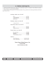
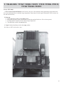
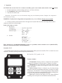
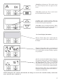
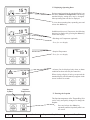
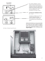
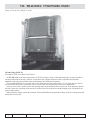
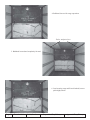
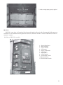
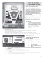
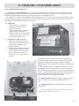
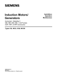
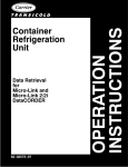
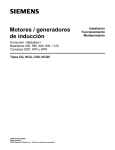
1
Page 2
Date: 1-12-06
Ed. 1, Rev. 0
Preparation: Terry Faherty
Approval: Terry Faherty
Totem Ocean Trailer Express, Inc.
INDEX
I.
TOTE Contact List
II.
Introduction
III.
Loading Operation Guide
IV. Trailers: TTOZ 592170 – 592239
Equipment: Carrier Gen Set UDC Reefer Unit UEE
A. Operation of Gen Set UDC
1. Location
2. Control Panel
3. Operation
B. Operation of Reefer Unit UEE
1. Location
2. Control Panel
3. Operation (w/gen set)
4. Operation (w/aux. power)
5. Stopping Instructions
C. Control Panel (analog)
1. Analog Controller-Partlow Combined
2. Analog Controller
3. Operation
V.
Trailers: TTOZ 743000 – 743039, TTOZ
593004 – 593132, TTOZ 592240 – 592292
Equipment: Carrier NEE 40/49
A. Description
B. Start Up
C. Stopping Instructions
D. NEE 40/49 Trailer Photo
VI. Trailers: TTOZ 743000 – 743039, TTOZ
593004 – 593132, TTOZ 592240 – 592292
Equipment: Thermo King CGII – M324
A. Description
B. Control Panel
C. Operation
Equipment: Refrigeration Unit NWE-MAX
A. Description
B. Control Panel
C. Operation
Equipment: Controller TG – V Microprocessor
A. Description
B. Control Panel
C.
D.
E.
F.
G.
Display Symbols and Control Keys
General Display Information
Displaying Operating Data
Entering the Setpoint
Thermo King CGII Trailer Photo
VII. Trailers: TTOZ594000 – 594011
Equipment: Thermo King SB-III-50
A. Description – Bulkhead Position
B. Control Panel
C. Operation
D. Thermo King SB-III-50 Trailer Photo
VIII. Trailers: TTOZ591000 – 591082
Equipment: Thermo King CSR40 Power Saver
A. Description and Photo of Trailer
B. Inspection
C. Starting Gen Set
D. Photo of 440 V
E. Starting the Refrigeration Unit
F. Stopping Instructions
G. Navigating the Controller Menu
H. General Operating Tips
I. Changing Thermostat Setpoint
J. Changing the Humidity Mode Setting
IX. Trailers:
TTOZ553001 – 553110
Equipment: Carrier Phoenix Ultra
A. Carrier Phoenix Ultra Trailer Photo
B. Description
1. Microprocessor Controller
2. Carrier Transicold Microporcessor Controller
C. Starting Instructions (automatic start)
D. Stopping Instructions
E. Control Panel
X. Trailers: TTOU540000 – 540029 and
TTOZ530000 – 530049
Equipment: Carrier 69NT40
A. Description
B. Inspection
C. Operation (w/aux. power)
D. Vents
E. Starting Instructions
F. Stopping Instructions and Photo of Trailer
G. Control Panel
3
I. TOTE CONTACTS
Totem Ocean Trailer Express, Inc., employees are particularly responsive to customers’ needs. Whatever question
you have, please give us a call at (800) 426-0074.
Please refer to the following list for TOTE phone numbers of key positions in the Anchorage/Fairbanks and Federal
Way/Tacoma offices.
Anchorage, Alaska: Area Code 907
Sales ..................................................... 265-7215
Cargo Operations ................................. 265-7221
Customer Service ................................. 265-7271
Maintenance ......................................... 265-7226
Fairbanks, Alaska: Area Code 907
Customer Service ................................. 452-1022
Federal Way, Wash.: Area Code 253
Sales ..................................................... 449-8131
Fleet ...................................................... 449-8215
Customer Service ................................. 449-8207
Tacoma, Wash.: Area Code 253
Pier Operations .................................... 238-8400
Dispatch ................................................ 238-8441
Maintenance ......................................... 238-8468
Claims & Quality Control ..................... 238-8490
Toll-Free:
Inside Washington ...................... 1-800-426-0074
Outside Washington .................... 1-800-234-0074
Totem Ocean Trailer Express, Inc.
On the Web
www.totemocean.com
Page 4
Date: 1-12-06
Ed. 1, Rev. 0
Preparation: Terry Faherty
Approval: Terry Faherty
II. INTRODUCTION
Totem Ocean Trailer Express, Inc., (TOTE) strives to deliver to you, the refrigeration customer, service that remains
unequaled in the shipment of perishable goods to the Alaskan market. Our ships (two Orca Class and three Ponce Class)
provide 68-hour transit time between Tacoma, Wash., and Anchorage, Alaska. There are two Orca Class sailings a week.
During the peak summer season, TOTE has the option of placing one or more Ponce Class ships into service to meet any
increase in seasonal demand.
TOTE operates a fleet of state-of-the-art refrigeration equipment offering 30-, 40-, 45- and 53-foot trailers. Also available
are our new 40-foot refrigerated containers. All refrigeration equipment is capable of maintaining temperature settings from
minus 20 degrees to 70 degrees Fahrenheit when the outside (ambient) temperature drops to minus 40 degrees Fahrenheit.
These trailers are equipped with several types of refrigeration units to meet and exceed all aspects of your particular
commodities.
• Carrier UDG/UEE
• Carrier NEE 40/49
• Thermo King CSR40 Power Saver
• Carrier 69NT40
• Thermo King CG-II/NWE MAX
• Thermo King SB III - 50
• Carrier Phoenix Ultra XL
This manual provides you, the customer, with the basic operational information necessary to set and control the environment
for your load and in turn for Totem Ocean Trailer Express to transport the cargo according to your specific instructions.
5
III. LOADING AND OPERATIONS GUIDE
When an empty reefer trailer or container is picked up from Totem Ocean Trailer Express, its refrigeration unit and
generator set (when so equipped) have been fully serviced (pre-tripped) and are ready for operation. All refrigeration units
have two potential sources of power including the self-contained electric standby units.
While in transit, the generator provides (230 or 460 vac) power supplied by an electrical plug connected to the receptacle
on the generator. The TK SBIII-50 and Carrier Phoenix Ultra self-contained units operate on their diesel engines. All dieselpowered equipment is provided with one full tank of fuel sufficient for 48 to 72 hours of operation. Additional fuel is at
customer’s expense.
While at the shipping facility, the unit can run on either its own diesel power or connected to user’s supplied power.
CAUTION: TOTE has mix-voltage requirements, either 230vac or 460vac, depending on equipment type.
TOTE also has a mix of top airflow and bottom airflow trailers. In both types, perishables requiring refrigeration must be
loaded to allow an airflow pattern with continuous lengthwise air channels between rows in every other layer. Diagramed
below is an example of a top airflow unit illustrating adequate product stacking pattern ensuring good air circulation throughout
the entire load.
In order to maintain a fresh appearance, prevent decay and extend the market life of most fresh fruits and vegetables, it
is necessary that the pulp temperature of the products vary not more than five degrees of the requested temperature setting
of the trailer. These sensitive chill commodities generate heat which must be removed while in transit. To accomplish this
requirement, the shipping unit must be pre-cooled prior to loading and the product must also be at or near the shipping
temperature. Pre-cooling is accomplished by setting the unit thermostat at the desired temperature and closing the doors for
20 minutes prior to loading.
Frozen foods should be stacked tightly together with spacing around the outside of the commodity to allow for airflow to
surround the load.
In the planning of refrigerated loads, do not load any product closer than nine inches from the top of the trailer. Also, the
cargo weight should be distributed evenly throughout the trailer.
NOTE: The trailer (or container) and commodity must be pre-cooled or frozen prior to loading. Transport units
are designed only to maintain commodity temperatures. The refrigeration unit should not be operating during
the loading process. Moisture in the air will cause ice to form on the evaporator coil and will restrict the cooling
capacity of the unit.
Page 6
Date: 1-12-06
Ed. 1, Rev. 0
Preparation: Terry Faherty
Approval: Terry Faherty
The loading of trailers is based on the following axle weights:
10,000#
34,000#
34,000#
42,000#
Driver’s Axle
Tandem Tractor Axles
Tandem Trailer Axles
Tri Axle Trailer set
Alaska has seasonal weight limits. Check with Alaska Cargo Operations (907-265-7221) for latest update.
After loading:
• Ensure the rear doors are properly closed and secured.
• Check the power cord to ensure it is plugged into the generator and all other cord are secured for transport.
• Start the generator set per operating instructions in this manual or on the unit cards. Turn on breaker.
• Turn on the refrigeration unit per instructions in this manual or on the unit cards.
CAUTION: Verify the temperature setting on the refrigeration unit is set correctly per shipping requirements.
For example, the temperature setpoint to be 32 degrees Fahrenheit is inadvertently set at 3.2 degrees Fahrenheit.
All temperature settings shall be in degrees Fahrenheit.
Check to ensure that the refrigeration unit is properly operating and the temperature is coming down within the set
temperature range.
NOTE: It is the loading facility’s responsibility to ensure that the reefer temperature is set to their requirement
before the driver accepts delivery of the load.
Points to Consider When Shipping Perishables – Shipper’s Responsibilities
DO’S
DO Make sure your product is at required transit
temperature prior to loading.
DO Check conditioning of trailer for leaks in walls, door
seals, etc. Be certain the floor is clean.
DO Start unit and set at required temperature. Be certain
“cool” light is on. Precool unit to the required transit
temperature with doors closed.
DO Call TOTE when reefer malfunction is suspected.
DO Shut off unit prior to loading.
DO Load van allowing proper air flow over, under
and around cargo.
DO Close and seal doors after loading and start the unit
immediately.
DO Call carrier for pickup as soon as loading is
complete.
DON’TS
DON’T Expect unit to cool your product to temperature
lower than that at which it was loaded.
DON’T Load trailer with holes in sides or roof, leaky
door seals or clogged floor air passages.
DON’T Load trailer prior to precooling.
DON’T Load trailer on which reefer unit won’t start.
DON’T Block air chute with cargo or obstruct air flow.
DON’T Load unit with reefer running.
DON’T Forget to restart unit after loading is complete.
DON’T Use trailer as cold storage.
DON’T Attempt to repair a unit you believe to be
malfunctioning.
Photo of unclean reefer floor, at right.
Unloading: It is the user’s
responsibility to return the
trailer or container to TOTE in
a clean condition. If special
framing, supports or blocking is
used in the conveyance of a
load it must be removed. All
debris should be swept out and
the floor channels free of
airflow restrictions.
7
IV. TRAILERS: TTOZ 592170–592239
Carrier, Gen Set, UDS and Carrier Refrigeration Unit UEE
A. Operation of Carrier UDG Undermount Diesel Gen Set
1.
2.
The unit is located on the right side of the trailer facing front. The 100-gallon fuel tank is sufficiently fueled to
operate the unit for approximately 48-72 hours. Additional fuel will be at the customer’s expense.
Photo of UDC #5
1.
2.
3.
4.
5.
6.
7.
Amp Meter
Glow Plug Switch
Start, Run, Stop
Running Time
Water Temperature
Engine Oil Pressure
Output Voltage
3. Operation of Gen Set (UDG)
a. Hold Glow Plug Switch (GPS) in the up position for 30 seconds (below zero degrees Fahrenheit, hold for
60 seconds). With GPS held in the up position, push the Start/Run/Stop switch to the start position.
b. After the engine has started, continue to hold the Glow Plug Switch (GPS) in the up position until the oil
pressure safety switch closes (when the oil pressure builds). The GPS will automatically be in the off
position when released.
c. Stopping Instructions: Push Start/Run/Stop switch to the stop position.
WARNING: Under no circumstances should ether or any other unauthorized starting aids be used in conjunction
with the glow plugs.
B. Operation of the Undermount Condensing Unit (UEE)
1. Unit is located on the left side of the trailer facing front.
2. Photo of UDC.
1.
2.
3.
4.
5.
6.
7.
8.
9.
Page 8
Date: 1-12-06
Ed. 1, Rev. 0
Preparation: Terry Faherty
S/S Start/Stop Switch
Power Light (white)
Manual Defrost Switch
Circuit Breaker
Cool Light (white)
Heat Light (amber)
Defrost (amber)
Suction Pressure
Running Time
Approval: Terry Faherty
3. Operating instructions (w/Gen Set).
a.
Connect Gen Set to Condensing Unit.
b.
Be sure Start/Stop switch is in the off position.
c.
Start Undermount Diesel Generator, then turn the Condensing Unit Start/Stop switch to start.
4. Operation with external power source.
a.
Check power source for proper voltage (230 vac, 3 phase, 60 hz)
b.
Made sure Start/Stop switch is in the stop position.
c.
Disconnect Gen Set power and connect external power.
d.
Turn Condensing Unit Start/Stop switch to start.
5. Stopping instructions.
a.
With Undermount Diesel Generator: Turn the Condensing Unit Start/Stop switch to stop.
b.
External power source: Turn off Condensing Unit Start-Stop switch. Check external power cord prior to
movement.
C. Control Panel (Analog)
The following two types of Analog Control are used on carrier units (592000 to 592249). Some 593 convertibles, and
743000 to 743019.
1.
Photo of Analog Controller-Partlow combined.
1.
2.
3.
4.
Temperature Control
Hot Gas Switch
Manual Defrost
Partlow Recorder
2. Photo of Analog Controller.
1. Total Hour Meter
2. Temperature Control
9
3. Used on various 593 convertible insul/reefers and 30-foot 743000-743019.
a. Analog Control Units are located on the front of the trailers.
b. With power applied (either Gen Set or external power) and the Condenser Start/Stop in the start position,
adjust the Analog Controller to the desired temperature: clockwise to a higher temperature and counterclockwise to a lower temperature. All temperatures are measured in Fahrenheit degrees. The 32 degrees
position is located at six o’clock.
c. The Partlow Temperature Recorder on all TOTE refrigeration trailers is a 30-day temperature recording
device with a renewable 30-day chart. New charts are placed in the recorder when the units are pre-tripped.
The charts remain the property of TOTE. It is okay to copy the chart. Please use care when reinstalling it in the
recorder.
Page 10
Date: 1-12-06
Ed. 1, Rev. 0
Preparation: Terry Faherty
Approval: Terry Faherty
V. TRAILERS: TTOZ 743000–743039, TTOZ 593004–593132,
TTOZ 592240–592292
Carrier NEE 40/49
A. The Carrier Transicold Models are all-electric, one-piece self-contained cooling and heating refrigeration units
for use on insulated trailers to maintain cargo temperatures from minus 20 to 80 degrees Fahrenheit. (These units are on
40- and 30-foot trailers.)
B. Start-up:
1. Check Start/Stop switch is in the stop position.
2. Inset power plug into 230vac power source (either the attached Gen Set or 230 vac shore power).
3. Set Temperature Controller for the desired cargo temperature.
4. Turn Start/Stop switch to the start position.
C. Stop: Push the Start/Stop switch to the stop position.
D. Photo of NEE 40/49 trailer front.
11
VI. Trailers: TTOZ 743000–743039, TTOZ 593004–593132,
TTOZ 592240–592292
Thermo King NWE Max Generator CGII – M324
A. Undermount Diesel Generators produce 230 volts, three-phase power at 60 cycles. They are self-contained with
110 gallons of diesel fuel. This is sufficient to operate the unit for approximately 48 to 72 hours. Additional fuel will be at
customer’s expense.
B. Photo of Generator CGII 2
1.
2.
3.
4.
5.
6.
Amp Gauge
On/Off Switch
Reset Switch
Preheat/Start Switch
Hour Meter
Alternator Switch
C. Operation – CGII Starting
CAUTION: Be sure power cord is connected to refrigeration unit and the NWE MAX power switch is in the
off position.
1. Push Preheat/Start switch to preheat and hold 30 seconds above zero degrees Fahrenheit (below zero degrees
Fahrenheit, hold for 60 seconds).
2. While holding the Preheat switch in preheat, switch On/ Off Switch to on.
3. Switch the Preheat/Start switch to the start position.Release
when engine starts. Do not release the switch
prematurely when the engine is extremely cold.
WARNING: Under no circumstances should either or any other
unauthorized starting aids be used in conjunction with glow plugs.
4. After engine start:
a. Listen for abnormal noises.
b. Engine oil pressure (gauge located on other end of Gen
Set from the control panel) should read 30 to 80 psi.
Refrigeration Unit NWE-MAX
A. The NWE- MAX is a 230 volt, three-phase unit that can operate
on the trailer’s self-contained generator or on auxiliary power.
B. Photo of NWE-MAX #1 digital, at right.
1. Digital Thermometer
2. Indicator Lights:
white = cool
tan = defrost
amber = heat
green = on
3. Engine Hour Meter
Page 12
Date: 1-12-06
4.
5.
6.
7.
8.
TG-5V
On-Off
Manual Defrost
Phase Light
Digital Temp On-Off
Switch
Ed. 1, Rev. 0
Preparation: Terry Faherty
Approval: Terry Faherty
C. Operation
CAUTION: Do not start Gen Set or connect to auxiliary power source unless unit switch is in the off position.
1. Set unit temperature to desired setting (not lower, it will not cool faster).
2. Set Continuous Cycle switch in desired position.
3. Turn On-Off switch to on.
Remember: If unit fails to run, the thermostat setting may not demand operation. Compare box temperature
with thermostat setting.
WARNING: Visually check refrigeration unit operation every six to 12 hours. Do not rely on sound.
4. On many units the sound of the Gen Set will suppress the sound of the fan (look for blowing ribbon) and the
compressor (check the indicator lights).
Some of the items to check:
a. Reefer unit
Temperature ........................ set point versus actual
Circuit Breaker ................... on _____ off _____
Indicator Lights ................... white - cooling
tan - defrost
amber - heat
green - on
b. Gen Set
Oil Pressure _____
DC Amps _____
Fuel Level _____
Coolant Temp _____
A/C Output _____
These checks are a recommended minimum. If there is a problem, contact customer service (800-426-0074)
and your call will be directed to TOTE maintenance.
Controller TG-V.
A. TOTE has supplied the latest in Thermo King Programmable Micro processor controller TG-V to control our newer
equipment. It displays operating information quickly and accurately.
B. Controller TG-V graphic, at left.
Features include:
• Thermometer. Displays return air temperature and (optional)
discharge air temperature with one-tenth of a degree of accuracy.
• Thermostat. Provides temperature control from minus 20 to 80
degrees Fahrenheit or minus 28 to 28 degrees Celsius, in five-tenths
degree increments.
• Defrost control. Defrost is initiated every four hours during
pull-down until cargo compartment temperature is in range. At in-range
temperatures, the controller is factory programmed to initiate defrost
every four hours, but may be reprogrammed, by a Thermo King dealer,
for two to 16 hour intervals in two-hour increments.
• Fuel saver. Can detect and display up to four alarm conditions
including sensor microprocessor and defrost termination failures.
13
C. Display Symbols and Control Keys
Showing is a list of the display symbols and control keys used in the Programmable Microprocessor Controller TG-V. It
is recommended that you become completely familiar with the meaning of each symbol and the function of each control key
before operating the unit.
s
10 .8F
s
s
15 .7F
s
• Return Air Symbol (arrow returning from
thermometer to unit). Indicates the return air
temperature is being displayed.
• Setpoint Symbol (hand pointing to thermometer).
Indicates the set point temperature is being displayed.
-05 .5F
20
!
s
Page 14
C
.5
15 .7F
Date: 1-12-06
Ed. 1, Rev. 0
• Discharge Air Symbol (arrow from unit pointing at
thermometer). Indicates the discharge air temperature
is being displayed (optional).
• Minus Sign. Indicates the temperature being
displayed is below zero degrees.
F
C
20
.5
!
• Fahrenheit Symbol (degree symbol and letter F).
Indicates the temperature being displayed is in degrees
Fahrenheit.
• Celsius Symbol (degree symbol and letter c).
Indicates the temperature being displayed is in degrees
Celsius.
• Temperature. When a temperature symbol is
displayed:
a. Large numbers indicate the temperature
is whole degrees.
b. A decimal point and half-size number
indicate temperature in tenths of a degree.
•Alarm Symbol (exclamation point within a triangle).
When this flashing symbol is displayed, an alarm (fault)
condition has been detected by the controller.
• Alarm Code. When an alarm has been sensed and
an alarm screen has been selected by pressing the
Select Key, this two-digit code indicates the type of
alarm.
Preparation: Terry Faherty
Approval: Terry Faherty
!
04
• Select Key (cycling arrows). This is used to select
the various displays which can appear on the
screen.
• Enter Key (equals sign). This is used to enter
new information into the controller.
• Up Key (arrow pointing upward). When the
Setpoint Symbol is on the screen, this key is used
to increase the Setpoint temperature.
• Down Key (arrow pointing downward). When
the Setpoint Symbol is on the screen, this key is
used to decrease the Setpoint temperature.
D. General Display Information
With the Thermo King Unit switched off, the
controller screen will be dark; nothing will be on
the display.
!
s
s
-88
15
F
.8
When the Thermo King Unit is switched on, all
symbols and readouts will be displayed for about
five seconds. Make sure that all display segments
are operational.
F
.7
After five seconds, the standard display will appear.
This display remains on the screen during normal
operation. The standard display is set to Return
Air Temperature at the factory, however, the
controller can be programmed to Show Discharge
Air, Return Air or Setpoint as the standard display.
When the Thermo King unit is switched off, it is
normal for the display to remain on for about 30
seconds as it slowly fades.
NOTE: With power off, or battery disconnected, all settings are saved in the controller memory and become
active when the unit is switched on.
15
E. Displaying Operating Data
s
15
F
.7
During normal operation, the standard display is on
the screen. Return Air Temperature is the factory
standard display setting (this may be changed).
Other operating data can also be displayed.
To view other operating data, repeatedly press and
release the Select key.
15
10
FF
.8
.7
In addition to Return Air Temperature, the following
data may be displayed by pressing the Select key
for the next display:
s
• Discharge Air Temperature (optional)
Press for next display.
15
!
Setpoint
Symbol
• Setpoint Temperature
F
.5
Press for next display.
• Alarms (Can be displayed only when an alarm
condition has been sensed by the controller.)
04
When viewing a display, if no keys are pressed, the
standard display will automatically reappear on the
screen in about 10 seconds.
Setpoint
Temperature
F. Entering the Setpoint
-05
F
.0
The Setpoint temperature of the Thermo King Unit
can be easily and quickly changed. To change the
Setpoint:
1.
Page 16
Date: 1-12-06
Ed. 1, Rev. 0
Press and release the Select key
repeatedly until the Setpoint Symbol is on
the screen.
Preparation: Terry Faherty
Approval: Terry Faherty
New Setpoint
Temperature
10
F
.5
2. Press the Up or Down key until the
setpoint is at the desired temperature
setting. Pressing and releasing either key
repeatedly will cause the temperature to
change by five-tenths of a degree for each
key press. Holding either key down will
cause the temperature to scroll
automatically, one degree at a time.
3. To enter the new setpoint into memory,
press and release the Enter key within
five seconds.
s
-01 .4F
G. Photo of Thermo King CGII trailer.
• The display will blink once as the new
setpoint is entered into memory.
• The new setpoint will remain on the
screen for about five seconds, then …
• The standard screen will automatically
appear.
Caution: If the Enter key is not pressed within
five seconds, the original setpoint will appear
on the screen for five seconds, the standard
screen will automatically appear, and the
Thermo King Unit will be controlled at the
original setpoint.
17
VII. TRAILERS: TTOZ594000–594011
Photo of Thermo King SB-III 50 trailer.
Thermo King SB-III 50
Provided by TOTE in 40’ Duel Temp Trailers
A. The 594 series is the latest advancement in TOTE’s original version of the dual temperature concept introduced
into the Alaska trade in the early-1980s. It is a 40-foot trailer equipped with a moveable, suspended, and insulated
bulkhead which, when lowered and secured, will maintain two isolated environments.
The suspended bulkhead is on a track from 12 feet back from the front of the trailer to 27 feet back from the front of
the trailer. This allows for a custom mix of freeze loads in the nose and chill loads in the rear compartment.
Once the freeze load is loaded, release the securing straps on the bulkhead and lower the rear of the unit down against
the floor. Secure the restraining locks into the E-track on each side of the trailer and the loading of the chill product can
proceed without delay.
When unloading, simply unlatch the restraints, lift the bulkhead back up against the ceiling, cinch the securing straps and
unload the freeze pouch.
Page 18
Date: 1-12-06
Ed. 1, Rev. 0
Preparation: Terry Faherty
Approval: Terry Faherty
Warning: Bulkhead must be stowed before moving empty trailer.
1. Bulkhead in raised (stowed) position, safe.
2. Stowing strap loose, unsafe.
3. Stowing strap secure.
19
4. Bulkhead lowered for cargo seperation.
Trailer midpoint lines.
5. Bulkhead lowered and completely forward.
6. Load securing strap and E track latched, but not
pulled tight, unsafe.
Page 20
Date: 1-12-06
Ed. 1, Rev. 0
Preparation: Terry Faherty
Approval: Terry Faherty
7. Load securing straps properly applied.
SB-III-50
SB-III-50 is a one-piece, self-contained, diesel-powered heating/cooling unit with a Programmable Microprocessor
Controller. It is self-contained with 110 gallons of diesel fuel, sufficient to last 48 to 72 hours. Additional fuel will be at
customer’s expense.
B. Photo of SB-III-50 controller.
1.
2.
3.
4.
5.
6.
7.
8.
9.
10.
11.
Engine Hour Meter
Rear Controller
Front Controller
Oil Pressure
Engine Temperature
Amp Meter
Engine Reset
On-Off Switch
Preheat-Start Switch
Manual Defrost
Diesel-Electric Switch
21
C. SB-III-50 Operation.
1. Set the unit On/Off switch to the on position. Hold the Preheat/Start switch in the preheat position. (If ambient
temperature is greater than 32 degrees Fahrenheit, do not hold preheat; if ambient temperature is zero to 32
degrees Fahrenheit, hold for 30 seconds; and if ambient temperature is below zero degrees, hold for 60 seconds.)
Note: The amp meter should show a discharge of approximately 28 to 29 amps.)
2. Hold the Preheat/Start switch in the start position. The engine should begin cranking. Hold the switch in the start
position until the unit is running on its own. (Note: No not release the switch from the start position prematurely
when the engine is extremely cold.)
3. Adjust the controller setpoint to the desired load temperature (front compartment first). To change the setpoint:
a.
Press and release the Select key until the Setpoint Symbol is on the screen.
b.
Change the setpoint with the Up and Down keys.
c.
Enter the setpoint within five seconds with the Enter key.
Note: For more detail on the TG-V microprocessor, see Section C of II NWE MAX.
4. Temperature restrictions for both front and rear compartments:
Rear
Chill
Okay
KFF
Okay
Dry
Okay
KFF
Okay
Dry
Okay
Chill
Okay, with at least eight degrees lower in front.
Freeze
No
Please note that if bananas are loaded in dual temp reefers, it is entirely at the shipper’s own risk. This is due to
sensitivity and narrow temperature range required for bananas.
Page 22
Date: 1-12-06
Ed. 1, Rev. 0
Preparation: Terry Faherty
Approval: Terry Faherty
VIII. TRAILERS:
TTOZ591000–591082
Thermo King CSR40 Power Saver
A. The Thermo King Unit in 45-foot
refrigeration trailers is offered by TOTE. They
are a one-piece, self-contained, all-electric unit,
using a state-of-the-art scroll compressor, which
includes heating and cooling systems managed by
an MP-3000 controller that provides precise
temperature direction between minus 20 and 84
degrees Fahrenheit.
The trailers are equipped with a Thermo King
CGSM Undermount Diesel Generator with an 85
gallon tank capable of maintaining power for 6072 hours. TOTE provides a full tank of fuel
sufficient for normal pre-cooling and transport.
Additional fuel will be at customer’s expense.
B. Inspection
1. Check interior of trailer for cleanliness
and clear airflow channels on the floor.
2. Check trailer panels, insulation and door
seals for damage. If damage is found,
do not use the unit. (If defects are
found, notify Totem Ocean Trailer
Express.)
C.
1.
2.
3.
4.
Starting Generator Set
Ensure there is not a load on the generator (and the refrigeration unit is in the “0,” off, position).
Turn Gen Set Off/On switch to the “I” (on) position.
Push the Preheat/Start switch to preheat. (Control panel should show a 25 to 30 amp discharge.)
Push the Preheat/Start switch to start. Release the switch when it starts. (Hold long enough to ensure engine
start.)
D. Photo of 440 V, left.
E. Starting the refrigeration unit and
setting the MP-3000.
1.
Check the unit On/Off Switch to the
off position.
2. Connect the power cord to the proper
power source.
a.
Generator: Connect yellow 460
vac to black 460 vac Gen Set
cord. Start Gen Set.
b.
460 vac: Connect yellow cord
directly.
c.
230 vac: Connect grey transformer line to 230 vac power source. Ensure yellow 460 cord is plugged into
transformer.
3. Switch the unit On/Off switch to the on position.
4. Adjust MP300 controller to the desired setpoint temperature:
a.
Press Setpoint key to display cursor flashing in the “Temp Set” line.
b.
Press F4 key.
c.
If needed, enter a minus sign by pressing the “Exit” key. Press numeric keys to enter the new setpoint.
d.
Press and hold the F4 key until cursor stops flashing.
23
F. Stopping instruction. Place “Run/Stop” switch in the stop position to stop the unit.
G. Navigating the Controller Menu
The Controller Main Menu is divided into seven major menus:
• Setpoint
• Data
• Alarm List
• Commands
• Misc. Functions
• Configuration
• Data-Logger
• RMM (Removable Monitoring Modem) State
Moving through these seven menus and their submenus and entering commands requires the use of four text keys: F1,
F2, F3 and F4 keys.
H. General operating tips
To quickly change the display temperature units between
Celsius (C) and Fahrenheit (F), press and hold the C/F key,
then press the Setpoint key for one second.
F1 Key: Press the F1 key each time you want to exit a
submenu and/or retrieve current system data for display.
F2 or F3 Key: Press the F2 or F3 key each time you
want to scroll up or down to view another item in a menu or
submenu, or to scroll forward or backward in a menu line.
F4 Key: Press the F4 key to enter a new menu or
submenu, to access a menu line to enter information, or to load
a command or value.
Pressing the Setpoint key displays a list of tasks and
values that can be activated or set.
•Setpoint Temperature: Set the controller setpoint.
• Humidity Control: Activates the dehumidify mode.
• Humidity Setpoint: Sets the humidity setpoint.
• Economy Mode: Activates the economy mode.
I. Changing Thermostat Setpoint
Press the Setpoint key. Cursor appears in the “Temp
SetP” line. Press F4 key – an enter arrow appears in the
menu line and current setpoint using the general purpose
keypad. To enter a minus setpoint, press the Exit (+/-) key
first. Press and hold the F4 key until the cursor stops
flashing. The new setpoint is recorded in the controller and
appears in the LCD display.
Note: If the F4 key is not pressed within 30 seconds,
the controller will default to the previous setpoint.
J. Changing the Humidity Mode Setting
Press the Setpoint key. Press F2 key to scroll to “Hum
Control” line. Press F4 key and the cursor moves to the end
of the menu line and flashes. Press F2 key to toggle between
off and on. With the desired state in the menu line, press and
hold the F4 key until the cursor stops flashing. Press the
“Esc” key to exit the setpoint screen.
Page 24
Date: 1-12-06
Ed. 1, Rev. 0
Preparation: Terry Faherty
Approval: Terry Faherty
IX. TRAILERS: TTOZ553001–553110
Carrier, Phoenix Ultra
A. Photo of Phoenix Ultra trailer front.
B. The unit is a one-piece, self-contained, fullycharged, pre-wired, refrigeration/heating
“nosemount” diesel-powered unit (with electric
standby) for use in insulated trailers to maintain
cargo temperatures within very close limits.
TOTE provides these in the 53-foot trailers:
1. Microprocessor Controller: The
Microprocessor Controller is housed in
the control panel on the lower roadside
corner of the unit. This controller consists
of two control boards and a relay module:
a. The Processor Board includes the
microprocessor program memory,
and necessary input-output circuitry
to interface with the unit.
b. The Display Board is mounted in
the same control box as the
processor board. The display board
includes the LCD display, keypad
and keypad interface.
c. The Relay Module contains
replaceable relays, diode blocks and
fuses, along with the wiring harness.
The microprocessor is totally self-contained and
does not contain any serviceable components.
CAUTION: Under no circumstances should anyone attempt to repair the Logic or Display Boards! Should a
problem develop with these components, contact your nearest Carrier Transicold dealer for replacement.
2. The Carrier Transicold Microprocessor Controller incorporates the following features:
a. Control supply or Return Air Temperature to tight limits by providing refrigeration control, heat and defrost to
ensure conditioned air delivery to the load.
b. Dual independent readouts of set point and supply or return air temperatures.
c. Digital readout and ability to select data.
d. A pre-trip checkout of refrigeration unit operation.
e. A self-test check on program memory and data memory. The self-test is executed each time the system is
switched from “stop” to “start.” Errors, if any, shall be indicated on the display as an “ERR.X,” where “X” is
a number corresponding to the number of the test. The unit shall display this error for five seconds and then
reset the micro.
C. Starting instructions (automatic start)
1. Place the Run/Stop switch in the run position. The micrprocessor will perform a self test (all display messages
will appear in display window). Then the setpoint and box temperature will be displayed.
2. The microprocessor will energize the glow cycle (length of time depends on the engine temperature) Engine will
start automatically. The engine will run in the low speed for 15 seconds, or until the engine coolant temperature
exceeds 79 degrees Fahrenheit.
3. To change the set point press the “Up” or “Down” arrow on the controller, and press the “Enter.”
4. Pressing the “Auto S/S – Continuous” key changes the operation of the unit between automatic start/stop (unit
will automatically start and stop in response to changing box temperature) or automatic start/continuous run (unit
will operate continuously after starting).
25
D. Stopping instruction.
Place “Run-Stop” switch in the stop position to stop the unit.
E. Photo of Phoenix Ultra control panel.
Page 26
Date: 1-12-06
Ed. 1, Rev. 0
Preparation: Terry Faherty
Approval: Terry Faherty
X. TRAILERS: TTOU540000–540029
Carrier 69NT40 Refrigeration Unit
A. The Carrier Transicold model in the 40-foot refrigeration container is offered by TOTE. Constructed of light
weight aluminum, the unit is designed to serve as the trailer’s front wall. They are one-piece, self-contained, all-electric
units which include heating and cooling systems to provide precise temperature control.
The controller is a Carrier Transicold Micro-Link 3 Microprocessor. The controller will operate automatically to select
cooling, holding or heating as required to maintain the desired set point temperature within very close limits. The unit is
also equipped with a mechanical temperature recorder.
B. Inspection
1. Check interior of container for
cleanliness and clear airflow
channels on the floor.
2. Check container panels, insulation
and door seals for damage. If
damage is found, do not use the unit.
(If defects are found, notify Totem
Ocean Trailer Express, Inc.)
C. Connection to 460 vac power
1. Make sure Start/Stop switch (ST,
on control panel) and circuit breaker
(CB-1 in the control box) are in
position “0” (off).
2. Plug the 460vac (yellow) cable into
a de-energized 380/460 vac power
source. Energize the power source.
Place circuit breaker (CB-1) in
position “I” (on). Close and secure
the door.
D. Vents. Units are equipped with fresh air mixing vents.
The purpose of this vent is to provide fresh air mixing for the
transport of commodities that require fresh air circulation.
Transporting of frozen commodities requires the vent to be fully
closed.
Two slots and a stop are designed into the disc for air flow
adjustments. The first slot allows for a zero to 30 percent air
flow, and the second slot allows for a 30 percent to 100 percent
airflow. To adjust the percentage of airflow, loosen the wing nut
and rotate the disc until the desired percentage of air flow
matches with the arrow. Tighten the wing-nut.
E. Starting the unit. With power properly applied, and the
fresh air damper set, place the Start-Stop Switch to “I”
(on).
F. Stopping the unit. Place Start-Stop Switch in the “O”
(off) position.
Photo of Carrier 69NT40 controller, above. Carrier
69NT40 trailer front photo, at left.
27
Page 28
Date: 1-12-06
Ed. 1, Rev. 0
Preparation: Terry Faherty
Approval: Terry Faherty