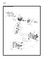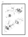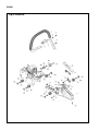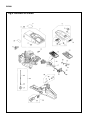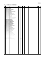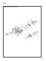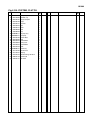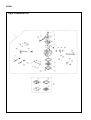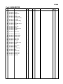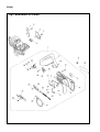
1
848C8C93A1 (506)
CHAIN SAW
G5200
NOTE :
1. Use KOMATSU ZENOAH genuine parts specified in the parts list for repair and/or replacement.
2. KOMATSU ZENOAH does not warrant the machines, those which have been damaged by the use
of any parts other than those specified by the company.
3. When placing orders of parts for repair and/or replacement, check if the model name and the serial
number are suitable to those specified in the parts list, then use parts number described in the
parts list.
4. The contents described in the parts list may change due to improvement.
5. The parts for the machine shall be supplied within ten (10) years after the machine is discontinued.
[It is possible that some specific parts may be subject to change of their delivery term and list price
within the limit of ten (10) years after the machine is discontinued. And it is also possible that some
parts may be available even after the limit of ten (10) years.]
APPLICABLE SERIAL NUMBERS : 303107 and up
June 2005
G5200
Fig.1 POWER UNIT
G5200
Fig.1 POWER UNIT
Key# PART NUMBER
1
2
3
5
6
7
8
9
10
11
12
13
14
15
16
17
18
19
20
21
22
23
24
25
26
27
28
29
30
31
32
33
34
35
36
37
38
39
40
DESCRIPTION
2880-12111 Cylinder
2880-14111 Inlet Pipe
2880-14120 Spring
2880-14150
2670-14311
2670-14320
2880-14350
2880-14361
2670-14211
4820-13180
2810-15220
2850-15230
2810-15113
2670-14130
3356-15210
2810-15310
848C802101
3356-21130
T4012-21240
04065-03515
2670-21210
2670-21220
2850-21230
2670-21250
2810-22511
2810-22521
848C8021D2
2670-21320
2810-22210
3310-82230
2810-22411
2880-41110
2880-41210
2880-41310
3350-41320
1400-41410
2670-41510
848C8A4202
1000-43240
Inner Guide
Bracket
Screw M5x14
Spacer
Gasket
Gasket, Cylinder
Bolt, Cylinder M5x20
Bolt, Muffler M5x83
Nut, Muffler M5
Muffler
Screw M5x10
Gasket, Muffler
Cover
Crankcase assy
• Spring Pin
• Bearing 15x35x11
• Snap Ring ø35
• Oil Seal 15x35x4.5
• Oil Seal 15x28X4.5
• Stud
• Elbow
• Stopper
• Stopper
Gasket, Case
Screw M5x25
Pipe 3x7x105
Clip
Mat
Piston ø45
Piston Ring ø45
Piston Pin 7.4x11x37.5
Snap Ring
Needle Bearing 11x15x12.3
Washer
Crankshaft Comp.
Key
Q'TY
/UNIT NOTE
1
1
1
1
1
2
1
1
1
4
2
2
1
2
1
1
1
3
2
1
1
1
2
1
1
1
1
5
1
1
1
1
2
1
2
1
2
1
1
ø45
Key# PART NUMBER
DESCRIPTION
Q'TY
/UNIT NOTE
G5200
Fig.2 IGNITION, STARTING
G5200
Fig.2 IGNITION, STARTING
Key# PART NUMBER
1
2
3
4
5
6
7
8
9
10
11
12
13
14
15
2670-71101
1850-75220
2670-71130
0308-00040
3350-43231
0290-20820
2880-71300
2810-71204
2810-71220
2670-71230
2810-72110
1400-72121
2670-71320
2810-71250
2670-14220
DESCRIPTION
Rotor assy
• Ratchet
• Spring
• Ring
Nut M8
Washer M8
Coil Assy
• Coil Comp.
• • Cord
• • Grommet
• Plug cap
• Spring
• Tube
• Grommet
Screw M5x20
Q'TY
/UNIT NOTE
1
2
2
2
1
1
1
1
1
1
1
1
1
1
2
18 2670-71510 Cord
19 2880-71600 Switch assy
20 2810-71610 • Switch
21 2670-71621 • Switch Cover
22 2880-71630 • Plate
23 2670-14130 Screw M5x10
24 3699-90512 Spark plug (NGK BPM8Y)
25 2810-21270 Plate
26 0260-30410 Screw M4x10
27 2881-75000 Starter assy
28 2810-75110 • Recoil case comp.
29 2810-75120 • Guide
30 2810-75150 • Boss
31 2670-75212 • Reel
32 3317-75300 • Spring comp.
33 2670-75411 • Rope
34 T2041-75420 • Knob
35 T2041-75431 • Collar
1
1
1
1
1
1
1
1
2
1
1
1
1
1
1
1
1
2
37
38
39
40
1
1
1
1
2881-75440
1400-86280
2670-14220
2880-75600
• Spring B
• Washer
• Screw
Fan cover comp.
42 2880-75620 • Sheet
43 2670-14320 Screw
44 848C8C90C1 Label, Recoil
45 2881-98611 Snow protector
1
4
1
1
OP
Key# PART NUMBER
DESCRIPTION
Q'TY
/UNIT NOTE
G5200
Fig.3 HANDLE
G5200
Fig.3 HANDLE
Key# PART NUMBER
1
2
3
4
5
6
7
8
9
10
11
12
13
14
15
16
17
18
19
20
21
22
23
24
25
26
27
28
29
2880-32101
8488251901
2880-32250
2670-14130
2880-32270
2880-31211
2810-33007
3330-33250
3310-33262
3310-33271
2810-33280
2670-75520
2810-33211
2670-33311
3356-33321
04025-00524
848C3033E3
2670-34110
8488251901
2810-25210
2670-14320
2880-35111
8488251601
2810-35150
2881-35110
2881-35120
2880-35211
3350-35170
2880-35250
DESCRIPTION
Left handle comp.
Screw M5x19 BT
Bracket
Screw M5x10
Screw M5x8
Damper
Right handle assy
• Stopper
• Spring
• Knob
• Damper (A)
• Screw
• Gasket
• Throttle lever
• Throttle spring
• Spring pin ø5.2x24
Arm
Grip cover
Screw M5x19 BT
Chain catcher
Screw M5x14
Damper
Screw M5x16 BT
Damper cap
Spring
Spacer
Damper
Bolt
Cap
Q'TY
/UNIT NOTE
1
4
1
1
1
1
1
1
1
1
1
1
1
1
1
1
1
1
1
1
1
3
4
3
1
1
2
2
2
Key# PART NUMBER
DESCRIPTION
Q'TY
/UNIT NOTE
G5200
Fig.4 FUELING SYSTEMS
G5200
Fig.4 FUELING SYSTEMS
Key# PART NUMBER
DESCRIPTION
1 2880-31101 Cylinder cover
2 2880-31120 • Nut
3 2670-14320 Screw M5x14
4 2854-31513 Label
5 2810-83305 Cleaner cover comp.
6 3356-83322 • Knob
7 3388-83340 • Gasket, cap
8 2810-83500 • Air cleaner comp.
9 2810-83520 • • Seal
10 1600-33130 • Screw
11 2810-83410 • Grommet, Air cleaner
12 2810-83101 Air cleaner comp.
13 2813-31210 Label
14 2880-82310 Guide ( I )
15 2880-82350 Guide (HL)
16 2880-82102 Manifold comp.
17 2810-82141 Supporter
18 2880-82210 Screw M5x52
19 2880-82410 Choke rod
20 2670-82421 Grommet, Choke
21 2670-82430 Guide
22 2880-82511 Throttle rod
23 2810-82520 Grommet, throttle
24 848C808536 Fuel pipe assy
25 848C8085R5 • Fuel pipe
26 2850-34350 • Collar
27 3302-85400 • Filter assy
28 2670-34401 Tank cap assy
29 2670-34430 • Gasket, Tank cap
30 2670-34500 Breather assy
31 3350-34540 • Pipe
32 1260-85460 • Clip
33 T2041-75810 Label
34 2811-98501 Air cleaner comp.
Q'TY
/UNIT NOTE
1
1
5
1
1
1
1
1
1
1
1
1
1
1
1
1
1
1
1
1
1
1
1
1
1
1
1
1
1
1
1
1
1
1
OP(Felt)
Key# PART NUMBER
DESCRIPTION
Q'TY
/UNIT NOTE
G5200
Fig.5 OIL SYSTEM, CLUTCH
G5200
Fig.5 OIL SYSTEM, CLUTCH
Key# PART NUMBER
DESCRIPTION
1 2841-31801 Oil cap assy
2 2841-31820 • Gasket, cap
3 2670-23101 Oil pipe compete
4 2670-23120 • Pipe
5 2670-23131 • Oil filter
6 2670-23210 Pipe
7 3330-23121 Valve
8 3350-26220 Seal
9 3350-26230 Clip
10 848C806711 Oil pump assy
11 848C8067A1 • Oil pump
12 2670-55120 • Worm Gear
13 2670-55220 Seal
14 2670-55410 Screw M4x14
15 2670-55610 Pump cover
16 2670-55410 Screw M4x14
17 2670-51210 Plate
18 848C805121 Clutch assy
19 3317-51220 • Clutch shoe
20 3317-51231 • Spring
21 2810-51310 Needle bearing 12x15x14
22 2880-51110 Clutch drum
23 3350-51121 Rim 325P
Q'TY
/UNIT NOTE
1
1
1
1
1
1
1
1
1
1
1
1
1
2
1
3
1
1
3
1
1
1
1
Key# PART NUMBER
DESCRIPTION
Q'TY
/UNIT NOTE
G5200
Fig.6 CARBURETOR
G5200
Fig.6 CARBURETOR
Key# PART NUMBER
DESCRIPTION
Q'TY
/UNIT NOTE
1
2
3
4
5
6
7
8
9
10
11
12
13
14
15
16
2880-81001
3306-81380
2810-81120
3310-81130
3304-81140
1172-81150
2810-81170
1491-81160
3310-81230
3310-81240
1262-81270
3310-81250
3310-81280
3310-81260
3310-81290
3356-81310
Carburetor assy
• Screen
• Pump cover
• Screw
• Gasket, pump
• Diaphragm, pump
• L needle
• L needle spring
• Lever
• Screw M lever pin
• Spring
• Pin, lever
• Cover
• Diaphragm assy
• Gasket
• Valve, inlet
1
1
1
1
1
1
1
1
1
1
1
1
1
1
1
1
18
19
20
21
22
23
24
25
26
27
28
29
30
31
32
33
3356-81340
2670-81410
2880-81420
2630-81460
2670-81430
2880-81331
3080-81320
3310-81351
2880-81460
1148-81390
3350-81350
3350-81220
2670-81450
2810-81440
2880-81470
2810-06021
• Throttle valve
• Throttle spring
• Throttle shaft
• Idle spring
• Idle screw
• H needle
• H needle spring
• Screw
• Choke shaft
• Ring
• Choke spring
• Boll
• Choke valve
• Throttle lever
• Screw, valve
Gasket Kit
1
1
1
1
1
1
1
4
1
1
1
1
1
1
3
1
WT-281A
Key# PART NUMBER
DESCRIPTION
Q'TY
/UNIT NOTE
G5200
Fig.7 BREAKING SYSTEMS
G5200
Fig.7 BREAKING SYSTEMS
Key# PART NUMBER
DESCRIPTION
1 2670-25310 Bumper
2 2670-14320 Screw M5x14
3 2810-25421 Plate
4 2670-25430 Screw M4x10
5 2670-25410 Guide
6 3350-53410 Nut M8
7 2881-54003 Chain cover assy
8 848C8053A5 • Chain cover
9 2880-53150 • Stopper
10 2671-53210 • Screw
11 2810-53221 • Nut
12 2671-53230 • Gear
13 2671-53240 • Plate
14 2670-25410 • Guide
15 2670-54630 • Screw M4x12 BT
16 2671-53311 • Protector
17 2880-54112 • Front guard
18 2670-54121 • Pin
19 0308-00030 • Ring
20 2670-54210 • Spring
21 2670-54220 • Pin
22 2670-54231 • Spacer
23 3238-15230 • Washer
24 0308-00040 • Ring
25 2810-54240 • Plate
26 2810-54260 • Spacer
27 2670-54621 • Cover
28 2670-54630 • Screw M4x12 BT
29 2670-54302 • Brake lever comp.
30 2670-54411 • Slide arm
31 2670-54510 • Brake band
32 3356-24140 • Roller
33 2670-54610 • Brake spring
34 2880-54650 • Return spring
35 848C8C90B1 Label, Chain cover
Q'TY
/UNIT NOTE
1
2
1
1
1
2
1
1
1
1
1
1
1
1
2
1
1
1
1
1
1
1
1
2
1
1
1
3
1
1
1
1
1
1
1
Key# PART NUMBER
DESCRIPTION
Q'TY
/UNIT NOTE
G5200
Fig.8 GUIDE BAR, SAW CHAIN, TOOLS
G5200
Fig.8 GUIDE BAR, SAW CHAIN, TOOLS
Key# PART NUMBER
DESCRIPTION
1
2974-52111 Hard nose bar 18”
2 3646-52113-50 Sprocket nose bar 18”
3 3646-52210-50 Chain 18”(21BP-72E)
Q'TY
/UNIT NOTE
1
1
1
10
3356-97110 Protector
1
13
14
15
16
17
18
19
20
21
22
23
24
25
26
27
28
29
30
31
32
33
34
35
36
37
38
2811-91000
3345-91110
3320-91140
2670-91150
3320-97310
3317-91210
3381-91530
3310-91540
2670-96002
2890-96100
2670-96210
2670-96220
3350-96230
2670-96240
2670-96310
2670-96320
2670-96510
3350-96620
2670-96660
3350-96240
2850-96410
2810-96710
3317-91300
3317-91400
2881-98710
2881-98720
1
1
1
1
1
1
1
1
1
1
1
1
1
3
1
1
1
1
1
1
1
1
1
1
3
2
Tool set
• Bag
• Plug wrench 13x19
• Driver
• File ø4.8 (3/16”)
• File
• Grip
• Gauge
Tool set
• Puller Assy (for rotor)
• Wrench (for clutch)
• Stopper (for piston)
• Guide (for piston)
• Wrench (for clutch assy)
• Wrench (M5)
• Wrench (M4)
• Guide (for brake spring)
• Guide
• Holder
• Gauge
• Wrench
• Guide (for brake spring)
Fuel tank assy
Oil tank assy
Front damper
Rear damper
G: .058”
G: .058”
OP
OP
OP
OP
OP
OP
OP
OP
OP
OP
OP
OP
OP
OP
OP
OP
OP
OP
Key# PART NUMBER
DESCRIPTION
Q'TY
/UNIT NOTE
1-9 Minamidai, Kawagoe, Saitama, 350-1192 Japan
PRINTED IN JAPAN
PRINTED ON RECYCLED PAPER
IMPRIMÉ SUR PAPIER RECYCLÉ
GEDRUCKT AUF RECYCLING PAPIER
STAMPATO SU CARTA RICICLATA
IMPRESO EN PAPEL RECICLADO