1
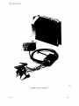
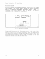
8500
MODULAR MDL SERIES
TRIGGER TRACE
ANALYZER
INSTALLATION
SERVICE
INSTRUCTION
MANUAL
Tektron~
COMMITTED TO EXCELLENCE
WARNING
THE FOLLOWING SERVICING INSTRUCTIONS
ARE FOR USE BY QUALIFIED PERSONNEL ONLY.
TO AVOID PERSONAL INJURY, DO NOT
PERFORM ANY SERVICING OTHER THAN THAT
CONTAINED IN OPERATING INSTRUCTIONS
UNLESS YOU ARE QUALIFIED TO DO SO.
PLEASE CHECK FOR CHANGE INFORMATION
AT THE REAR OF THIS MANUAL.
This manual supports the following
TEKTRONIX products:
8550
Option
8540
Option
Products
03
03
8550F03
8540F03
8500
MODULAR MOL SERIES
TRIGGER TRACE
ANALYZER
INSTALLATION
SERVICE
Tektronix, Inc.
P.O. Box 500
Beaverton, Oregon
070-3761-00
Product Group 61
97077
Serial Number _ _ _ _ _ __
First Printing OCT 1981
Revised JAN 1983
Co pyright © 1981 by Tektronix, Inc. All rights reserved.
Contents of this publication may not be reproduced in any
form without the permission of Tektronix, Inc.
Products of Tektronix, Inc. and its subsidiaries are
covered by U.S. and foreign patents and/or pending patents.
TEKTRONIX, TEK, SCOPE-MOBILE, and ~ are registered
trademarks of Tektronix, Inc. TELEQUIPMENT is a registered
trademark of Tektronix D .K. Limited.
There is no implied warranty of fi tness for
purpose. Tektronix, Inc. is not liable for
damages.
a particular
consequential
Specification and price
are
change
privileges
Printed in U.S.A.
reserved.
TTA Installation
PREFACE
ABOUT THIS MANUAL
This manual contains information on how to install the Trigger Trace Analyzer
in a compatible TEKTRONIX microcomputer development system.
~
The Trigger Trace Analyzer should only be installed by a Tektronix
Field Service Specialist.
Tektronix, Inc., is not obligated to
furnish service to repair damage resulting from attempts by
unauthorized personnel to install this product. Please call your
nearest Tektronix Field Service Office for installation.
MANUAL ORGANIZATION
This manual is divided into four sections:
Section
contains an overview of the Trigger Trace Analyzer.
Section 2 contains instructions
jumpers and straps.
for
configuring
Trigger
Trace
Analyzer
Section 3 provides instructions for installing the Trigger Trace Analyzer.
Section 4 discusses verification of the installed Trigger Trace Analyzer.
NOTE
In this manual, the terms "development system" , "mainframe" , and
"microcomputer development system" apply equally to the 8550
Microcomputer Development Lab and to the 8540 Integration Unit.
CHANGE INFORMATION
Change notices are issued by Tektronix, Inc., to document changes to the
manual after it has been published. Change information is located at the
back of this manual, following the yellow tab marked "CHANGE INFORMATION &
TEST EQUIPMENT".
When you receive the manual, you should enter any change
information into the body of the manual, according to instructions on the
change notice.
@
i
Preface - TTA Installation
REVISION HISTORY
As this manual .is rev ised and
reprinted,
reVlSlon
his tOl~Y
information
lS
included on the text and diagram pages. Original manual pages are identified
with an '@' symbol at the bottom inside corner of the page.
When existing
pages are revised, the '@' symbol is replaced with a revision code and date
(REV A OCT 1981). New pages added to a section, whether they contain old,
new, or revised information, will be identified with the '@' symbol and a
date (@ OCT 1981).
DOCUMENTATION OVERVIEW
The support documentation for TEKTRONIX microprocessor development systems
consists of three groups of manuals: user's manuals, service manuals, and
installation manuals.
Users manuals contain information required to operate the system and its
peripheral devices.
Users manuals are identified by their grey covers and
are provided as standard accessories with the system package.
Installation manuals provide information required to install and verify the
operation of system components. Installation manuals have blue covers and
are provided as standard accessories with the system package.
Service manuals provide information required to test, troubleshoot and repair
a system and its peripheral devices. Service manuals are identified by their
blue covers and may be purchased as optional accessories.
ii
@
TTA Installation
CONTENTS
Page
Safety Summary ••••••••••••.••••••.••••••••••••..•••••••••••••• v
SECTION 1 GENERAL INFORMATION
I n trod u c t i on ••••••••••••••••••••••••••••.•••••••••••••••••••
Product Description •••••••••••••••••••••••••••••••••••••••••
TTA Circuit Board #1 •••••••••••••••••••••..•••••••••••••••
TTA Circuit Board #2 ••••••••••••••••••••••••••••••••••••.•
TTA Interconnect Cables •••••••••••••••••••••••••••••••••••
Data Acquisi tion Interface •••••••••••••••.••••••••••••••••
Data Acquisition Probe ••••••••••••••••••••••••••••••••••••
Specifications ••••••••••••.•••••••••••••••••••••.••••.••••••
1-1
1-1
1-2
1-3
1-4
1-5
1-6
1-7
SECTION 2 JUMPER CONFIGURATIONS
. . .. . . .... . . . . . . . . . . .. . . .. . .. .. . . . . . . . . .
2-1
TTA Circuit Board #1
TTA Circui t Board #2 •••••••••••••••••••••••••••••••••••••••• 2-1
SECTION 3 INSTALLATION PROCEDURES
In trod u c t ion •••••••••••••••••••••••••••••••••••••••••••.••••
Preparing the Development System ••••••••••••..••.•••••••••
Installing TTA Circuit Board #1 ••••••••••••••••••..•••••••
Installing TTA Circuit Board #2 •••••••••••••••••••••••••••
Installing TTA Interconnect Cables ••••••••..••••••••••••••
Installing the Data Acquisition Interface •••••••••.•••••••
Reassembling the Development System •••••••••••••••••••••••
Installing the Data Acquisition Probe ••.••••••.•••••.•••••
Installing Trigger Trace Analyzer Option Firmware •••••••••
3 -1
3-1
3-2
3-3
3-4
3-4
3-5
3-6
3-6
SECTION 4 PERFORMANCE VERIFICATION
Introduction •.•.••.••••.••••••••••.••••.••••••••••
4-1
TTA/8550 Performance Verification •.••••••••••••••••••••.•••• 4-1
TTA/8540 Performance Verification ••••••••••••••••••••••••••• 4-1
It
REV JAN 1983
............
iii
Contents - TTA Installation
ILLUSTRATIONS
Fig.
1-1
1-2
1-3
1-4
1-5
2-1
2-2
2-3
3-1
3-2
3-3
3-4
TTA Circuit Board #1 ••.•••••..•...•......••.•.•...•..••.
TTA Circuit Board #2 .•.......••••..• eeeee~a • • • • • • • • • o • • •
TTA Interconnect Cables ....•.•.••.....••...•.••.••..••..
Data Acquisition Interface ..•...•.•.•.•••..••••.••••.•..
P6451 Data Acquisition Probe .•.•..•..•......••....••••..
Jumper locations, TTA Circuit Board #2 •..•..••.•.•.•.•.•
TTA counter clock selection: J6165 ..••..•.••...••..••..
OPREQ/SLVOPREQ selection: JI031 ...•.••••..•••••..••...•
Removing/installing the mainframe top cover •.......••..•
Recommended circuit board arrangement ••..•..••••.••...•.
Installing the Data Acquisition Interface ...••••.••••.•.
System ROM Board socket locations ...••...•...•..•....•..
Page
1-2
1-3
1-4
1-5
1-6
2-1
2-2
2-2
3-2
3-3
3-5
3-6
TABLES
Table
No.
Page
1-1 Environmental Characteristics • . . . . . . . . . . . . . . . . . . . . . . . . . . 1-7
1-2 Electrical Characteristics ~~~~~ . . . . . . . . . . . . . . . . . . . . . . • . . 1-7
iv
REV JAN 1983
TTA Installation
OPERATORS SAFETY SUMMARY
The general safety information in this part of the summary is for both
operating and servlclng personnel. Specific warnings and cautions will be
found throughout the manual where they apply, but may not appear in this
summary.
TERMS IN THIS MANUAL
CAUTION statements identify conditions or practices
damage to the equipment or other property.
that
could
result
in
WARNING statements identify conditions or
personal injury or loss of life.
that
could
result
in
practices
TERMS AS MARKED ON EQUIPMENT
CAUTION indicates a personal lnJury hazard not immediately accessible as one
reads the marking, or a hazard to property including the equipment itself.
DANGER indicates a personal injury hazard immediately accessible as one reads
the marking.
SYMBOLS AS MARKED ON EQUIPMENT
@
~
DANGER high voltage.
~~
Protective ground (earth) terminal.
~
ATTENTION - Refer to manual.
V
Safety Summary - TTA Installation
SAFETY PRECAlJTIONS
Growlding the Product
This product is grounded through grounding conductors in the interconnecting
cables.
To avoid electrical shock, plug the supporting system's power cord
into a properly wired receptacle. A protective ground connection by way of
the grounding conductor in the power cord is essential for safe operation.
Use the Proper Power Cord
Use only the power cord and connector specified for your product.
Use only a power cord that is in good condition.
Refer cord and connector changes to qualified service personnel.
Use the Proper Fuse
To avoid fire hazard, use only the fuse specified in the parts list for your
product.
Be sure the fuse is identical in type, voltage rating, and current
rating.
Refer fuse replacement to qualified service personnel.
Do Not Operate in Explosive Atmospheres
To avoid explosion, do not operate this product in an atmosphere of explosive
gases ~~less it has been specifically certified for such operation.
Do Not Remove Covers or Panels
To avoid personal injury, do not remove the product covers or panels.
operate the product without the covers and panels properly installed.
vi
Do not
@
Safety Summary - TTA Installation
SERVICING SAFETY SUMMARY
FOR QUALIFIED SERVICE PERSONNEL ONLY
(Refer also to the preceding Operators Safety Summary)
Do Not Service Alone
Do not perform internal service or adjustment of this product unless
person capable of rendering first aid and resuscitation is present.
another
Use Care When Servicing With Power On
Dangerous voltages exist at several points in this product.
To avoid
personal injury, do not touch exposed connections and components while power
is on.
Disconnect power before removing protective panels, soldering,
components.
or
replacing
Power Source
This product is intended to operate from a power source that will not apply
more than 250 volts rms between the supply conductors or between either
supply conductor and ground. A protective ground connection by way of the
grounding conductor in the power cord is essential for safe operation.
@
vii
TTA Installation
3761-8
Trigger Trace Analyzer
viii
@
TTA Installation
Section 1
GENERAL INFORMATION
INTRODUCTION
The Trigger Trace Analyzer (TTA) is an accessory to TEKTRONIX 8500-series
microcomputer development systems.
The TTA provides a set of real-time
hardware and software debugging tools.
This manual contains procedures for installing
8500-series
microcomputer development system
following sections:
the
and
TTA in a compatible
is divided into the
contains general information about the TTA.
•
Section
•
Section 2 contains information about TTA jumpers and switches.
•
Section 3 contains
development system.
•
Section 4 contains information about TTA performance verification.
details
about
installing
the
TTA
in
your
For information about operating the TTA, refer to your System Users Manual
and to the Trigger Trace Analyzer Users Manual. Service information is
provided in the optional Trigger Trace Analyzer Service Manual.
PRODUCT DESCRIPTION
The Trigger Trace Analyzer has six standard subassemblies. Each subassembly
is described briefly in this section. These six standard subassemblies are:
•
•
•
•
•
@
TTA Circuit Board #1
TTA Circuit Board #2
Two TTA Interconnect Cables
Data Acquisition Interface
Data Acquisition Probe
1 -1
General Information - TTA Installation
TTA CIRCUIT BOARD #1
TTA Circuit Board #i contains memory and control circuitry for the Trigger
Trace Analyzer =
This circuit board is inserted into the Main Interconnect
Figure
1-1
Board of a compatible microcomputer development system.
illustrates
TTA Circuit Board #1.
Refer to Section 3 for specific
information on how to install this circuit board.
o
o
Two 50-pin
Side Connectors
[~-----------_/~ ~----~~ ~ ~~--!
In
100-pin Bottom
Edge Connector
1IIIIIIIIIIIIIIIIIIIlllllIlllllllllIlIllnL-_ _ _--'
I
376,,1
Fig. 1-1. TTA Circuit Board #1.
During normal TTA operation, the 100-pin edge connector at the bottom of this
board is inserted into the main interconnect board of a microcomputer
development system. The two 50-pin edge connectors at the top of this board
are connected to TTA Circuit Board #2 via the TTA Interconnect Cables. The
26-pin edge connector at the top of the board is connected to the Data
Acquisition Interface with a 26-line ribbon cable.
1-2
@
General Information - TTA Installation
TTA CIRCUIT BOARD #2
TTA Circuit Board #2 contains memory and control circuitry for the Trigger
Trace Analyzer.
This circuit board is inserted into the Main Interconnect
Board of your microcomputer development system. Figure 1-2 illustrates TTA
Circuit Board #2.
Refer to Section 3 for specific information on how to
install this circuit board.
o
o
o
100-pin Bottom
Edge Connector
(3762-5)3761-2
Fig. 1-2. TTA Circuit Board #2.
During normal TTA operation, the 100-pin edge connector at the bottom of this
board is inserted into the Main Interconnect Board of a microcomputer
development system. The two 50-pin edge connectors at the top of this board
are connected to TTA Circuit Board #1 via the TTA Interconnect Cables.
@
1 -3
General Information - TTA Installation
TTA INTERCONNECT CABLES
The two TTA interconnect cables form an electrical connection between the two
TTA circuit
Each cable connects a 50=pin edge connector on one TTA
board to a 50-pin edge connector on the other TTA board.
Figure 1-3
illustrates the TTA Interconnect Cables. Refer to Section 3 for specific
information on how to install the TTA Interconnect Cables.
Fig. 1-3. TTA Interconnect Cables.
The 50-pin connectors on these cables accept the 50-pin
of the two TTA circuit boards.
1-4
top-edge
connectors
@
General Information - TTA Installation
DATA ACQUISITION INTERFACE
The Data Acquisition Interface consists of an interface circuit board, a
control panel, and a 26-line ribbon cable. The interface circuit board
interfaces signals external to the TTA (and to the microcomputer development
system) with the rest of the TTA circuitry. The control panel provides the
physical connections and controls for these external signals.
The 26-line
ribbon cable carries the interfaced signals between the Data Acquisition
Interface and TTA Circuit Board #1.
Figure 1-4 illustrates the Data
Acquisition Interface. Refer to Section 3 for specific information on how to
install the Data Acquisi tion Interface.
25-pin
Connector
(2785-62)3761-4
Fig. 1-4. Data Acquisition Interface.
The Data Acquisition Interfaced is installed within the rear panel of your
development system. The 26-pin ribbon cable attaches to a top edge connector
on TTA Circuit Board #1.
1-5
General Information - TTA Installation
DATA ACQUISITION PROBE
The Data Acquisition PLobe uSed by the TTA lS a TEKTRONIX r6451 Data
Acquisition Probe. This probe allows the TTA to acquire up to nine external
signals, including a clock signal.
Figure 1-5 illustrates a P6451 Data
Acquisition Probe (probe leads are not shown).
Refer to Section 3 for
specific information on how to install the Data Acquisition Probe.
3761-5
Fig. 1-5. P6451 Data Acquisition Probe.
The 25-pin connector on this probe must be installed in the 25-pin socket
the control panel of the Data Acquisition Interface.
1-6
on
@
General Information - TTA Installation
SPECIFICATIONS
Table 1-1
Environmental Characteristics
Characteristic
Description
=======================================================
Temperature
Operating
Storage
OCto +50 C (+32 F to +122 F)
-55 C to +75 C (-67 F to +167 F)
Humidity
To 90% relative non-condensing
Altitude
Operating
Storage
To 4 500 m (15,000 feet)
To 15 000 m (50,000 feet)
Table 1-2
Electrical Characteristics
Characteristic
Requirement
: Supplemental Information
========================================================================
Voltage
: +5.2 Vdc (+1-)5%
Current
: 6.966 A @ 5.2 Vdc : With Data Acquisition Interface
: 6.900 A @ 5.2 Vdc : No Data Acquisition Interface
Power Dissipation: 3.6 Watts (approx): With Data Acquisition Interface
: 3.5 Watts (approx): No Data Acquisition Interface
1~
TTA Installation
Section 2
JUMPER CONFIGURATIONS
TTA CIRCUIT BOARD #1
There are no jumpers, straps, or switches on TTA Circuit Board #1.
TTA CIRCUIT BOARD #2
TTA Circuit Board #2 has two jumper locations, a switch, an LED, and a row of
testpoints. Figure 2-1 illustrates the positions of the jumper locations and
testpoint on TTA Circuit Board #2.
Refer to Fig. 2-1 as you read the
following descriptions.
o
~~
'-y---J ~
J1031 J1041
50-pin
Edge Connector
50-pin
Edge Connector
o
o
100-pin Bottom
Edge Connector
J6165
3762-5
Fig. 2-1. Jumper locations, TTA Circuit Board #2.
@
2-1
Jumper Configurations - TTA Installation
This jumper position selects a clock signal for the TTA's counter.
Figure 2-2 shows how this jumper can be configured. During normal
operation, this jumper should sele~t the i MHz signal.
J6165
o
o
o
o
o
o
Selects
10 MHz
Selects
5 MHz
(normal operation)
Selects
1 MHz
3762-6
Fig. 2-2. TTA counter clock selection: J6165.
This jumper position selects either the SLVOPREQ(L) signal or the
OPREQ(L) signal for TTA/system timing. Figure 2-3 shows how this
jumper can be configured.
During normal operation, this jumper
should select the SLVOPREQ(L) signal.
J1031
2
3
4
5
2
6
3
4
5
6
o
o
Selects OPREO
Selects SLVOPREO
(Normal Operation)
3762-7
Fig. 2-3. OPREQ/SLVOPREQ selection: J1031.
J1041
This testpoint provides access to
RUN(H), CMEM(L), and logic ground.
four
TTA
signals:
MSTRUN(H) ,
SW1051
This momentary-contact switch supports TTA diagnostics for
testing. The switch is not used during normal TTA operation.
board
NOTE
The LED at the top of TTA board #2 is enabled by the ON(H)
This LED, like the test switch, is for servicing only.
2-2
signal.
@
TTA Installation
Section 3
INSTALLATION PROCEDURES
INTRODUCTION
This section contains the procedures for installing the Trigger
Trace Analyzer in your development system. The following
procedures are included:
1.
Preparing the development system
2.
Installing TTA Circuit Board #1
3.
Installing TTA Circuit Board #2
4.
Installing the TTA Interconnect Cables
5.
Installing the Data Acquisition Interface
6.
Reassembling the development system
7.
Installing the Data Acquisition Probe
8.
Installing Trigger Trace Analyzer Option Firmware
PREPARING THE DEVELOPMENT SYSTEM
I
WARNING
I
Verify that the primary power to the microcomputer
development system is OFF.
REV JAN 1983
1.
Remove the cover retainers at the upper corners on
the rear of the mainframe.
See Fig. 3-1.
2.
Remove the top cover by sliding it straight back,
then set it aside.
3-1
Installation Procedures - TTA Installation
r
Retainer
Screws
(3665-6)3761-6
Fig. 3-1. Removing/installing the mainframe top cover.
INSTALLING TTA CIRCUIT BOARD #1
3-2
1.
Facing the front of the mainframe, hold TTA Circuit Board #1 by
its upper edges and align it with other circuit boards in the
mainframe, with the component side facing left.
2.
Guide the circuit board down the vertical channels at position
J13 of the microcomputer development system's Main Interconnect
Board. See Fig. 3-2.
3.
When the circuit board reaches the connector on the Main
Interconnect Board, press down firmly and evenly on the top edge
of the circuit board until it snaps into place.
@
Installation Procedures - TTA Installation
INSTALLING TTA CIRCUIT BOARD #2
1.
Facing the front of the mainframe, hold TTA Circuit Board #2 by
its upper edges and align it with other circuit boards in the
mainframe, with the component side facing left.
2.
Guide the circuit board down the vertical channels at position
J12 of the development system's Main Interconnect Board.
See
Fig. 3-2.
3.
When the circuit board reaches the connector on the Main
Interconnect Board, press down firmly and evenly on the top edge
of the circuit board until it snaps into place.
N
0
~
~
.!!
]
c
0
~
~
u
E
II)
III
III
1ii
CIl
0.
0.
>
CIl
>
(5
(5
gc
II)
II)
II)
()
E 0 Q:0
II)
u
:! g CDC)
III
E
III
::l
CD
1ii
>
CIl
"it
"5
C)
c
E
W
III
..J
II)
cg
5
6
>
(5
~
E
CD
:!
E
III
0
0
~
Q:
~
~
III
m
CIl
Q)
8
9
.., .., .., .., .., ".., .., ..,
1
2
3
0
'5
~
« «
0.
N
III
..,...
10
11 12 13
14
15
CIl
I
C")
0
.....,
..,...
0.
CD
()
:;
E
~
~
CIl
"it
CIl
0
0.
Q:
III
()
Q:
g
III
:;
E
........, .....,~ .....,~
0.
<XI
~
(5
II)
II)
CD
0
....
U U
(5
II)
II)
......,
III
C')
LSYSTEM~
SECTION
m
~
CIl
N
7
"EIII
'5
.,....
4
"EIII
....
~
0
2
0
0
E
:!
E
III
II)
...
2
w
LD
PROGRAM
SECTION
Q:
g
III
W
cg
I
16 \
I
Front Panel
3762-13
Fig. 3-2. Recommended circuit board arrangement.
@
3-3
Installation Procedures - TTA Installation
INSTALLING THE TTA INTERCONNECT CABLES
1.
Facing the front of the mainframe, grasp one of the TTA
Interconnect Cables.
Align the socket at one end of the cable
with the nearer edge connector at the top of TTA Circuit Board
#2 (installed in slot J12). Align the socket at the other end
of this same interconnect cable with the nearer edge connector
on top of TTA Circuit Board #1 (installed in slot J13). The
openings of the sockets must be facing downward, with the ribbon
cable running between the two TTA Circuit Boards.
2.
Press down evenly and firmly on one
snaps into place.
3.
Press down evenly and firmly on the other socket until it
into place.
4.
Repeat this procedure to install the other TTA Interconnnect
Cable across the 50-pin edge connectors remaining on each
circuit board and towards the rear of the development system's
mainframe.
of
the
sockets
until
it
snaps
INSTALLING THE DATA ACQUISITION INTERFACE
1.
Now, face the rear panel of the mainframe. Notice a blank plate
near the upper left corner of the rear panel. Remove the four
screws securing this plate to the mainframe, then remove the
plate. Set the screws and the plate aside.
2.
Mount the Data Acquisition Interface in the rear panel of the
mainframe, as shown in Fig. 3-3. Use the screws removed in step
1•
3.
3-4
Connect the 26-pin socket at the end of the Data Acquisition
Interface's ribbon cable to the 26-pin top edge connector of TTA
~lrCU1~ Board #i.
Be certain that pin 1 of the edge connector
is aligned with pin 1 of the socket.
@
Installation Procedures - TTA Installation
Mounting
Screws
\
Rear Panel of Mainframe
(8300 Series)
3762-14
Fig. 3-3. Installing the Data Acquisition Interface.
REASSEMBLING THE DEVELOPMENT SYSTEM
@
1.
Refer back to Fig. 3-1. Slide the top cover back into the guide
tracks at the top of the mainframe. Be certain that the cover
is properly seated in the slot at the front of the mainframe.
2.
Place the cover retainers at the upper left and right corners on
the rear of the mainframe.
3.
Thread the four screws through the cover retainers into tbe
mainframe, and tighten these screws securely.
3-5
Installation Procedures - TTA Installation
INSTALLING THE DATA ACQUISITION PROBE
Insert the 25-pin connector at the end of the Data Acquisition Probe's cable
into the 25=pin socket in the Data Acquisition Interface's control panel.
INSTALLING TRIGGER TRACE ANALYZER OPTION FIRMWARE
When the Trigger Trace Analyzer (TTA) option is shipped for installation into
an 8540 rather than an 8550, the option package includes control/diagnostic
firmware for the 8540. The firmware is in the form of three ROM devices, to
be installed on the 8540 System ROM board. (The same firmware is available
also from Tektronix in an 8550-to-8540 conversion kit (Tektronix part No.
020-0795-0X) that converts your 8550 TTA option for 8540 operation.)
Typically, your 8540 System ROM board contains the basic system firmware,
consisting of the 8540 operating system and diagnostic procedures. In
addition, the board may also contain some option control/diagnostic firmware.
Although there is no electrical reason to install a particular ROM into a
particular socket location (any ROM operates in any socket), Tektronix has
assigned permanent socket locations to the operating system, diagnostic, and
option firmware. Sockets CS95 -- CS9F contain the 8540 operating system, and
sockets CS92 -- CS94 contain the 8540 diagnostics. The remaining sockets are
available to accept option firmware. This arrangement is shown in
Install your TTA Option into locations CS8C, CS8D, and CS8E, or any other
available sockets within the reserved 8540 option locations.
NOTE
The number of available option sockets is limited.
If you don't
have enough room to install firmware for a particular option,
t"emove unused option r ir~mwat·e.
ROM Socket Strapping
Since all presently available 8540 option firmware is stored in 2764 devices,
the strapping associated with each socket needs no changing.
3-6
REV JAN 1983
Installation Procedures - TTA Installation
DDDDD
0000
0000
00000
0000
0000
00000
0000
0000
00000
0000
0000
00000
J1111
1'eJDOIAGNOSTICS
0000
0000
00000
OOOOOD
0000
0000
00000
°DS:C
0000
0000
00000
0
cs:o
0000
0000
00000
0000
0000
00000
°DS:E °DSSOF
0000
0000
00000
0
0
8540
OPTIONS
0000
0000
0000
0000
0000
0000
0000
0000
00000
00000
00000
00000
00000000
3921-17A
Fig. 3-4.
ADD JAN 1983
System ROM board socket locations.
3-7
TTA Installation
Section 4
PERFORMANCE VERIFICATION
INTRODUCTION
This section describes the procedures to verify that the Trigger Trace
Analyzer operates properly in conjunction with your development system.
TTA/8550 PERFORMANCE VERIFICATION
With the 8550 Microcomputer Development Lab, the performance of the TTA is
verified by running the 8550 system's disc-based diagnostics. That is, when
the system diagnostics for the 8550 Microcomputer Development Lab are
executed in the "RUN ALL" mode, the TTA is detected and tested. Refer to the
Verification section of the 8550 Microcomputer Development Lab Installation
Guide for the procedure to execute these system diagnostics. If an error
message indicates that the TTA failed system diagnostics~ contact authorized
repair personnel.
TTA/8540 PERFORMANCE VERIFICATION
With the 8540 Integration Unit, the performance of the TTA is verified by
running the 8540 system's ROM-based diagnostics. That is, when the system
diagnostics for the 8540 Integration Unit are executed in the "RUN ALL" mode,
the TTA is detected and tested. Refer to the Verification section of the
8540 Integration Unit Installation Guide for the procedure to execute these
system diagnostics. If an error message indicates that the TTA failed system
diagnostics, contact authorized repair personnel.
@
4-1