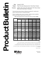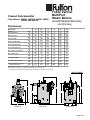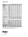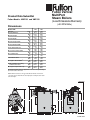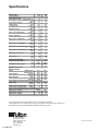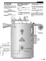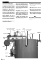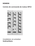
1
Installation Operation And
Maintenance Manual
December 2011UHY-DQXDU\
Serial # : ___________________________
Model # : ___________________________
Fulton Order # : ___________________________
Sold To : ___________________________
Job Name : ___________________________
Date : ___________________________
Fulton VMP
(Vertical Multi-Port)
Gas Fired Steam Boilers
40-150 HP
ProductBulletin
Date:
January 22, 2010
Subject:
Water Chemistry Requirements for Fulton Steam Products
Products:
ICS/ICX, FB-A, FB-F, FB-S, VMP, PVLP, PHP, Electric Steam
Boilers and Unfired Steam Generators
Please note that the water chemistry is different for carbon steel vs. stainless steel
pressure vessels and vertical vs. horizontal orientation.
Effective immediately, please use the limits below. Should you have any questions,
please do not hesitate to contact Fulton at 315-298-5121.
Water Chemistry Requirements for Fulton Steam Products (to 300 psig MAWP)
Carbon Steel
Feedwater
Parameter
Stainless Steel
Vertical
Horizontal
Boiler/Steam Boiler/Steam
Pac Water
Pac Water
Feedwater
Vertical
Horizontal
Boiler/Steam Boiler/Steam
Pac Water
Pac Water
pH
7.5-9.5
8.5-10.5
8.5-10.5
6.0-9.5
8.5-10.5
8.5-10.5
Feedwater
Temperature
140F*
---
---
140F*
---
---
Hardness as
CaCO3
<2ppm
<10 ppm
<15 ppm
<2 ppm
<10 ppm
<15 ppm
Chlorides
---
---
---
---
50 ppm
50 ppm
Total
Alkalinity
Total
Dissolved
Solids
Suspended
Solids
Total Organic
Carbon
Iron
---
<300 ppm
<500 ppm
---
<300 ppm
<500 ppm
---
<2000 ppm
<3000 ppm
---
<2000 ppm
<3000 ppm
No visual
turbidity**
No sheen
No foam+
Colorless
liquid++
No visual
turbidity**
No sheen
No foam+
Colorless
liquid++
No visual
turbidity**
No sheen
No foam+
Colorless
liquid++
No visual
turbidity**
No sheen
No foam+
Colorless
liquid++
No visual
turbidity**
No sheen
No foam+
Colorless
liquid++
No visual
turbidity**
No sheen
No foam+
Colorless
liquid++
<1ppm*
ND
ND
<5ppm
ND
ND
ND
ND
ND
ND
ND
ND
---
<2985
<4477
---
<2985
<4477
Dissolved
Oxygen
Visual Oil
Conducivity
(uS/cm)
NOTES:
*This is a minimum temperature. Feedwater temperatures below 200F will require an oxygen scavenger.
** Suspended solids: Take a water sample. After the sample sits for 10 minutes, no solids should be visible.
+ Total Organic Carbon: Take a water sample. Shake vigorously for 30 seconds. No sheen or foam should be visible.
++ Iron: Take a water sample. Hold the sample against a white background. The water should have no visible yellow, red or
orange tinge.
ND: None Detected.
The Fulton Companies
972 Centerville Road
Pulaski, N.Y. 13142
Product Bulletin
2010-001PB
Contents
Section
1
2
3
4
5
Safety Warnings
and Precautions
PAGE 3
Installation
PAGE 9
Operation
PAGE 17
Maintenance
PAGE 31
Parts and
Warranty
PAGE 35
VMP IOM
1
2 VMP IOM
Section
1
2
3
4
5
Safety Warnings
and Precautions
VMP IOM
3
4 VMP IOM
Safety Warnings and Precautions
This manual is provided as a guide to the correct operation and
maintenance of your Fulton Gas Fired Steam Boiler, and should be
permanently available to the staff responsible for the operation of
the gas fired boiler.
These instructions must not be considered as a complete code of
practice, nor should they replace existing codes or standards which
may be applicable.
The requirements and instructions contained in this section
generally relate to the standard Fulton Gas Fired Steam Boiler.
When installing a packaged unit, this entire section should be read
to ensure that the installation work is carried out correctly.
Prior to shipment the following tests are made to assure the
customer the highest standards of manufacturing:
a)
b)
c)
d)
e)
f)
g)
h)
Material inspections.
Manufacturing process inspections.
ASME welding inspections.
ASME hydrostatic test inspection.
Electrical components inspection.
Operating test.
Final Engineering Inspection
Crating inspection.
All units are crated for fork lift transport. Once uncrated, all units can
be transported with a forklift. Under no circumstances should weight
be allowed to bear on the jacket, control panel, or fan housing of any
Fulton Boiler.
The customer should examine the boiler for any damage, especially
the refractories. It is the responsibility of the installer to ensure
all parts supplied with the boiler are fitted in a correct and safe
manner.
NOTE
The installation of the Fulton Gas Fired Steam Boiler should
be carried out by competent personnel in accordance with the
standards of the National Fire Protection Association, National
or Canadian Electrical Code. All state and jurisdictional codes
beyond the scope of the applicable ASME Boiler and Pressure
Vessel Codes, for its corresponding classification, should be
followed in all cases. Jurisdictional authorities must be
consulted prior to installation.
WARNING
Operating the boiler beyond its design limits can damage the
boiler and can also be dangerous. Do not operate the boiler
outside its limits. Do not try to upgrade the boiler performance
by unapproved modifications. Unapproved modifications can
cause injury and damage. Contact your Fulton dealer before
modifying the boiler.
WARNING
A defective boiler can injure you or others. Do not operate a
boiler which is defective or has missing parts. Make sure that
all maintenance procedures are completed before using the
boiler. Do not attempt repairs or any other maintenance work
you do not understand. Obtain a Service Manual from Fulton
or call a Fulton Service Engineer.
Rigging your boiler into position should be handled by a competent
rigger experienced in handling heavy equipment.
WARNING: If the information in this manual is not followed exactly, a fire or
explosion may result causing property damage, personal injury or loss of life.
- Do not store or use gasoline or other flammable vapors and liquids in the vicinity of
this or any other appliances.
- WHAT TO DO IF YOU SMELL GAS
• Do not try to light any appliance.
• Do not touch any electrical switch; do not use any phone in your building.
• Immediately call your gas supplier from a neighbor’s phone. Follow the gas
supplier’s instructions.
• If you cannot reach your gas supplier, call the fire department.
- Installation and service must be performed by a qualified installer, service agency
or the gas supplier.
VMP IOM
5
Safety Warnings and Precautions
For Your Safety
The following WARNINGS, CAUTIONS, and NOTES appear in various sections of this manual.
They are repeated on these safety summary pages as an example and for emphasis.
WARNINGS must be observed to prevent serious injury, or death to personnel.
CAUTIONS must be observed to prevent damage or destruction of equipment or loss of operating effectiveness.
NOTES must be observed for essential and effective operating procedures, conditions, and as a statement to be highlighted.
It is the responsibility and duty of all personnel involved in the operating and maintenance of this equipment to fully understand the
WARNINGS, CAUTIONS, and NOTES by which hazards are to be eliminated or reduced. Personnel must become familiar with all
aspects of safety and equipment prior to operation or maintenance of the equipment.
WARNING
NOTE
Care should be taken to ensure that the blow off receptacle
used meets the regulations covering such vessels. A means to
cool boiler blowdown water to <140o F prior to discharging to
floor drains is required for personnel and equipment
protection.
After installation is complete and prior to operation the
pressure vessel should be cleaned or boiled out per
instructions included in this manual.
WARNING
Only properly trained personnel should install and maintain
water gauge glass and connections. Wear safety glasses
during installation. Before installing, make sure all parts are
free of chips and debris. Gauge glass valves must be fully
open to prevent boiler water damage if a gauge glass breaks.
WARNING
Prior to the commencement of any work requiring the removal
of cover plates and the opening of the control panel box, the
electrical supply to the boiler must be disconnected.
WARNING
DO NOT TAMPER WITH THE SAFETY FEATURES OF THE
LOW WATER SAFETY CUT OFF.
NOTE
a) The fused disconnect switch that controls the feed water
pump should be kept in the “on” position at all times during
the boiler operation as well as during the non-operating
period of the boiler.
b) This switch should be turned “off” only when repairs or
adjustments should be made.
NOTE
The feedwater pump will continue to operate until the water
reaches the correct level in the boiler. This level is
approximately the center of the water gauge glass.
NOTE
To ensure that your Fulton Steam Boiler is kept operating
safely and efficiently, follow the maintenance procedures set
forth in Section 4 of this manual.
WARNING
When shutting down the boiler for any extensive repairs, shut
off main disconnect switches on both the boiler and the feed
water pump.
NOTE
If only the top refractory is to be changed, the bottom
refractory need not be removed.
WARNING
Do not clean the gauge glass while pressurized. Ensure gauge
glass valves are fully shut prior to glass removal.
WARNING
Do not allow anyone to operate, service or repair this
equipment unless they fully understand all applicable sections
of this manual.
CAUTION
To prevent corrosion fatigue at the feedwater nozzle or
cold end corrosion, boiler feed water must be at least
140o F prior to entry into the boiler.
CAUTION
A temperature exceeding 100oF in the boiler room may
cause premature failure of electrical components in the
boiler control panel.
CAUTION
The water chemistry in the boiler must be kept within
limits outlined in this manual. Failure to do so will likely
cause premature boiler pressure vessel failure and poor
steam quality.
6 VMP IOM
NOTE
The boiler blow off operation should be done once during the
day when the boiler is at 10 PSIG or less.
NOTE
After a new Fulton Boiler has been in operation for several
months, pieces of burned metal will be found in the space at
the bottom of the boiler. These pieces of metal are the remains
of a light gauge metal form which was used during
manufacture for forming the boiler insulation. This is a normal
condition and does not affect the efficiency or the life of the
boiler in any way.
Safety Warnings and Precautions
VMP IOM
7
8 VMP IOM
Section
1
2
3
4
5
Installation
VMP IOM
9
Installation
Gas Train Assembly
Transformer
Burner Plate Assembly
Top Plate Assembly
Secondary Air Damper
Scroll
Burner Motor
Flue Cover Plate
Lifting Hook(s)
Stainless Steel Ring
To
O.P.C.*
Steam Gauge
Assembly
Gauge Glass
Valve
To
H.P.C.*
Gauge Glass and
Protector Rods
Flue Outlet
Gauge Glass
Valve
Water Column
Top Refractory
Turbulator
Control Box
Fiberglas Insulation
Bottom Refractory
Outside Jacket
Feedwater Inlet
Blowdown Outlet
Handhole
Blowdown Outlet
Castable Refractory Insulation
Clean Out Opening
* O.P.C. = Operating Pressure Control
* H.P.C. = High Pressure Control
10 VMP IOM
Product Data Submittal
Fulton Models: VMP40, VMP49.5, VMP50, VMP60,
VMP80, VMP100, VMP130 and
VMP150
Dimensions
Models VMP
Unit Size:
A. Boiler Diameter
40
40
50.5
1283
84
2133
90
2286
107
2718
56
1422
12
305
79
2006
35
889
17
432
73
1854
110
2794
BHP
IN
MM
IN
MM
IN
MM
IN
MM
IN
MM
IN
MM
IN
MM
IN
MM
IN
MM
IN
MM
IN
MM
B. Boiler Height
C. Boiler Depth
D. Boiler Height w/trim
E. Overall Boiler Width
F. Flue Outlet Diameter
G. To Center of Flue Outlet
H. Feedwater Inlet
J. Blowdown Outlet
K. Height to Steam Outlet1
L. Min. Clearance to Ceiling
49.5
49.5
55
1397
91
2312
100
2540
112
2832
62
1575
12
305
86
2184
35
889
18
457
77
4956
115
2921
50
50
55
1397
91
2312
100
2540
112
2832
62
1575
12
305
86
2184
35
889
18
457
77
4956
115
2921
Fulton Vertical
MultiPort
Steam Boilers
(Standard Burners)
60
60
55
1397
97
2464
100
2540
118
2984
62
1575
12
305
92
2237
35
889
18
457
84
2134
125
3175
80
80
63
1600
100
2540
114
2896
124
3150
68
1727
14
356
95
2413
35
889
18
457
89
2260
130
3302
100
100
69
1753
100
2540
119
3022
126
3200
74
1880
14
356
95
2413
35
889
18
457
89
2260
132
3353
130
130
76.5
1943
115
2921
128
3251
135
3429
84.5
2146
14
356
107
2718
39
991
22
559
102
2591
145
3683
150
150
76.5
1943
115
2921
130
3302
141
3582
84.5
2146
16
407
107
2718
39
991
22
559
102
2591
145
3683
Specifications and Dimensions are approximate. We reserve the right to change specifications and/or dimensions.
NOTE: Minimum clearance is 24” to the side and back and 36” in front of unit.
1. The boiler may be fitted with a 90o elbow spool piece making the steam outlet connection higher.
F
Minimum Clearance
For Burner Removal
SteamOutlet
L
G
D
C
A
K
B
H
J
E
Top View
Side View
Front View
11 VMP IOM
Specifications
Models VMP
40
49.5
Unit Horsepower
40
49.5
Boiler Connections
Steam Outlet 15 PSI - 150# Flanged IN
4
4
MM
101
101
Steam Outlet 150 PSI
IN NPT
3
3
MM
76
76
Feedwater Inlet
IN NPT
1
1
MM
25
25
Blowdown Outlet (2)
IN NPT
1.5
1.5
MM
38
38
Water Column Blowdown
IN NPT
1
1
MM
25
25
Surface Blowdown
IN NPT
.75
.75
MM
19
19
Safety Valve 150 PSI Inlet
IN NPT
.75
1
MM
19
25
Safety Valve 150 PSIOutlet
IN NPT
1
1.25
MM
25
31
Safety Valve 15 PSI Inlet (2)
IN NPT
1.25
1.25
MM
31
31
Safety Valve 15 PSI Outlet
IN NPT
1.5
1.5
MM
38
38
Natural Gas Connection
IN
1.5
1.5
MM
38
38
Light Oil Connection
IN
.25
.25
MM
6
6
Burner Motor (Gas)
HP
1.5
1.5
KW
1.1
1.1
Burner Motor (Oil/Combo)
HP
2
2
KW
1.5
1.5
Approximate Weights
Shipping Weights (approx.)
LB
5775
6550
KG
2620
2972
Operating Weight (approx.)
LB
6720
8850
KG
3050
4015
**Ratings Sea Level to 3000 FT. (914 M)
Output
1000 BTU/HR
1340
1656
1000 KCAL/HR
338
417
Steam Output
LBS/HR
1380
1708
KG/HR
626
775
Water Content
GAL
172
274
LITERS
651
1038
Approximate Fuel Consumption at Rated Capacity+
1595
1972
Natural Gas
FT3/HR
M3/HR
45
56
638
788
LP Gas
FT3/HR
M3/HR
18
22
Light Oil
GPH
11.0
13.9
LPH
41.6
52.6
Gas Pressure Required
Standard Burners Min.
IN W.C.
7
7
Gas Pressure Required
Standard Gas Train Max.
IN W.C.
13
13
Electrical Requirements/Amps for Burner Motors
208V, 50/60 CY, 3 Phase (Gas/Oil)
6.6/7.5
6.6/7.5
230V, 50/60 CY, 3 Phase (Gas/Oil)
6.0/6.8
6.0/6.8
460V, 50/60 CY, 3 Phase (Gas/Oil)
3.0/3.4
3.0/3.4
50
50
60
60
80
80
100
100
130
130
150
150
4
101
3
76
1
25
1.5
38
1
25
.75
19
1
25
1.25
31
1.25
31
1.5
38
1.5
38
.25
6
1.5
1.1
2
1.5
4
101
3
76
1
25
1.5
38
1
25
.75
19
1
25
1.25
31
1.25
31
1.5
38
2
51
.25
6
1.5
1.1
2
1.5
6
152
3
76
1
25
1.5
38
1
25
.75
19
1.25
31
1.5
38
1.5
38
2
51
2
51
.25
6
3
2.2
3
2.2
6
152
3
76
1.25
31
2
51
1
25
.75
19
1.25
31
1.5
38
1.5
38
2
51
2
51
.25
6
3
2.2
3
2.2
*6
203
4
101
1.25
32
2
51
1
25
.75
19
1.5
38
2
51
2
51
2
51
2
51
.375
9.5
10
7.5
10
7.5
*6
203
4
1.25
32
2
51
1
25
.75
19
1.5
38
2
51
2
51
2
51
2
51
.375
9.5
10
7.5
10
7.5
6575
2980
8209
3720
7370
3340
9227
4190
8000
3630
11760
5330
9500
4310
14525
6590
12350
5600
20135
9130
12350
5600
20135
9130
1673
422
1725
783
242
916
2009
506
2070
939
270
1022
2678
675
2760
1252
383
1450
3347
843
3450
1565
518
1960
4353
1097
4485
2035
810
3066
5022
1266
5175
2348
810
3066
1992
56
797
23
14.0
53
2392
68
957
27
17.0
64.3
3188
90
1275
36
22.8
87
3985
113
1594
45
28.0
106
5200
147
2080
59
37.0
140
5978
169
2391
68
42.0
159
7
7
9
9
40
40
13
13
27
27
5 psig
5 psig
6.6/7.5
6.0/6.8
3.0/3.4
6.6/7.5
6.0/6.8
3.0/3.4
10.6
9.6
4.8
10.6
9.6
4.8
30.8
28
14
30.8
28
14
* Steam separator or dual steam nozzle design required.
**Ratings - From 0 PSIG and at 212 Degrees F and KG/HR - From 0 KG/CM2 and at 100 Degrees C +Consumption based on natural gas 1000 BTU/FT3;
Propane 2500, and Light Oil 140,000 BTU/GAL.
NOTE: 7” - 11” wc gas pressure is required during run for 40-60 HP boilers with standard burners. 9”-11” wc gas pressure is required during run for 80-100 HP boilers with
standard CSD-1 burners, 40” W.C. is required for 130-150 HP
Specifications & dimensions are approximate. We reserve the right to change without notice.
11a VMP IOM
The Fulton Companies
972 Centerville Road
Pulaski, New York 13142
Call 315-298.5121
Fax 315-298.6390
www.fulton.com
vmpstd-pds-2010-1008
Product Data Submittal
Fulton Models: VMP40, VMP49.5, VMP50, VMP60,
VMP80, and VMP100
Fulton Vertical
MultiPort
Steam Boilers
(Low Emissions Burners)
(<20 PPM NOx)
Dimensions
Models VMP
Unit Size:
A. Boiler Diameter
40
40
49
1245
84
2133
90
2286
107
2718
56
1422
12
305
79
2006
35
889
17
432
73
1854
123
3124
BHP
IN
MM
IN
MM
IN
MM
IN
MM
IN
MM
IN
MM
IN
MM
IN
MM
IN
MM
IN
MM
IN
MM
B. Boiler Height
C. Boiler Depth
D. Boiler Height w/trim
E. Overall Boiler Width
F. Flue Outlet Diameter
G. To Center of Flue Outlet
H. Feedwater Inlet
J. Blowdown Outlet
K. Height to Steam Outlet1
L. Min. Clearance to Ceiling
for Burner Removal
49.5
49.5
55
1397
91
2312
100
2540
112
2832
62
1575
12
305
86
2184
35
89
18
457
77
4956
135
3429
50
50
55
1397
91
2312
100
2540
112
2832
62
1575
12
305
86
2184
35
889
18
457
77
4956
135
3429
60
60
55
1397
97
2464
100
2540
118
2984
62
1575
12
305
92
2237
35
889
18
457
84
2134
144
3658
80
80
63
1600
100
2540
114
2896
124
3150
68
1727
14
356
95
2413
35
889
18
457
89
2260
147
3734
100
100
69
1753
100
2540
119
3022
126
3200
74
1880
14
356
95
2413
35
889
182
457
89
2260
147
3734
Specifications and Dimensions are approximate. We reserve the right to change specifications and/or dimensions.
NOTE: Minimum clearance is 24” to the side and back and 36” in front of the unit.
1. The boiler may be fitted with a 90o elbow spool piece making the steam outlet connection higher.
F
C
L
D
G
B
K
H
J
E
A
Top View
Side View
Front View
12 VMP IOM
Specifications
Models VMP
Unit Horsepower
Boiler Connections
Steam Outlet 15 PSI
150# Flanged
Steam Outlet 150 PSI
150# Flanged
Feedwater Inlet
40
40
IN
4
MM
101
IN NPT
3
MM
76
IN NPT
1
MM
25
Blowdown Outlet
IN NPT
1.5
MM
38
Water Column Blowdown
IN NPT
1
MM
25
Surface Blowdown
IN NPT
.75
MM
19
Safety Valve 150 PSI Inlet
IN NPT
.75
MM
19
Safety Valve 150 PSIOutlet
IN NPT
1
MM
25
Safety Valve 15 PSI Inlet (2)@ IN NPT
1.25
MM
31
Safety Valve 15 PSI Outlet (2) IN NPT
1.5
MM
38
Natural Gas Connection
IN
1.5
MM
38
Burner Motor
HP
5
KW
3.7
Approximate Weights
Shipping Weights (approx.)
LB
6575
KG
2982
Operating Weight (approx.)
LB
8659
KG
3928
Ratings Sea Level to
3000 FT. (914 M)
Output
1000 BTU/HR
1340
1000 KCAL/HR
338
Steam Output**
LBS/HR
1380
KG/HR
626
Water Content
GAL
172
LITERS
651
Approximate Fuel Consumption at Rated Capacity+
1595
Natural Gas
FT3/HR
M3/HR
45
Gas Pressure Required Min.
IN W.C.
30
Gas Pressure Required Max.
PSIG.
5
Electrical Requirements/Amps for Burner Motors
208V, 60 CY, 3 Phase
16.7
230V, 60 CY, 3 Phase
15.2
460V, 60 CY, 3 Phase
7.6
49.5
49.5
50
50
60
60
80
80
100
100
4
101
3
76
1
25
1.5
38
1
25
.75
19
1
25
1.25
31
1.25
31
1.5
38
1.5
38
5
3.7
4
101
3
76
1
25
1.5
38
1
25
.75
19
1
25
1.25
31
1.25
31
1.5
38
1.5
38
5
3.7
4
101
3
76
1
25
1.5
38
1
25
.75
19
1
25
1.25
31
1.25
31
1.5
38
2
51
5
3.7
6
152
3
76
1
25
1.5
38
1
25
.75
19
1.25
31
1.5
38
1.5
38
2
51
2
51
5
3.7
6
152
3
76
1.25
31
2
51
1
25
.75
19
1.25
31
1.5
38
1.5
38
2
51
2
51
7.5
5.6
7375
3345
9684
4393
7375
3345
9684
4393
8170
3706
10671
4840
8800
3992
12051
5466
10300
4672
14700
6668
1656
417
1708
775
274
1038
1673
422
1725
783
242
916
2009
506
2070
939
270
1022
2678
675
2760
1252
383
1450
3347
843
3450
1565
518
1960
1972
56
30
5
1992
56
30
5
2392
68
40
5
3188
90
40
5
3985
112
40
5
16.7
15.2
7.6
16.7
15.2
7.6
16.7
15.2
7.6
16.7
15.2
7.6
24.2
22.0
11.0
* Steam separator or dual steam nozzle design required. Consult factory for availability.
**Steam Output LB/HR - From 0 PSIG and at 212 Degrees F and KG/HR - From 0 KG/CM2 and at 100 Degrees C
3
+Consumption based on natural gas 1000 BTU/FT and 20 ppm NOx @ 3% CO2 burner.
The Fulton Companies
972 Centerville Road
Pulaski, New York 13142
Call 315-298.5121
Fax 315-298.6390
www.fulton.com
12a VMP IOM
vmp40-100le-pds-2010-1008
Fulton Vertical
MultiPort
Steam Boilers
Product Data Submittal
Fulton Models: VMP130 and VMP150
(Low Emissions Burners)
(<30 PPM NOx)
Dimensions
Models VMP
Unit Size:
A. Boiler Diameter
B. Boiler Height
C. Boiler Depth
D. Boiler Height w/trim
E. Overall Boiler Width
F. Flue Outlet Diameter
G. To Center of Flue Outlet
H. Feedwater Inlet
J. Blowdown Outlet
K. Height to Steam Outlet1
L. Min. Clearance to Ceiling
for Burner Removal
M. Height to top of FGR Loop
130
130
76.5
1943
115
2921
128
3251
135
3429
84.5
2146
14
356
107
2718
39
991
22
559
102
2591
155
3937
121
3073
BHP
IN
MM
IN
MM
IN
MM
IN
MM
IN
MM
IN
MM
IN
MM
IN
MM
IN
MM
IN
MM
IN
MM
IN
MM
150
150
76.5
1943
115
2921
130
3302
149
3785
84.5
2146
16
407
107
2718
39
991
22
559
102
2591
155
3937
121
3073
Specifications and Dimensions are approximate. We reserve the right to change
specifications and/or dimensions.
NOTE: Minimum clearance is 24” to the side and back and 36” in front of unit.
1. The boiler may be fitted with a 90o elbow spool piece making the steam outlet
connection higher.
F
M
C
D
G
B
K
L
H
J
E
A
13 VMP IOM
Specifications
Models VMP
130
150
Unit Horsepower
130
150
Boiler Connections
Steam Outlet 15 PSI - 150# Flanged IN
*6
*6
MM
152
152
Steam Outlet 150 PSI
IN NPT
6
6
150# Flanged
MM
152
152
Feedwater Inlet
IN NPT
1.25
1.25
MM
32
32
Blowdown Outlet
IN NPT
2
2
MM
51
51
Water Column Blowdown
IN NPT
1
1
MM
25
25
Surface Blowdown
IN NPT
.75
.75
MM
19
19
Safety Valve 150 PSI Inlet
IN NPT
1.5
1.5
MM
38
38
Safety Valve 150 PSIOutlet
IN NPT
2
2
MM
51
51
Safety Valve 15 PSI Inlet (2)@ IN NPT
2
2
MM
51
51
Safety Valve 15 PSI Outlet (2) IN NPT
2
2
MM
51
51
Natural Gas Connection
IN
2.5
2.5
MM
63
63
Burner Motor
HP
10
10
KW
7.4
7.4
Approximate Weights
Shipping Weights (approx.)
LB
12800
12800
KG
5806
5806
Operating Weight (approx.)
LB
20585
20585
KG
9337
9337
Ratings Sea Level to
3000 FT. (914 M)
Output
1000 BTU/HR
4353
5022
1000 KCAL/HR
1097
1266
Steam Output**
LBS/HR
4485
5175
KG/HR
2035
2348
Water Content
GAL
810
810
LITERS
3066
3066
Approximate Fuel Consumption at Rated Capacity+
5182
5978
Natural Gas
FT3/HR
M3/HR
146
169
Gas Pressure Required Min.
IN W.C.
21
21
Gas Pressure Required Max.
PSIG
5
5
Electrical Requirements/Amps for Burner Motors
208V, 60 CY, 3 Phase
30.8
30.8
230V, 60 CY, 3 Phase
28
28
460V, 60 CY, 3 Phase
14
14
* Steam separator or dual steam nozzle design required. Consult factory for availability.
**Steam Output LB/HR - From 0 PSIG and at 212 Degrees F and KG/HR - From 0 KG/CM2 and at 100 Degrees C
3
+Consumption based on natural gas 1000 BTU/FT and 20 ppm NOx @ 3% O2 burner.
The Fulton Companies
972 Centerville Road
Pulaski, New York 13142
Call 315-298.5121
Fax 315-298.6390
www.fulton.com
13a VMP IOM
vmp130-150le-pds-2010-1008
Installation
Locating the Boiler
The Gas Supply
a. The boiler should be located in dry
surroundings on a level base, making
sure that there is sufficient room around
the boiler to enable the operator and/or
the maintenance engineer to gain
access to all parts of the boiler. Check
location for ease of water supply and
electrical connections.
a. Gas Piping should be installed in
accordance with National Fuel Gas
Code, ANSI-Z223-1-1984 or latest
addenda and any other local codes
which may apply. In Canada gas
installations must be in accordance with
the current CAN/CGA B149.1 and .2
and/or local codes.
b. Place the boiler on a non combustible
floor with clearances to unprotected
combustible materials, including plaster
or combustible supports.
b. Install a dirt trap ahead of all of the gas
valves.
c. It is necessary to have the following
vertical clearance from the floor to the
ceiling for removal of the burner for
servicing:
Minimum Vertical Clearances
BHP
IN
40
110
50
115
60
125
80
130
100
130
130
145
150
145
MM
2794
2921
3175
3302
3302
3683
3683
c. The pipe and the fittings used must be
new and free of dirt or other deposits.
d. The piping must be of the proper size to
ensure adequate gas supply to the gas
head assembly. Consult your gas
company for specific recommendations.
e. 7” - 11” wc gas pressure is required
during run for 40-60 HP boilers with
standard burners. 9”-11” wc gas
pressure is required during run for 80
100 HP boilers with standard CSD-1
burners, 11”-13” wc gas pressure is
required for 80-100 HP IRI boilers. 40”
W.C. is required for 130-150 HP
f. For propane or butane gas: see “e”
above. Propane not available for LoNOx
boilers.
14 VMP IOM
g. When making gas piping joints, use a
sealing compound resistant to the action
of liquefied petroleum gases. Do not use
teflon tape on gas line threads.
h. The main and the pilot gas pressure
regulators must be vented to the
atmosphere.
i. After gas piping is completed carefully
check all piping connections, (factory
and field), for gas leaks. Use a soap and
water solution.
CAUTION
Some soaps used for leak testing are
corrosive to certain types of metals.
Rinse all piping thoroughly with clean
water after leak check has been
completed.
j. The boiler must be disconnected at the
boiler shut off valve from the gas supply
piping system during any pressure
testing of the system at pressure in
excess of 1/2 PSIG-14" W.C.
k. The boiler must be isolated from the gas
supply piping system by closing the
shut-off cock during any pressure
testing of the gas supply piping system
at pressures equal to or less than 1/2
PSIG--14" W.C.
Installation
The Gas Supply
For LE Models
A minimum of 40” w.c. gas pressure is
required at the inlet of the gas train while
operating for the 40-100HP; 60” w.c. for
the 130-150HP boiler.
WARNING
For units equipped with Flue Gas
Recirculation (FGR), the ducting must
be insulated.
CAUTION
Do not exceed the rated pressure of
the fuel train.
Basic Boiler, Condensate
Tank, and Blow-Down
Separator
3. Vent pipe should not be down-sized
(this may cause pressure build up in
the condensate tank).
Where a condensate return tank is to be
fitted:
4. Return pipes must not be insulated.
This can cause overheating the
return system, causing a vapor lock
in the pump.
1. This should be vented to a safe
location.
5. See Return System Instruction
Manual for detailed instructions.
NOTE
2. This should have a capacity sufficient
to satisfy boiler consumption as well
as maintain proper return tank
temperature.
NOTE
Care should be taken to ensure that the
blow-down receptacle used meets the
regulations covering such vessels. If in
doubt consult a Fulton Representative
for advice.
VMP IOM 15
Installation
a. Make sure two check valves are
installed between the boiler and pump
(one check valve is supplied with the
unit).
b. In a closed system an end of the line
trap should be installed.
c. There are four blow-down valves on the
boiler: Two main bottom blow-down
valves, the gauge glass blow-down
valve, and the water column blow-down
valve. All blow-down connections must
be piped to blow-down seperator.
All these procedures should be done in
accordance with state and/or local codes.
The water column blow-down valve and the
gauge glass blow-down valve should be
connected to the main blow-down line.
Steam Supply
Pipe the steam supply line from the top right
side of the boiler.
Steam Safety Valve
1. Before installing, be sure that all pipes
and connections have been blown
clean. Pipe compound or dope is used
on external threads only. Be sure inlet of
valve is free of any foreign material.
5. Since the purpose of this safety valve is
to protect against an overpressure
situation, it will loudly discharge hot
steam in doing so. Therefore, it is
recommended that a discharge pipe be
securely installed and run to a safe point
of disposal.
2. Do not use a pipe wrench! When
making installation, use proper type and
size wrench.
3. The valve should be installed in a
vertical upright position in the
connection provided on the top left side
of the boiler with no unnecessary
intervening
pipe.
Under
no
circumstances should there be a shut off
valve or restriction of any kind between
the safety valve and the connection
provided.
4. Do not cap or plug drain hole in the side
of valve body.
16 VMP IOM
6. When a discharge pipe is used, it must
be of a pipe size equal to or greater than
that of the valve outlet. Use schedule 40
discharge pipe only. Do not use
schedule 80, extra strong or double
extra strong discharge pipe or
connections. It must be as short and
straight as possible and so arranged as
to avoid undue stress on the valve. It
must have an ample provision for
draining condensate at or near the valve
outlet. It must terminate freely to
atmosphere with no intervening valve of
any description and it must be securely
anchored and supported.
Steam Pressure Gauge
Assembly
The gauge should be facing front towards
the panel box and/or operator of the boiler.
Except as noted, each assembly or any of
its component parts may be oriented, other
than as shown to provide improved
operating clearances and/or view of gauge.
Before installing steam gauge on the
siphon, add a small amount of water to the
siphon to create a water seal to buffer the
gauge element. This must be done to
prevent inaccurate pressure readings and
/or premature failure of the gauge. Install
the steam gauge into the siphon on the
water column.
Installation
Blow-Down Valve
Water Column
There are four blow-down valves on the
boiler: Two main bottom blow-down valves,
the gauge glass blow-down valve, and the
water column blow-down valve. All blowdown connections must be piped to blowdown seperator.
Install the piping from the water column and
water gauge glass to a safe blow-down point.
Feed Water Piping
1. Provisions must be made for adequate
water supply and properly sized piping.
Piping must be done in compliance with
all local codes. The following chart may
be used as a guideline for sizing.
BHP
40
50
60
80
100
130
150
Minimum Water
Supply Piping Size
IN
MM
1
25
1
25
1
25
1
25
1.25
31.7
1.25
31.7
1.25
31.7
2. When feeding the boiler using a return
system, the city water pressure should
not exceed 40 PSI. A pressure reducing
valve should be installed a head of the
return tank when above this pressure.
3. It is important that all piping be lined up
and not forced into place. It is
recommended that you begin piping at
the pump. If the lines are ended at the
pump, particularly if the last piece is cut
too short or long, the pump will be forced
to meet the pipe and strain or distortion
will result.
4. Do not use the pump as a piping
support. It is critical that the pipe be
independently supported near the pump
so no strain will be transmitted to the
unit.
5. Connect the feed water stop valve to the
feed water pipe at the rear of the boiler
and pipe it to the return system.
VMP IOM 17
Installation
Water Gauge and Gauge
Glass Installation
Instructions
NOTE
Only properly trained personnel should
install and maintain water gauge glass
and connections. Wear safety glasses
during installation. Before installing,
make sure all parts are free of chips and
debris.
NOTE
Keep gauge glass in original packaging
until ready to install.
1. Verify the proper gauge has been
supplied.
2. Examine the gauge glass and packings
carefully for damage before installation.
Do not use the glass if it contains any
scratches, chips, or any other visible
signs of damage.
3. Do not subject the gauge glass to
bending or torsional stresses.
4. Apply teflon tape or pipe dope to pipe
threads. Install top gauge fitting (fitting
without a drain valve) into the
uppermost tapping. Wrench tighten the
fitting until it is snug and the glass outlet
is pointing at five o’clock (about 1/8 turn
from its final downward vertical
position).
5. Install the bottom gauge fitting (the fitting
with a drain valve) until it is snug and the
glass outlet is pointing directly upward.
Verify top and bottom fittings are
threaded into the tappings the same
number of turns (distance A=distance
B).
6. Remove glass packing nut, friction
washer and glass packing from the
fittings, and place them, in the same
order, on to both ends of the gauge
glass. Push both packings about an inch
up the gauge glass.
7. Gently insert one end of the glass into
the top gauge fitting. Keeping the glass
inside the top fitting, gently rotate the top
gauge fitting clockwise until vertically
aligned with the bottom gauge fitting,
then inset glass into bottom fitting until
glass bottoms out on the shoulder inside
the bottom fitting.
8. Carefully raise glass about 1/16” and
slide lower glass packing down until the
glass packing contacts the lower gauge
fitting. DO NOT allow the glass to
remain in contact with any metal!
9. Carefully slide upper glass packing up
as far as possible.
18 VMP IOM
10.Hand tighten both glass packing nuts,
then tighten 1/2 turn more by wrench.
Tighten only enough to prevent leakage.
DO NOT OVER TIGHTEN! If any
leakage should occur, tighten slightly, a
quarter turn at a time, checking for
leakage after each turn.
11. Install the protective guard, and utilize
automatic ball checks where necessary
to help prevent injury in case of glass
breakage.
WARNING
Improper installation or maintenance of
gauge glass and connections can cause
immediate or delayed breakage resulting
in bodily injury and/or property damage.
Installation
Water Supply
Boiler Water:
Feed water contains solids and dissolved
gases. These may promote formation of
scale; foaming, priming, surging, and solids
in steam; corrosion and pitting; or caustic
embrittlement. To prevent this, feedwater
must be studied individually and treated
accordingly by reputable professionals
specializing in this field. It is strongly
recommended that a competent water
treatment company be consulted prior to
the installation of the boiler.
Alkalinity ........................less than 300 ppm in the
form of CACO3
Chloride.........................less than 500 ppm
pH Value .......................9 to 11 (tested at room
temperature)
Total Dissolved Solids..... 2,000 ppm maximum
Hardness.......................less than 50.0 ppm
Dissolved Oxygen ........none
Suspended Solids.........40 ppm
The purpose of this treatment should be to
provide quality feedwater to the boiler such
that corrosion and deposition in the boiler
will be minimized. Dissolved oxygen, high
TDS levels and low pH can all be major
causes of corrosion. Untreated hardness is
the major cause of scale deposits. Poor
quality feedwater will require increased
blow-down and increased chemical
treatment costs to prevent boiler corrosion
and scaling.
One way to lower the amount of dissolved
oxygen in the boiler feed water is the
feedwater preheating option. This option
injects live steam into the feedwater to
increase the water temperature to at least
180 degrees F (82 degrees C) which
removes oxygen from the water.
TDS can be controlled by increasing the
number and/or duration of blow downs per
day from one to four.
The Fulton Warranty does not cover
damage or failure that can be attributed
to corrosion, scale or sludge
accumulations. Oxygen is corrosive. See
the Warranty Section of this manual for full
details.
Recommended Water
Treatment
a. Following are recommendations for feed
water and boiler water. Contact your local
water treatment professional for testing
and treatment recommendations. It is
very important that a strict water
treatment program be followed.
Feedwater:
Dissolved Oxygen..............less than 0.05 ppm
pH Value.............................9-11 (tested at room
temperature)
*Hardness ..........................less than 25 ppm
in the form of CACO3
Oil........................................none
Suspended Solids..............none
Organic Matter ...................less than 5.0 ppm
Total Dissolved Solids .......less than 300ppm
ppm = parts per million; CACO3=Calcium
Carbonate; PO4=Phosphate; SiO2=silicon
dioxide; * 1 Grain Hardness = 17.118 ppm
Therefore: 70 ppm = 4.10 grains hardness
b. It is critical that the boiler pH be alkaline
(9-11) whenever water is in the boiler.
Solids that enter in with the feed water
concentrate in the boiler. Daily boiler
blow down is recommended to prevent
corrosion and/or deposits from forming.
Glossary of Water Supply
Corrosives and Inhibitors
DISSOLVED OXYGEN
Oxygen that is dissolved in the feedwater
will cause the steel in the boiler and the
feedwater system to be attacked by the
water in a manner described as “pitting”.
The pits that are produced can vary from
tiny depressions to holes large enough to
penetrate the boiler metal and are usually
covered with tubercles of iron oxide. Once
pitting starts, it may be extremely hard to
arrest. Pitting can proceed at a surprisingly
rapid rate and can occur not only in the
boiler proper, but also in pre-boiler
equipment such as economizers, feedwater
heaters, and feedwater lines.
carbonates, break down to form carbon
dioxide in steam, which is a major factor in
the corrosion on condensate lines. High
alkalinity also causes foaming and carry
over in boilers.
Both foaming and carry over cause erratic
boiler operation. When foaming occurs an
anti-foam should be added or increased.
The reason for the high alkalinity should be
determined. It may result from lack of
sufficient blow-down. Pretreated makeup
water and condensate should also be
checked. quite often the source of alkalinity
is an overdose of alkaline internal water
treatment chemical.
pH
pH is a measure of the degree of acid or
base of solution. Neutral pH ranges of 6.57.5 will have negative influence on the
corrosion rate of carbon steel. A low pH can
result in corrosion of metals, while a high
pH can result in scale formation. Optimal
boiler pH is 9-11, slightly alkaline
In order to control boilers and equipment
used for the external treatment of make up
water, it is essential that frequent reliable
pH measurements be made.
SUSPENDED SOLIDS
Suspended solids are the undissolved
matter in water, including dirt, silt, rust and
any other insoluble matter. Normally
suspended solids are expressed in terms of
turbidity.The presence of suspended solids
in cooling water can increase impingement
type corrosion. Suspended solids may also
deposit in low velocity areas and create
differential aeration cells. Pitting can result.
The most common cause of high
suspended solids is high hardness
feedwater piping corrosion and inadequate
blow-down rate.
In line filters, or various types of
pretreatment can be used to lower the
suspended solids level. Various polymers
assist in holding solids in suspension. Boiler
blow-down is the best way to control
suspended solids.
ALKALINITY
Alkalinity is the capacity of a water to
neutralize acids. Common water alkalinities
consist of bicarbonate, carbonates,
hydroxide, phosphate, and silicate. These
alkalinities, especially bicarbonates and
VMP IOM 19
Installation
CHLORIDES/CHLORINE
Chlorides are generally considered
detrimental in stainless steel systems only.
Stress corrosion cracking can occur from
high chlorides.
High chlorine levels can cause severe
corrosion. Corrosion from chlorine can be
controlled by removal via carbon filtration.
City water can contain high levels of
chlorine.
OIL
Oil is not a natural constituent of boiler
water; still it can frequently enter a system
through leaks in a condenser or other heat
exchanger. Oil can also enter a system
through the lubrication of steam driven
reciprocating equipment. Whatever the
source, the presence of oil in boiler water is
undesirable.
Foaming is one indication of oil in boiler
water. Its presence can also be confirmed
by first shaking a bottle containing boiler
water. If oil is present foam will result. To
ensure the foaming is being caused by oil,
add a small amount of powdered activated
carbon to the bottle containing the boiler
water and shake. Little or no foam will
appear if the foaming is caused by oil.
20 VMP IOM
Often oil in boiler water will originate in the
condensate. This contaminated condensate
should be directed to the sewer until the
source of the oil is determined and corrective
steps taken. Boiler and boiler system piping
boil out procedure are designed to rid a
system of oil contamination.
IRON (OXIDES)
Iron in any of its oxide or complex forms is
undesirable in boiler water. It is very difficult
to disperse so that it can be removed the
bottom blow-down lines.
Iron in its various forms can originate in the
raw water makeup, condensate return water,
or form directly in the boiler as a result of
corrosion. Most iron oxide originates outside
the boiler. It concentrates in the boiler and it
tends to collect in stagnant areas. If a boiler
is using raw water makeup, iron is almost
certain to be a major component of
developing scale or sludge deposits.
WATER HARDNESS
Water hardness is the measure of
calcium and magnesium content as
calcium carbonate equivalents. Water
hardness is a primary source of scale in
boiler equipment. Hardness is removed
by water softeners or RO/DI systems. It
can also be treated with various
chemical treatments (i.e. Phosphates).
FEEDWATER
Feedwater is the combination of fresh
makeup and returning condensate that is
pumped to the boiler. Hot (>180°F)
feedwater, free of hardness, solids and
oxygen will yield the most protection to a
boiler.
CONDENSATE
Condensate is condensed steam that is
normally low in dissolved solids. Hence, it
does not contribute to the dissolved solid
content of the feedwater. In addition,
condensate is very expensive to waste. It's
been chemically treated, heated, pumped,
converted to steam, and condensed. This
costs money and when condensate is
returned to the boiler, money is saved.
Installation
Electrical Requirements
1. Connect wiring as shown in the wiring
diagram which is furnished inside the
electrical control panel box.
2. Be sure to install a separate disconnect
for each piece of equipment. The
disconnects should be installed in
compliance with the NEC (National
Electric Code) and all local codes.
3. Connections for an optional audible
alarm are provided in the control panel
and are clearly indicated on the diagram.
Fresh Air Supply
for Boiler
It is most important to provide free access of
air to the boiler. To burn fuel properly, it
requires one square inch opening of fresh air
for every 3,000 BTU input of fuel. (6.4cm2 for
every 756 Kcal).
Proper ventilation of the boiler room is
essential for good combustion. Install two
fresh air openings, one at a low level 24”
(610 mm) from floor and one at a higher
level in the boiler room wall.This will provide
a flow of air to exhaust the hot air from the
boiler room. Boiler room temp not to
exceed 100°F.
The following openings are recommended for
each size boiler:
Make Up Air Openings
BHP
40
50
60
80
100
130
150
FT2
5
5
7.5
12.5
16
21
24
M2
.46
.46
.69
1.11
1.49
1.95
2.23
Be sure total BHP = proper make up air
opening size.
These measurements are subject to state
and local regulations. The installation of
exhaust fans in a boiler room is not
recommended.
An exhaust fan, or similar equipment can
create down draft in the stack or restrict the
burner’s air supply which will result In poor
combustion. It is essential that only fresh air
is allowed to enter the combustion air
system. Foreign substances, such as
combustible volatiles and lint, in the
combustion system can create hazardous
conditions.
Conventional Venting
The stack should rise continuously to the
connection with the chimney, and should
contain no more than two bends at 45°
angles or less. If required as the result of
space limitations, one 90° elbow can be
fitted at the back of the boiler. There should
be two feet of straight, horizontal flue before
any bends or turns. Any alternative stack
arrangement must supply a negative .02 .04” W.C. pressure (0.508 to 1.016 mm)
with the burner off.
The run in the total distance of stack ducting,
as measured in a straight line from the outlet
of the boiler to the outlet of the stack, should
not exceed 70% of the rise. With the
exception of a duct run described in Item a,
horizontal sections of ducting must be
avoided, and should not exceed four feet of
total run.
The stack and chimney must be
constructed from material that is rated for
1000°F operating temperature. Check all
local codes for exact requirements.
Adequate provision must be made for the
support of the weight of the chimney and
stack to avoid having too great a load
imparted to the flue outlet connection of the
boiler.
The proper flue size and draft control is
most important for proper burner operation.
The
flue
must
be
as large or larger than the outlet on the
boiler. Avoid flue piping and elbows by
placing the boiler as close as possible to the
chimney.
A mechanical draft regulator should be
installed in the flue outlet. Do not install the
draft regu-lator prior to the first turn of the
flue.
BHP
40, 50, 60
80, 100, 130
150
Boiler Flue Size
IN
MM
12
305
14
356
16
406
The installer should check the draft with a
meter at negative .02 -.04” W.C. pressure
(0.508 to 1.016 mm) with the burner off.
VMP IOM 21
Installation
Corrosion of flue pipe
In the case of a combustion flue pipe, acid
may develop over a long period of time per
the following process. Chlorine containing
gases, such as halocarbon refrigerants,
carbon tetrachloride, trichloroethylene, or
perchloroethylene, when drawn into
combustion air are broken down into
elemental chlorine gas which exits up the
flue pipe. If the flue pipe is cold, as it would
be if the combustion process had been off
for some time, the water vapor condenses
in the flue pipe during the first few minutes
of ignition and the chlorine in the
combustion gas dissolves in the water
forming hydrochloric acid. As the
combustion system flue line increases in
temperature, the water vapor no longer
condenses because the flue temperature is
above the dew point of the combustion gas.
When the next cold start-up occurs, the
process repeats except that more and more
chloride collects and concentrates along
the flue. As the quantity of chloride
increases it does not dehydrate completely
as the flue heats up and a corrosive poultice
develops which attacks the steel and will
also attack the boiler.
Concentration
levels
of
only
a
few ppm of chlorine containing compounds
in combustion air can produce serious
corrosion over long periods of time. High
chlorine containing compounds such as
carbon tetrachloride or perchloroethylene
would be prime suspects.
In addition, normal combustion creates
carbon dioxide which may condense in a
cold flue to form carbonic acid.
Installation Check Points
1. Make sure all piping connections are
complete and tight.
2. Make sure the pressure controls are
adjusted properly.
3. Make sure all electrical connections in
the control panel box, the water column,
and elsewhere are secure.
4. Make sure the door in the boiler room is
closed. Combustion air contaminates
can cause damage to the boiler jacket
and stack.
NOTE
After installation is complete and prior
to operation the pressure vessel should
be cleaned.
The combustion gas then dries out
(dehydrates) the hydrochloric acid solution
leaving behind dry chloride salt.
Gas Train Available with Optional
High-Low-Off, or Modulation
Pressure Switch
Ignition
Electrode
Primary steam outlet
(Valve not shown)
Gas Valve
UV Scanner
Safety Valve(s)
Gas Regulator
Lifting Lug
Modulation
Motor
Ignition
Transformer
Scroll
Blower
Air Gate
Control circuit
transformer
Electric
Control
Panel
22 VMP IOM
Exhaust stack
adapter
Cleaning (Boil out) the
Pressure Vessel
After the boiler has been installed and
before it is placed in service it is advisable
to purge the pressure vessel of any oil
film,dirt, or other impurities. Clean the
pressure vessel as follows:
1. Isolate the boiler from the system by
shutting off the main steam valve.
2. Remove the steam safety valve.
3. Mix washing soda with water in a onegallon container and pour it into the
boiler through the steam safety valve
opening.
4. The mixture of washing soda to water is
as follows:
Boiler Size
40, 50, 60
80
100
130
150
Soda
4 lb (1,814g)
5 lb (2270g)
7 lb (3178g)
9 lb (4080g)
10.5 lb (4760g)
5. Replace the steam safety valve.
6. Fill the boiler with water. Water level is
about center in the water gauge glass.
7. Generate 15 PSI (1.054 kg/cm2) of
steam and shut off the boiler. Allow this
hot solution to remain in the boiler for 10
minutes.
8. Drain and flush the boiler twice with
fresh water.
9. To remove all the oil and dirt from the
main steam and the condensate return
lines, allow the returns to go into a floor
drain or a safe discharge point for the
first week of operation.
CAUTION
Do not store halogenated hydrocarbons
in or near the boiler room. In general,
ensure that the boiler area is in
conformance with established boiler
room requirements. Review national
and local codes.
We cannot emphasize enough the
importance of proper water treatment:
Water analysis should be made by a
competent water treatment concern and
their recommendations should be
followed.
VMP IOM 23
24 VMP IOM
Section
1
2
3
4
5
Operation
VMP IOM 25
Operation
Starting the
Gas Fired Boiler
STOP! Make sure you have read and
followed all previous safety information.
Check with local authorities where
approval for start-up is required. In
some localities, final inspection of
services may be required.
In general, ensure that the boiler area is
in conformance with established boiler
room requirements. Review national
and local codes.
Carry out the following procedure on the
initial start up of the boiler and on every
subsequent occasion when restarting the
boiler after a shut down.
4. Open the water feed valve on the boiler.
7. Activate the boiler power on switch,
located on the side of the panel box.
5. Open valves on makeup water line to
return if return system is used.
8. With the unit full of water the low water
safety relay(s) will be in a lock-out
mode. Press the low water safety relay
manual reset button located on the side
of the control panel box.
1. Close the blow-down valves.
Gas Burner Set Up
1. Open the manual gas cocks on the pilot
and main lines of the gas head.
2. Switch on the main power to the burner.
The water level relay is equipped with a
manual reset. Depress the button on the
box.
2. Close the water gauge drain valve.
3. Open main steam stop valve at the top
of the boiler.
6. Place feedwater pump fused switch in
the "on" position.
NOTE
The pump will continue to operate until
the water reaches the correct level in the
boiler. This level is approximately the
center of the water gauge glass.
26 VMP IOM
3 The flame programmer is the
main control in the panel box. The
programmer in conjunction with a sensing
device, either a flame rod or a UV
scanner, "supervises" the ignition
sequence - proves the flame is
satisfactory, and finally"monitors" the
established flame. Should any fault occur,
either during the ignition sequence or
during normal running, the programmer
will immediately go to "lock-out" and the
burner will shut down.
NOTE
To reset the boiler burner after a “Lock
out” signal, push the reset button on the
control.
Operation
4. When the pilot flame is established, the
flame rod (or ultra-violet scanner)
senses the voltage which is created in
the flame between the flame rod and the
gas nozzle (ground). This signal is
transmitted back to the flame
programmer which opens the main gas
valve giving a main flame.
5. All Fulton propane or butane boilers and
Fulton natural gas boilers 50 HP and
above are standardly furnished with UV
Scanners.
a. If the installation is new or the burner
has been disassembled, the burner
may not fire at the first attempt due to
air which must be purged from the gas
lines. This will result in the burner flame
programmer going to lockout. Repeat
the procedure for starting the burner.
b. The main gas valve will remain open
as long as there is a demand for heat
and the flame is carrying a sufficient
signal to the flame programmer.
c. If the flame is not established at the
start, the safety switch in the flame
programmer control will open the
contacts and shut off the burner.
d. Push the reset button on the control
to reset. If trouble persists, it may be
necessary to check the flame rod
setting or the UV scanner. See
Maintenance Section 4 for procedure
to check flame rod setting or UV
Scanner.
Gas Burner Set Up
For LE Models
WARNING
For units equipped
with Flue Gas
Recirculation (FGR), the ducting must
be insulated.
a. Open the manual gas cocks on the pilot
and main lines of the gas head.
b. Switch on the main power to the burner.
The water level relay is equipped with a
manual reset. Depress the button on the
box.
c. The flame programmer is the main
control in the panel box. The programmer
in conjunction with a UV scanner
“supervises” the ignition sequence proves the flame is satisfactory, and
finally “monitors” the established flame.
Should any fault occur, either during the
ignition sequence or during normal
running, the programmer will immediately
go to “lock-out” and the burner will shut
down.
3. Mount the gas train on the pipe nipple of
the burner plate with the gas train inlet
directly facing over the panel box.
Reconnect the linkage from the butterfly
valve to the modulation motor.
d. When the pilot flame is established,
ultra-violet scanner senses the flame.
This signal is transmitted back to the
flame programmer which opens the
main gas valve giving a main flame.
5. Combustion analysis should be done at
the installation to make any changes to
insure proper combustion characteristics.
e. If the installation is new or the burner
has been disassembled, the burner may
not fire at the first attempt due to air
which must be purged from the gas
lines. This will result in the burner flame
programmer going to lockout. Repeat
the procedure for starting the burner.
f. The main gas valve will remain open as
long as there is a demand for heat and
the flame is carrying a sufficient signal to
the flame programmer.
g. If the flame is not established at the
start, the safety switch in the flame
programmer control will open the
contacts and shut off the burner.
h. Push the reset button on the control to
reset. If trouble persists, it may be
necessary to check the UV scanner.
See Maintenance Section for procedure
to check UV Scanner.
4. The end of the linkage arm that attaches
to the butterfly valve will have a notch on
both sides of it, where the swivel collar
should be centered. This setting was
based on factory test fire conditions.
6. The modulating burner will have a
modulation lock switch to enable you to
lock the firing sequence anywhere along
the firing rate from low to high.
7. Depending on the combustion
characteristics, it may be necessary
to adjust both linkage arms. To adjust
the linkages, unscrew the swivel
collar and move the linkage rod in the
appropriate direction.
8. Standard modulating burners will have a
proportioning pressure control in
addition to the standard operating
pressure control that will send a 0-135
ohm signal to the modulation motor to
adjust the firing rate. Both operating
pressure controls should have the same
setting.
9. NEMA 4 units will use a digital pressure
controller with transducer as the
operating pressure control which sends
a 0ma signal to the modulation motor to
control firing rate.
WARNING
Prior to the commencement of any work
requiring the removal of cover plates
and the opening of the control panel
box, the electrical supply to the boiler
must be disconnected.
Gas Burner Set Up For
Boilers Equipped with
Modulation
Gas Burner Set Up For
Boilers Equipped with
High-Low-Off
1. A gas fired burner equipped for highlow-off firing is available as an option on
Fulton gas fired steam boilers for 40 150 HP units.
1. Modulation is available as an option on
Fulton gas fired steam boilers for 40 150 HP units.
2. Boilers that have a high-low-off firing
rate will have a linkage between the
high-low gas valve and the primary air
gate. This valve is equipped with a
spring return.
2. Boilers equipped with modulation will
have the linkage rod disconnected
between the modulation motor and the
gas butterfly valve for shipment.
3. The linkage will be disconnected from
the gas valve for shipment.
NOTE
If Seiman linkageless modulation is
ordered, no mechanical linkage rod is
required, thus none provided.
4. Mount the gas train on the pipe nipple of
the burner plate with the gas train inlet
directly facing over the panel box.
Reconnect the linkage from the primary
air gate to the high-low gas valve.
VMP IOM 27
Operation
5. The end of the linkage arm that goes to
the gas valve will have a notch on both
sides of where the swivel collar should
be centered. This setting was based on
factory test fire conditions.
Primary Air Adjustment
is located at the fan
housing face.
6. Combustion analysis should be done at
the installation to make any changes to
insure proper combustion characteristics.
7. To adjust the linkage, unscrew the
swivel collar and move the linkage rod in
the appropriate direction. The high-lowoff configuration comes with two
operating pressure controls.
8. Set the low operating pressure control to
approximately 60% of your desired set
point and the main operating pressure
control to your desired set point.
WARNING
Prior to the commencement of any work
requiring the removal of cover plates
and the opening of the control panel
box, the electrical supply to the boiler
must be disconnected.
Primary Air Adjustment
for Fulton Gas Fired
Steam Boilers
1. The primary air adjustment or main air
control is located at the fan housing
face. This control is used to supply the
burner with excess air needed to
facilitate good combustion. Too much or
too little air will result in poor
combustion. It is important to make sure
the lowest level of excess oxygen is
present while still maintaining a high
level of carbon dioxide and negligible
carbon monoxide. Using a CO2 or O2
tester it is possible to determine the
percent of excess air in the combustion
mixture.
2. It is a good policy on a gas fired unit to
have between 3.5% and 4% oxygen
present in the combustion. This will give
you 10.5% to 9.5% carbon dioxide. The
carbon monoxide level should always
be less than 400 PPM.
Secondary Air Adjustment
Procedure for Fulton Gas
Fired Steam Boilers
1. The secondary air control adjustment is
located on the top, right-hand side of the
burner assembly. This damper type air
controller is used to introduce air to and
through the blast tube of the burner. The
purpose of the secondary air adjustment
is to proportionately divide the air to the
center or outer fire chamber. By moving
the damper closed, the air is forced to
the outside of the fire chamber with less
air going down the blast tube area. By
28 VMP IOM
pulling the damper open more air is
forced down the blast tube and less on
the outside wall of the deflector face and
fire chamber.
2. It is important in the combustion process
to maintain proper air mixtures between
the outer surface and center of the blast
tube area. On most boilers the damper
is locked in a wide open position.
However, if it is necessary to close the
damper, care should be taken to close
the damper slowly and no more than 1/4
of the distance of the swing of the
damper assembly.
3. A visual examination down the blast
tube should reveal that no heat, flames
or fumes are backing up through the
burner plate area. If they are, the
secondary damper must be opened up
once again. Failure to remove the flame
or gases from the blast tube area can
cause a backfire as well as cause
premature failure of electrodes, flame
rods, and other burner components.
Secondary Air Adjustment
4. A visual inspection down the burner
view port should also show the fire
completely covering the furnace walls. If
the fire is tunneling down or is not to the
outside wall of the furnace, the efficiency
will drop off. Close the secondary air
damper until tunneling stops.
Burner
Viewing Port
Blast Tube
Viewing Port
Operation
Boiler Controls
c. Pressure Relief Valve
Limits the maximum operating pressure
of the boiler.
a. Flame safeguard burner control
This is the main control in the panel box.
The programmer in conjunction with a
sensing device, either a flame rod or an
ultra violet scanner, "supervises" the
ignition sequence - proves the flame is
satisfactory - and finally "monitors" the
established flame. Should any fault
occur, either during the ignition
sequence or during normal running, the
programmer will immediately go to
"lock-out" and the burner will shut down.
d. Operating Steam Pressure Control
Located in the control panel box and
connected to the steam pressure gauge
assembly by means of a copper tube.
The pressure control regulates the
on/off cycle of the burner, shutting the
burner off when maximum pressure is
reached and switching on when the
steam pressure falls below a
predetermined level.
b. Low Water Cut-Off - Probe Type
Cuts off the unit when water level is too
low after a 3 second time delay to avoid
nuisance shut downs. As a standard
feature, Fulton boilers are equipped with
ASME CSD-1 Code controls which
include a manual reset feature on the
burner low water cut off relay and ASME
CSD-1 Code controls also feature an
independent second low water cut off
relay. Press the low water reset button
and the boiler will start.
e. Sight Glass Isolation Valves
The brass sight glass isolation valves
are equipped with an internal ball check.
In the event that a sight glass should
break, the ball will seat, preventing the
discharge of steam and water. The
brass valve stem must be opened fully
to enable this feature. If the valve is in
any other position than full open, the ball
will not seat. For added safety all Fulton
boilers are equipped with gauge glass
protectors.
CAUTION
Do not tamper with the safety features of
the low water safety cut out.
f. High Limit Pressure Control
Located in the control panel box and
connected to the water column
assembly by means of a copper tube.
The pressure is usually set 10 to 15 PSI
(.703 - 1.054 kg/cm2) above the
operating pressure, but below the
maximum pressure of the pressure
relief valve. If the pressure exceeds the
high limit pressure control setting, the
boiler will automatically shut off. The
high limit pressure control must be
manually reset by depressing the
plunger located on top of the control.
g. Air Pressure Switch
Mounted on the burner scroll, this switch
is operated by the pressure of air
entering the burner through the throat of
the scroll. Absence of air, or insufficient
pressure, will prevent the switch
completing the circuit, thus preventing
the burner from operating.
WARNING
When stopping the boiler for any
extensive repairs, shut off main
disconnect switches on both the boiler
side as well as the feed water side.
NOTE
To ensure that your Fulton Steam Boiler
is kept operating safely and efficiently,
follow the maintenance procedures set
forth in Section 4 of this manual.
VMP IOM 29
Operation
Air and Gas Adjustment
for LE Models
If at any time the burner control locks out on
a fault condition and the red flame failure
light illuminates:
The low emission burner can be best
described as a fuel staged, multi-radial
injection type. Two air/gas ratio electro
servo actuators control the fuel supplied to
this burner. A radial blade type fan supplies
the air. A direct-coupled reversing actuator
modulates the air which in turn regulates
the fuel input. No mechanical linkage is
utilized with this system. As a safety device,
a thermocouple is placed in the small partial
premix area of the burner to monitor
temperature. It is used in conjunction with a
temperature limit that should be set
between 600° and 700°F.
•
Read the diagnostic feedback on the AZL
display, address the fault if possible.
•
Press escape on the AZL once.
•
Press enter on the AZL to reset the
control. The red light should go out.
Commissioning/Start Up
for LE Models
WARNING
Commissioning/Start Up by a nonFulton authorized person will void the
product warranty.
If the fault persists contact Fulton.
If the boiler has a dual fuel burner, the
burner setup procedures on the following
pages must be performed for each fuel.
LMV Control
for LE Models
NOTE
The following procedure must be
repeated for each fuel the boiler is
equipped to operate on.
PRE-IGNITION STEPS
Before commissioning the boiler, verify with
authorized personnel that the gas lines
have been purged.
1. Verify the main burner switch is in the
OFF position. If the boiler has dual fuels,
verify the fuel selector switch is turned to
the correct fuel.
SIEMENS LMV LINKAGELESS BURNER
MANAGEMENT SYSTEM
(If Equipped)
2. Supply power to the boiler. The AZL will
display “system test” and then move to
the main menu.
The Siemens LMV system is a fully
packaged burner management system,
linkageless control and first out annunciator.
3. Select PWLogin, press Enter. Select
AccessServ. Press Enter. (This type of
step will be shown as PWLogin >
AccessServ for the remainder of this
section. Enter the service passwords
using the arrow key. The password is
case sensitive. The case of a letter can
be changed by pressing the other arrow
key. (For example, if you used the right
arrow key to get to the letter A, press the
left arrow key to get a). After you have
pressed Enter on the last character of
the password, press Enter once more
to accept the password. If you do not
have the password, contact your Fulton
Authorized Representative to perform
the changes.
When operating the Siemens LMV
systems, all changes are made through the
Siemens AZL display. The left and right
arrow keys are used for scrolling through
the menu and changing controller
parameters. Enter accepts the menu and
parameter changes.
4. Select Params&Display. Press Enter.
Select RatioControl. Press Enter. Select
ProgramStop. Press Enter. Change
the Program Stop to 44 Interv1 by using
the arrow keys. Confirm the change by
pressing Enter. This will set the burner
management system to a ‘pilot hold’
setting.
Verify that the current value “curr” changes
to 44 Interv 1.
It is possible to return to the main menu at
any time by repeatedly pressing Escape.
When running the boiler, the status of the
burner is to be monitored with the Siemens
AZL display.
30 VMP IOM
The full list of program stops are:
24:Air damper in the prepurge position
32:Traveling to the FGR position (if the unit
is equipped with FGR)
36:Ignition position (before pilot ignition)
44:Ignition position (after pilot ignition)
52:Ignition position (after main burner ignition)
72:Air damper in the postpurge position
76:Traveling to the FGR position (if the unit
is equipped with FGR)
5. Press Escape 4 times to get back to the
main menu.
6. Under ManualOperation > Setload,
change the load to 0% by using the
arrow keys. Press enter and verify the
0% has been acknowledged in the
“curr” field.
7. Press Escape once to get back to the
ManualOperation menu.
8. Under Auto/Manual/Off, change the
operation to Burner On by using the
arrow keys. Press enter and verify that
“Burner On” is acknowledged in the
current field.
9. Press Escape twice to get back to the
main menu.
10.Increase the setpoint on the temperature
controller to create a heat demand.
11. Turn the main burner switch to the
Local or On position.
NOTE
If the burner loses flame while driving to
a point then:
•
Turn the main ON/OFF switch to OFF.
Reset the loss of flame fault. Press
Escape on the AZL once. Press Enter
on the AZL to reset the control The
red light on the panel box door
should go out.
•
Adjust the air and gas servos for that
point while the burner is off. Follow
steps 28-29.
•
Turn the main ON/OFF switch to ON.
23.Under Params&Display > RatioControl
ProgramStop, change the program stop
to deactivated by using the arrow keys.
Confirm that ‘deactivated’ is acknowledged
in the current field.
24.This change will allow the burner to
modulate. The burner will now drive to
low fire. Remember, it is only important
at this stage to set low fire to be stable
and with clean combustion. Exact
setting is to be performed once high fire
is confirmed.
25.Press Escape 5 times to get back to the
main menu.
Operation
26. You can observe the status of the
burner by going to OperationalStat >
NormalOperation.
27. Verify the flame signal on the display,
measure input if fuel meter is available.
If not, match last elbow pressures and
combustion from test fire sheet. Adjust
the burner as needed. To adjust the
servo position, follow steps 28-29.
SETTING LOW FIRE
NOTE
As soon as a servo position is altered,
the servo will move to that position.
Only change servo settings by a
maximum of 0.5° at a time before
verifying combustion.
28.Go to Params&Display > RatioControl >
GasSettings (or Oil Settings, depending
on the current fuel) > CurveParams.
29.Wait for the spinning line on the left to
disappear. Press Enter. The number 1
should appear to the right of the cursor,
this is the Point Number.
Press Enter once. Select ChangePoint by
pressing the arrow keys to highlight and then
press Enter to select. This will cause the
servo motors to move to this low fire point.
Check combustion and adjust the servo
motors as required. To adjust a servo
motor, arrow to it and press Enter. Then
adjust the setting as required and press
Enter. You can now adjust another servo
motor if needed.
When combustion is properly set for that
point, press Escape once more. If it asks
you to store the point, press Enter. Note the
AZL will only ask to save if either servo
value has been altered.
Low fire is now set and stored.
SETTING THE COMPLETE RANGE
a. Remember it is only necessary to
approximate the setting through the
modulation range until high fire
conditions are established.
b. Press Enter once more to have access
to the point number field. Increase the
point number by one and press Enter.
Select ChangePoint and press Enter.
The servos will now move to that point.
c. Verify combustion is satisfactory.
d. Measure input or monitor last elbow
pressure. Verify that these points are in
general correspondence with the test
fire sheet. Repeat step b. until the point
position has a load value of 100%. You
are now at high fire. Verify combustion is
per test fire sheet.
30.If operating on gas, adjust the incoming
gas pressure at the main gas regulator
to match the test fire report. Adjust the
gas servo motor to change the last
elbow pressure to match the test fire
report. Adjust the air servo motor to
adjust the emissions as needed. If
operating on oil, adjust the oil pump and
air pressure regulator to match the
pressures on the test fire sheet. Adjust
the oil servo until the oil flow rate
matches the test fire sheet. Adjust the
air servo to match the test fire sheet.
31.Repeat step 28 but start at the high fire
point number. Continually decrease the
point number after combustion has
been verified at each point.
32.Once all the points have been verified,
press Escape until you are back to the
main menu.
33.You can observe the status of the burner
by going to OperationalStat >
NormalOperation.
34.Turn the main ON/OFF switch to OFF.
The control will now postpurge.
35.Follow steps 3-20 again to verify ignition
with the new gas pressures.
36.Turn the main burner switch to OFF.
The control will now post purge.
37. Change the operation to Automatic under
ManualOperation > Auto/Manual/Off
and press Enter and confirm Automatic is
entered in the current field.
38.Press Escape twice to get back to the
main menu.
39. Under Updating > ParamBackup,
select LMV51 - AZL. This will store all of
the adjustments that have been made in
the LMV base module to the display. If
the base module were to fail, the display
can be used to download all of the
parameters into a new base module.
40.Press Escape 4 times. Select PW
Logout, the password is now logged out.
41.Press Escape twice. Select
OperationalStat > NormalOperation.
The control is now on the normal
operational display screen.
42.The boiler is now ready to run. Adjust
your setpoint on the temperature control
to the desired temperature and turn the
main ON/OFF switch to ON for the
burner to operate.
BEFORE LEAVING THE INSTALLATION
Check all controls to insure they are
operating properly. Cycle the boiler several
times. Make sure the installation complies
with all applicable codes.
NOTE
Decreasing the primary will typically
decrease the NOx levels. If the primary
is decreased too much, stability may be
compromised.
a. Start the boiler and check for stable
combustion at low fire. Refer to the test
fire sheet for acceptable parameters.
b. Adjust secondary servo air/gas if
needed to bring combustion into an
acceptable range. Adjust carefully as
this is the main fuel adjustment.
c. After a stable flame is achieved and the
combustion is within the test fire sheet
parameters, manually and slowly drive
the servo’s motor to high fire insuring
that the combustion readings stay within
the given parameters. Adjust secondary
servo as needed.
d. If the last elbow pressure is above or
below the stated requirement on the test
fire sheet, adjust the combustion air
damper to bring the last elbow pressure
inline. The gas pressure is directly
proportional to the air pressure and
therefore, increasing the air pressure to
the burner will increase the gas input
proportionally.
e. Manually drive the unit back to low fire
and check combustion.
f. If the combustion is outside of the test
fire parameters for the servo, adjust the
secondary.
g. After the unit is brought back into range,
manually drive the unit back to high fire.
h. Adjust secondary air/gas ratio slightly if
needed.
i. Repeat this procedure 2 or 3 times until
you obtain consistency in high and low
fire combustion.
j. In most cases, the primary gas should
only be adjusted if the unit is unstabe at
low fire and/or NOx are not acceptable
at low fire.
VMP IOM 31
Operation
CAUTION
During startup insure that adequate gas
pressure is supplied to the main valves.
The indicator on the actuator should
never reach the bottom of the indicator
window. In the event that this happens,
adjustability will be lost. See minimum
incoming gas pressure requirement on
the test fire sheet. The SKP10 actuator
functions only as on/off. When
activated, the indicator will reach the
bottom of the indication window. The
main gas pressure regulator is only
used to comply with standard
regulations and therefore uses a high
outlet pressure spring that is set at the
max. The SKP70 fuel valves have a built
in regulator function.
Glossary of Terms
PRIMARY GAS
The smaller gas line injects fuel at the
burner head.
SECONDARY GAS
The main gas line inject fuel prior to the
burner head.
REVERSING ACTUATOR
Used for positioning control inlet damper,
combustion air.
AIR/GAS RATIO CONTROLLING
ACTUATOR
Regulates gas flow according to air
pressure.
32 VMP IOM
Section
1
2
3
4
5
Maintenance
VMP IOM 33
Maintenance
Gas Train Assembly
Transformer
Burner Plate Assembly
Top Plate Assembly
Secondary Air Damper
Scroll
Burner Motor
Flue Cover Plate
Lifting Hook(s)
Stainless Steel Ring
To
O.P.C.*
Steam Gauge
Assembly
To
H.P.C.*
Gauge Glass
Valve
Gauge Glass
and Protector
Flue Outlet
Gauge Glass
Valve
Water Column
Top Refractory
Turbulator
Control Box
Fiberglas Insulation
Bottom Refractory
Feedwater Inlet
Outside Jacket
Blowdown Outlet
Handhole
Blowdown Outlets
Castable Refractory Insulation
Clean Out Opening
* O.P.C. = Operating Pressure Control
* H.P.C. = High Pressure Control
34 VMP IOM
Maintenance
NOTE
To ensure the continued safety and
efficiency of the boiler, the schedule of
maintenance outlined in this section
should be adhered to.
WARNING
Prior to the commencement of any work
requiring the removal of cover plates
and the opening of the control panel
box, the electrical supply to the boiler
must be disconnected.
Procedure for Cleaning
Water Probes
Clean probe on top of boiler shell and
probes in water column. Make sure there is
no pressure on the boiler during the
removal of the probes. Remove one probe,
clean with very fine emory cloth and replace
it before removing another to assure no
probe mix ups that would change the
control functions.
A
B
C
D
For replacement purposes, installed probe
lengths are indicated in the chart below. For
a universally adaptable plug and probe
which can be cut to length in the field to fit
all boilers, order Part No. 2-20-017.
A=
B=
C=
D=
7 1/4 IN / 184 mm
9 1/4 IN / 235 mm
11 1/4 IN / 286 mm
4 IN / 102 mm
“D” is located in the boiler pressure
vessel.
VMP IOM 35
Maintenance
Gas Train Assembly
Blast Tube Viewing Port
Burner Plate
Scanner Location
Ignition Electrode
Gas Orifice Assembly
Burner Viewing Port
Top Plate
Blast Tube
Deflector
Flame Scanner
Adjustments for Fulton
Gas Fired Steam Boilers
1. Flame scanner adjustments are made
with the detectors installed and the
burner running. It is essential to obtain
optimum flame signal detection for safe
and continual operation of the control
relay.
2. If a scanner is inoperable, it may prove
the detector is working and only an
adjustment to the pilot flame is needed
to improve the signal.
3. If the scanner is
defective, replace.
found
to
be
NOTE
The scanner is located on the outside
edge of the burner top plate for 40, 80,
and 100 HP.
4. For the RM7800 Series use a keyboard
display module or volt meter. The flame
safeguard will require a 1.25 VDC
signal to pull in the main flame. Then a
maximum signal should be obtained on
main flame (5.0 VDC).
36 VMP IOM
5. Adjustments to establish a good signal
may include the following items:
a. Primary and secondary air adjustments.
b. Increasing the pilot gas through the
pilot gas regulator.
Checking the Stainless
Steel Combustion Ring
on Fulton Gas Fired
Steam Boilers
1. The stainless steel combustion
ring in Fulton gas fired boilers are
designed to bring quick and effective
flame transfer to the fire wall. The ring
should fit securely and tight against the
furnace wall for best results.
2. The ring should be inspected for
distortion in the event of poor
combustion which could result in flame
failures.
Stainless Steel
Combustion
Ring (40-100)
Maintenance
Gas Train Assembly
Furnace Refractory
Replacement Procedure
1. Remove the burner plate and top plate
assembly up and out of the air to air
heat exchanger.
2. Remove the stainless steel combustion
ring from the furnace .
Air Deflector
3. Remove the clean-out plugs from the
bottom sides of the boiler. The boiler has
two clean out plugs, one is located at the
bottom of the boiler to the right hand
side of the panel box. The second one is
180 degrees on the opposite side of the
boiler.
4. Break off the top holding clips that were
used to keep the refractory in position
during shipping. The boiler has welded
flat bars beneath the top refractory.
These bars will have to be cut to change
the lower refractory. Rewelding of the
bars will be required prior to installation
of the top refractory. For the lower
refractory you will also need to break off
the top holding clips that were used to
keep the refractory in position during
shipment.
5. Break up the top and/or bottom
refractories and remove the pieces from
the boiler through the clean-out plugs.
Stainless Steel
Combustion
Chamber Ring
Top Castable
Refractory
Turbulator
NOTE
If only the top refractory is to be
changed, the bottom refractory need not
be broken.
6. Round and bevel the outer edges of the
new refractories.
Bottom
Castable
Refractory
Handhole
7. The bottom refractory has the largest
hole, while the top refractory has the
smallest.
8. Lower the bottom refractory down
the furnace with wire fastened around
the refractory in three positions. When
the refractory is close to position, it can
be tipped by maneuvering the wire to
drop it flat on the holding clips. If the
refractory will not tip, it may have to be
removed and again rounded and
beveled.
9. Install the top refractory in the same
manner as the bottom refractory. When
installed the outer edges must be
sealed with insulcrete - a castable
refractory mix available from the Fulton
factory. It is not necessary to reinstall the
shipping clips.
9. Install the stainless steel combustion ring,
burner assembly, and clean out plug.
10.Normal operation can be resumed
immediately.
VMP IOM 37
Pilot Adjustment for
Fulton LoNOx Burner.
4. Also note the location of the jumper on
the left side of the motor.
Recommended Daily
Maintenance Schedule
1. Close downstream shut off valve.
5. Loosen the allen screws on the motor
end of the motor to valve coupling.
The following procedures should be carried
out daily. They are designed to prevent the
build up of scale, silt, or sludge in the bottom
of the boiler and in the pipes leading to the
water gauge. In addition to these procedures,
the advice of a water treatment supplier
should be sought and followed. An ASME
Section VIII blow-down receptacle must be
provided for the appropriate pressure.
2. Start boiler and check flame signal on
pilot, lock programmer into pilot hold.
3. Adjust air and gas regulator as needed
to obtain a strong pilot signal.
4. Slowly open downstream shut off valves
and take the flame programmer off of hold.
Main Flame Adjustment
For LE Models
1. Place a combustion analyzer in the
exhaust of the boiler.
6. Unbolt the motor from the mounting
bracket and remove the motor.
7. Turn the valve so it is in the closed
position and can rotate clockwise to open.
8. Mark the coupling or valve shaft if
needed so the position of the valve can
be determined when the servo motor is
installed.
9. Bolt the new servo motor on to the
mounting bracket with the motor shaft
inserted into the coupling.
2. Do not adjust main gas regulator. To
increase fuel to the burner, the servos
that control modulating gas valves
require adjustment.
10.Rotate the valve shaft/coupling assembly
closed as stated above.
Burner Tile Replacement
For LE Models
12. Install the wired green wiring plugs and the
conduit termination point on the new motor.
Connect the black grounding wire from the
motor to the conduit termination point.
1. Remove scroll assembly.
2. Break off top holding clips.
3. Remove ceramic fiber burner tile.
4. Replace burner tile bottom holding clips
if needed.
5. Replace with new burner tile.
6. Carefully replace scroll assembly so that
the ceramic fiber burner tile is not
damaged.
Servo Motor Replacement
For LE Models
If it is determined that a servo motor needs to
be replaced, the first step in this process is to
verify the model number of the new servo
motor is the same as the old servo motor.
The model number starts with the letters SQM
and is displayed on a label on the side of the
motor. Once the new motor has been verified
to be correct, turn power to the boiler off.
1. Turn off all electricity to the boiler.
11. While holding the valve closed, tighten
the allen screws on the coupling.
13.Verify the jumper on the motor is located
on the same pins as the motor that was
replaced.
14.Turn power to the boiler on.
15.The screen will display ‘system test’.
The fault “Fault Feedback Air Actuator’
will be displayed. DO NOT RESET
THIS FAULT YET. Press Escape twice
to clear the fault from the screen.
16. Press Escape to get to the main menu.
Under Params&Display > Actuators >
Addressing, select either the gas actuator
or air actuator depending upon which was
replaced. The control will run an actuator
check then display ‘Start Address
Assignment with ENTER’. Press Enter.
The display will then have you press the
addressing button on the actuator. This is
the red button on the actuator. The screen
will then display ‘Actuator Address
Assignment Successful’.
17.Press Escape until the main menu is
reached. Under OperationalStat >
Status/Reset, reset the fault.
2. Remove the cover on the servo motor to
be changed.
CAUTION
3. Remove the green wiring plugs and the
conduit termination point from the motor
by pulling them towards you. A black
grounding wire runs from the motor to
the conduit termination point. Pull it off
from the conduit termination point.
The boiler emissions may not be correct
after changing the servo motor. Verify the
emissions throughout the range of
modulation. If emissions are off, the
servo motor can be adjusted by following
the procedure in the Commissioning the
Boiler section of this manual.
18. Attach cover to servo motor.
38 VMP IOM
1. Blow down the boiler each morning by
starting the boiler and generating not
more than 10 PSI (.703 kg/cm2) of
steam. Turn on tap water to blow-down
separator, then open the boiler blowdown valves for approximately 10
seconds, then close the valve. Shut off
tap water to blow-down separator.
Blow Down Boiler Daily. Shown is the
blow down "Y" valve.
NOTE
If the boiler is being operated
automatically on a time clock, the blowdown operation may be done once
during the working day and once at the
end of the day when at 10 PSIG or less.
2. Blow down water column each morning
when boiler is at 10 PSI (.703 kg/cm2) by
opening the water column and the water
gauge blow-down valves for approximately
5 seconds, then close the valves.
3. If the feed water is being treated by
compounds, make sure that this
treatment is carried out carefully and
according to the manufacturer's
instructions.
NOTE
Fulton recommends that the feedwater
treatment should be added between the
pump and the boiler.
4. When first starting the boiler each day,
make sure ignition and burner are
working properly.
5. Check water level in sight glass.
6. Check to be sure feed water pump is
working.
2. Clean water pump strainers.
3. Check scanner or flame rod and ignition
electrodes.
4. Check starter contacts. Burned or pitted
contacts should be replaced. Do not use
sand paper or file to clean.
5. Clean water traps and strainers in fuel
lines.
6. Check operation of all steam traps on
condensate return system.
7. Remove brass pipe plug at the cross
connection below water column and
clean nipple into boiler. Boiler must be
cold and water level below pipe.
f. Check refractories for soot or
breakage and inspect the stainless
steel ring (50-100 HP only).
g. With the boiler under no more than 15
PSI pressure, check that the steam
safety valve is operating by lifting the
lever.
2. Drain condensate tank and clean tank
by flushing with hose. Check float valve
operation.
3. Check electrical controls and motors for
correct operation.
4. Check water pump for correct operation.
5. Shut off the boiler completely and drain.
6. Remove the hand holes and inspect the
interior of the vessel for scale or sludge
deposits. The amount of deposits will
indicate the efficiency of the water
treatment being used. The frequency of
the inspection will depend on the
condition of the water side of the boiler.
7. For float type water level control, blow
down float chamber.
Recommended Weekly
Maintenance Schedule
Check that the low water cut-off relay is
operating correctly in the following manner:
1. Make sure that the boiler is cool with
little or no pressure showing on the
steam pressure gauge.
2. With the burner operating, open the
boiler blow-down valves. When the
water drops below the required level
(note the level in the water gauge glass)
the burner should shut off; this is when
the water level falls below the low water
electrode in the water column assembly
and/or the boiler shell. Manual reset of
the low water relay is required.
Recommended Monthly
Maintenance Schedule
WARNING
Make sure main power switch is off
before starting work.
1. Cleaning the water gauge glass:
CAUTION
Do not clean the gauge or gauge glass
while pressurized or in operation.
a. Clean the water gauge glass using a
commercial non-abrasive glass
cleaner. Use diluted acids such as
hydrochloric (muriatic) acid when
regular cleaners do not seem to work.
Do not use wire brushes or any other
abrasive materials which could
scratch the glass. If any leakage is
evident, replace the gaskets.
Recommended SemiAnnual Maintenance
Schedule
1. Cleaning the gas burner assembly:
a. Disconnect the gas head from the
burner by disconnecting the union.
Remove the burner plate screws.
Withdraw the burner assembly and
clean the flame rod and ignition
electrode.
7. Replace hand hole gaskets using the
following procedure:
a. Remove the hand hole assembly
using a 1 1/4 " tee handle wrench or 1
1/4 " drive socket wrench.
b. Check that the settings of the flame
rod, if applicable, and ignition
electrode correspond to those in the
illustration below.
c. Reassemble the burner assembly
and check the flame rod setting or
scanner setting.
d. Check the combustion efficiency of
the burner and adjust if necessary.
e. Clean probe on top of boiler shell and
probes in water column. There must
be no pressure on the boiler during
the removal of the probes.
b. Always replace the high impact
plastic gauge glass protector which is
standard on all Fulton Boilers.
VMP IOM 39
Maintenance
b. Remove the old gasket and
thoroughly clean the surface on the
boiler and the plate.
Recommended Annual
Maintenance Schedule
c. Fit the hand hole assembly as follows:
1. Have combustion (CO2, O2, CO) and
input checked by responsible personnel.
i. Place the gasket on the hand hole
plate and ensure that it is seating
correctly. Do not use any grease,
lubricant, or adhesive.
2. Dirty flues can cause air flow restrictions
resulting in poor combustion and loss of
efficiency. Clean flues as follows:
ii. Position the plate in the boiler. Set
the yoke and tighten the securing nut
sufficiently enough to provide a snug
fit. Verify the position of the plate in
the boiler, then make it hand tight and
then snug with wrench about 1/4 turn.
Do not compress excessively.
e. Replace clean out plugs carefully so
as not to damage insulation and
replace burner and flue cover plates.
a. Remove the outer flue cover plate.
3. Flush boiler out if necessary. See
Section 2 for proper procedure for
"Cleaning the Pressure Vessel."
4. Provide annual inspection by a qualified
ASME Boiler inspector.
Illustration shows correct pressure on
gasket.
b. Remove inner plate and turbultors.
The following trouble shooting guide will
assist in the diagnosis and the correction of
minor field problems. It contains instructions
and information necessary to locate and
isolate possible troubles which occur during
normal operation. It should be used in
conjunction with the unit wiring diagram and
the component literature provided in
Section 7 of this manual.
iii. If the gasket leaks while pressure
is being built up, tighten only enough
to stop leakage. Never tighten more
than necessary to prevent leakage.
Excessive tightening may shorten the
life of the gasket.
Illustration shows over-compressed
gasket.
d. Refill the boiler with fresh water.
NOTE
After a new Fulton Boiler has been in
operation for several months, pieces of
burned metal will be found in the space
at the bottom of the boiler. These pieces
of metal are the remains of a light gauge
metal form which was used during
manufacture for forming the boiler
insulation. This is a normal condition
and does not affect the efficiency or the
life of the boiler in any way.
40 VMP IOM
Troubleshooting
The following lists cover the most common
troubles that may occur on the Fulton gas
fired boilers. Refer to left hand column of
the chart to locate the problem. Determine
which cause, listed in the center column,
that represents the problem by performing
the corrective action as listed in the right
hand column titled “REMEDY”.
c. Remove clean out plugs at lowest
part of unit and clean the bottom of
combustion chamber.
d. Remove all soot from the top, and
from the clean out plugs at the bottom
with a vacuum cleaner.
Maintenance
Troubleshooting Gas-Fired Boilers
PROBLEM
CAUSE
REMEDY
Ignition Failure
1. Power Supply
2. Ignition Electrodes
Check fuse or circuit breaker. Reset or replace, as necessary.
Check electrodes for carbon buildup and clean if necessary.
Check for proper adjustment. Readjust if necessary.
Check for cracks in porcelain. If found,replace.
Check voltage between transformer leads at terminal block to be sure
transformer is being powered.
Check voltage between ignition terminal and neutral.
Check must be made before control locks out on safety.
If no power, replace control.
Check for bad air switch by jumpering the two air switch leads at the
terminal block. If the boiler starts and runs with these terminals
jumpered, the air switch should be replaced.
Check for dirt in valve or orifice and clean if necessary.
Check for faulty actuator or valve and replace if necessary.
Check for gas pressure and for intermittent supply problems.
Gas pressure for natural gas should be 3-1/2" W.C. plus fan pressure
at the elbow to the burner and 7" to 11" W.C. at the head of the train.
Check connections to all components.
Check fuse or circuit breaker. Reset or replace, as necessary.
Check for gas pressure and for intermittent supply problems.
Gas pressure for natural gas should be 3-1/2" W.C. plus fan pressure
at the elbow to the burner and 7" to 11" W.C. at the head of the train.
Check electrodes for carbon buildup and clean if necessary.
Check for proper adjustment. Readjust if necessary.
Check for cracks in porcelain; if found, replace.
Check air adjustment.
Check for dirt on flame scanner and clean.
Check for proper location of detector.
Check voltage at terminal leading to main gas valve. If no power,
replace the control.
Tighten wiring connections.
Adjust to proper setting.
3. Transformer
4. Flame Safeguard Control
5. Faulty Air Switch
6. Gas Valve Sticking (Pilot)
7. Gas Supply
Flame Failure
8. Loose wire connection
1. Power Supply
2. Gas Supply
3. Ignition Electrodes
4. Primary Air Adjustment
5. UV Scanner Adjustment
6. Flame Safeguard Control
Burner Cut-Off
7. Loose wire at fuel valve circuit
8. Contact open on air
safety switch
9. Scanner wiring reversed
at panel box.
1. Power Supply
2. Gas Supply
3. Ignition Electrodes
4. Air Switch
5. Gas Valve Sticking (Pilot)
6. Weak Amplifier
7. Weak Pilot
8. Faulty Liquid Level Control
9. Dirty or defective UV Scanner
Change to correct terminals.
Check fuse or circuit; reset or replace, as necessary.
Check to be sure main gas cock is not closed.
Check coil in gas valve with OHM meter. Replace if faulty.
Check gas regulator setting and readjust as necessary.
Check inlet gas pressure and increase or decrease as necessary.
Check electrodes for carbon buildup and clean if necessary.
Check for proper adjustment Readjust if necessary.
Check for cracks in porcelain; if found replace.
Check for bad air switch by jumpering the two air switch leads at the
terminal block. If the boiler starts and runs with these terminals
jumpered, the air switch should be replaced.
Check for dirt in valve or orifice and clean if necessary.
Check for faulty actuator or valve and replace if necessary.
Replace.
Adjust to larger pilot by adjusting pilot gas pressure regulator.
Check to see if there is power to terminal number 10 when the sight
glass shows the proper water level. If there is no power at this terminal,
the control is bad and must be replaced.
Clean or replace.
VMP IOM 41
Maintenance
PROBLEM
CAUSE
REMEDY
Poor Combustion
1. Refractories
Check refractories to see if they are plugged with soot or broken in
pieces. Clean or replace as necessary.
Check to be sure ring is present and fits tight against the furnace wall.
Check air adjustment. Air/fuel mixture may be off. Open primary air so
fire is to outside wall of furnace.
Check main air adjustment to see if it is loosened up. Adjust as
necessary and tighten plate in position.
Check CO2 and O2 levels.
Check draft with a gauge. Draft should be a -.02 " to -.04" W.C. with
burner off or -.04" to -.06" when operating. May need to install a
barometric damper.
Check flue for carbon buildup or blockage. Clean flue passages with brush.
Make sure no exhaust fans are running in the boiler room.
Check refractories to see if they are plugged with soot or broken in
pieces. Replace as necessary.
Check electrodes for carbon buildup and clean if
necessary. Check for proper adjustment Readjust if
necessary. Check for cracks in porcelain; if found replace.
Check draft with a gauge. Draft should be a -.02 " to -.04"
W.C. with burner off or -.04" to -.06" when operating. May
need to install a barometric damper.
Make sure no exhaust fans are running in the boiler room.
Check gas pressure coming into gas train. If low, contact gas company.
Check coil in gas valve with AMP meter. Replace if bad.
Check gas regulator setting and readjust as necessary.
Check flue for carbon buildup or blockage. Clean flue passages with brush.
Disconnect all power to the controller. Disconnect the wires from the
controller. Put an OHM meter between the switch terminals. Lower the
set point of the controller. Switch should make. Raise the set point and
recheck with OHM meter. Switch should break. If the controller
operates improperly, replace it.
Refer to Section 2 “Pressure Vessel Cleaning”.
Check refractories to see if they are cracked or broken in pieces.
Replace as necessary.
Check traps to see if they are clean or replace as necessary.
Boiler may be undersized.
Check traps to see if they are clean or replace as necessary.
Drain and clean boiler with washing soda per instruction manual.
2. S.S. Ring
3. Primary Air Adjustment
4. Secondary Air Adjustment
5. Draft
Burner back fires
6. Dirty Flue
7. Negative Room Pressure
1. Refractories
2. Ignition Electrodes
3. Draft
Boiler will not
maintain pressure
4. Negative Room Pressure
1. Gas Supply
2. Dirty Flue
3. Pressuretrol
4. Scale Built up in boiler
5. Refractories
Boiler is Surging
6. Steam traps blowing through
7. Boiler size.
1. Steam traps blowing through
2. High organic in boiler
(i.e. Perc or oil)
3. High boiler TDS
4. Too much water akalinity
(high PH)
5. High sudden steam load
Boiler Rumbles and
Pulsates
Boiler pushing water
with the steam (carryover)
6. High level of water
treatment chemicals
1. Draft problem
1. Steam Traps
2. High boiler TDS
3. High level of water
treatment chemicals
42 VMP IOM
Drain boiler and flush system. Refill and increase blow-down
rate/frequency.
Have water tested by water treatment company, lower boiler alkalinity
to recommended level.
Check total equipment horsepower required against horsepower of
boiler being used. Decrease amount of equipment being used at one
time, or reduce the steam flow by partially closing the steam stop valve.
Consult water treatment expert and adjust levels to boiler
recommended levels.
Check draft with a gauge. Draft should be a -.02” to -.04” W.C. with
burner off or -.04” to -.06” when operating. May need to install a
barometric damper.
Check traps. Clean or replace as necessary.
Drain boiler and flush system. Refill and increase blow-down
rate/frequency.
Consult water treatment expert and adjust to boiler recommended levels.
Maintenance
PROBLEM
CAUSE
REMEDY
Pump will not cut off
1. Dirty Probes
2. Relay failed
3. Ground Connection
4. Probes not sensitive enough
(RO/DI Water)
1. Vapor locking of pump
Clean or replace as necessary.
Make sure relay is plugged in tightly. If so, replace water level relay.
Check for tightness and clean.
Replace probes and relays with extra sensitive ones.
Pump runs but does
not put water into boiler
2. Impeller Adjustment
Water pump will not
come on at times
3. Pump suction plugged
4. Plugged feed water nipple
5. Pump undersized/worn
3. Back pressure on pump
1. Scale on probes.
2. Bad Pump Contactor
3. Bad Pump Motor
Low Fuel pressure
Boiler Flooding
1. Gas pressure regulator
1. Pump does not shut off
2. Relay failed
3. Ground Connection
4. Vacuum created with boiler off
Allow system to cool down, check steam traps and check to be sure
return lines are not insulated. Check return tank temp. If it is above
180°F (82°C) vapor locking of pump may occur. Inspect check valves.
Clean and replace as needed. Replace pump with multistage
centrifugal good for 250°F (121°C).
Check for impeller wear and adjust per component information in
instruction manual (Burks only).
Remove/clean inlet strainer.
Check and clean or replace as necessary.
Replace with appropriate pump.
Need to install repair kit on pump.
Check and clean or replace as necessary.
Check to see if contactor is being powered.
Check to see if contactor coil is pulling in. Replace if necessary.
Check the incoming power to the pump to be sure it is receiving power.
If power is present but motor does not run, replace it.
Check and replace.
Dirty Probes. Clean or replace as necessary.
Make sure relay is plugged in tightly. If so, replace water level relay.
Check for tightness and clean.
As the boiler cools off, it pulls water from the system piping. To prevent
this, add a 1/4" check valve on the steam gauge assembly piping,
which closes under pressure and opens under vacuum.
Troubleshooting Gas-Fired Boilers - LE Models
PROBLEM
CAUSE
REMEDY
Ignition Failure
1. Power Supply
2. Ignition Electrodes
Check fuse or circuit breaker. Reset or replace, as necessary.
Check electrodes for carbon buildup and clean if necessary.
Check for proper adjustments. Readjust if necessary.
Check for cracks in porcelain. If found, replace.
Check voltage between transformer leads at terminal block to be sure
transformer is being powered.
Check voltage between ignition terminal and neutral.
Check must be made before control locks out on safety. If no power,
replace control.
Check for bad air switch by jum pering the two air switch leads at the
terminal block. If the boiler starts and runs with these terminals
jumpered, the air switch should be replaced.
Check for dirt in valve or orifice and clean if necessary.
Check for faulty actuator or valve and replace if necessary.
Check for gas pressure and for intermittent supply problems. See test
fire sheet for last elbow.
Check connections to all components.
Verify the last elbow gas pressure matches the start up report.
Adjust gas servo setting.
Verify the over burner pressure matches the start up report.
Adjust the air servo motor.
Verify the last elbow gas pressure matches the start up report.
adjust gas servo setting.
Verify the over burner pressure matches the start up report.
Adjust air servo setting.
3. Transformer
4. Flame Safeguard Control
5. Faulty Air Switch
6. Gas Valve Sticking (Pilot)
7. Gas Supply
Main Flame Fails
8. Loose wire connection
1. Gas Servo Motor not set properly
2. Air Servo Motor not set properly
Boiler Fails while
Modulating
1. Gas Servo Motor not set properly
2. Air Servo Motor not set properly
VMP IOM 43
Maintenance
PROBLEM
CAUSE
Flame Failure
1. Power Supply
2. Gas Supply
3. Ignition Electrodes
Burner Cut-Off
Poor Combustion
Burner back fires
44 VMP IOM
REMEDY
Check fuse or circuit breaker. Reset or replace, as necessary.
Check for gas pressure and for intermittent supply problems.
Check electrodes for carbon buildup and clean if necessary.
Check for proper adjustment. Readjust if necessary.
Check for cracks in porcelain; if found, replace.
4. Primary Air Adjustment
Check air adjustment. Air may be blowing flame away from burner head.
5. Scanner
Check for dirt on flame scanner and clean. Check for proper location
of detector.
6. Flame Safeguard Control
Check voltage at terminal leading to main gas valve. If no power,
replace the control.
7. Loose wire at fuel valve circuit
Tighten wiring connections.
8. Contact open on air safety switch Adjust to proper setting.
9. Scanner wiring reversed
Change to correct terminals.
at panel box
1. Power Supply
Check fuse or circuit; reset or replace, as necessary.
2. Gas Supply
Check to be sure main gas cock is not closed.
Check coil in gas valve with OHM meter. Replace if faulty.
Check gas regulator setting and readjust as necessary.
Check inlet gas pressure and increase or decrease as necessary.
3. Ignition Electrodes
Check electrodes for carbon buildup and clean if necessary.
Check for proper adjustment. Readjust if necessary.
Check for cracks in porcelain; if found, replace.
4. Scanner
Check for dirt on flame scanner and clean.
Check for proper location of detector.
5. Air Switch
Check for bad air switch by jumpering the two air switch leads as the
terminal block. If the boiler starts and runs with these terminals
jumpered, the air switch should be replaced.
6. Gas Valve Sticking (Pilot)
Check for dirt in valve or orifice and clean if necessary.
Check for faulty actuator or valve and replace if necessary.
7. Weak Amplifier
Replace.
8. Weak Pilot
Adjust to larger pilot by adjusting pilot gas pressure regulator.
9. Faulty Liquid Level Control
Check to see if there is power to terminal number 10 when the sight
glass shows the proper water level. If there is no power at this terminal,
the control is bad and must be replaced.
10. Dirty or defective UV Scanner
Clean or replace.
1. Refractories
Check refractories to see if they are plugged with soot or broken in
pieces. Clean or replace as necessary.
2. Air Adjustment
Check CO2 and O2 levels. Adjust Gas/Air Ratio.
3. Draft
Check draft with a gauge. Draft should be a -.02” to -.04” W.C. with
burner off or -.04” to -.06” when operating. May need to install a
barometric damper.
4. Dirty Flue
Check flue for carbon buildup or blockage. Clean flue passages with brush.
5. Negative Room Pressure
Make sure no exhaust fans are running in the boiler room.
6. Gas Servo Malset
Adjust gas servo setting.
7. Air Servo Malset
Adjust air servo setting.
1. Refractories
Check refractories to see if they are plugged with soot or broken in
pieces. Replace as necessary.
2. Ignition Electrodes
Check electrodes for carbon buildup and clean if necessary.
Check for proper adjustment. Readjust if necessary.
Check for cracks i nporcelain; if found, replace.
3. UV Scanner
Check for dirt on flame scanner and clean.
Check for proper location of detector.
4. Draft
Check draft with a gauge. Draft should be a -.02” to -.04” W.C. with
burner off or -.04” to -.06” when operating. May need to install a
barometric damper.
5. Negative Room Pressure
Make sure no exhaust fans are running in the boiler room.
Maintenance
PROBLEM
CAUSE
REMEDY
Boiler will not
maintain pressure
1. Gas Supply
2. Dirty Flue
3. Pressuretrol
Check gas pressure coming into gas train. If low, contact gas company.
Check flue for carbon buildup or blockage. Clean flue passages with brush.
Disconnect all power to the controller. Disconnect the wires from the
controller. Put an OHM meter between the switch terminals. Lower the
set point and recheck with OHM meter. Switch should break. If the
controller operates improperly, replace it.
Refer to Section 2 “Pressure Vessel Cleaning”.
Check refractories to see if they are cracked or broken in pieces.
Replace as necessary.
Check traps to see if they are clean or replace as necessary.
Boiler may be undersized.
Check traps to see if they are clean or replace as necessary.
Drain and clean boiler with washing soda per instruction manual.
4. Scale Built up in boiler
5. Refractories
Boiler is Surging
6. Steam traps blowing through
7. Boiler size
1. Steam traps blowing through
2. High organic in boiler
(i.e. Perc or oil)
3. High boiler TDS
4. Too much water akalinity
(high PH)
5. High sudden steam load
Boiler Rumbles and
Pulsates
Boiler pushing water
with the steam
(carryover)
Pump will not cut off
Pump runs but does
not put water into boiler
6. High level of water
treatment chemicals
1. Draft problem
1. Steam Traps
2. High boiler TDS
3. High level of water
treatment chemicals
1. Dirty Probes
2. Relay failed
3. Ground Connection
4. Probes not sensitive enough
(RO/DI Water)
1. Vapor locking of pump
2. Impeller Adjustment
Water pump will not
come on at times
3. Pump suction plugged
4. Plugged feed water nipple
5. Pump undersized/worn
1. Scale on probes
2. Bad Pump Contactor
3. Bad Pump Motor
Low Fuel pressure
Boiler Flooding
1. Gas pressure regulator
1. Pump does not shut off
2. Relay failed
3. Ground Connection
4. Vacuum created with boiler off
Drain boiler and flush system. Refill and increase blow-down
rate/frequency.
Have water tested by water treatment company, lower boiler alkalinity
to recommended level.
Check total equipment horsepower required against horsepower of
boiler being used. Decrease amount of equipment being used at one
time, or reduce the steam flow by partially closing the steam stop valve.
Consult water treatment expert and adjust levels to boiler
recommended levels.
Check draft with a gauge. Draft should be a -.02” to -.04” W.C. with
burner off or -.04” to -.06” when operating. May need to install a
barometric damper.
Check traps. Clean or replace as necessary.
Drain boiler and flush system. Refill and increase blow-down
rate/frequency.
Consult water treatment expert and adjust to boiler
recommended levels.
Clean or replace as necessary.
Make sure relay is plugged in tightly. If so, replace water level relay.
Check for tightness and clean.
Replace probes and relays with extra sensitive ones.
Allow system to cool down, check steam traps and check temp. If it is
to be sure return lines are not insulated.
Check return tank above 180°F (82°C) vapor locking of pump may occur.
Inspect check valves. Clean and replace as needed.
Replace pump with multistage centrifugal good for 250°F (121°C).
Check for impeller wear and adjust per component information in
instruction manual (Burks only).
Remove/clean inlet strainer.
Check and clean or replace as necessary.
Replace with appropriate pump.
Check and clean or replace as necessary.
Check to see if contactor is being powered.
Check to see if contactor coil is pulling in. Replace if necessary.
Check the incoming power to the pump to be sure it is receiving power.
If power is present but motor does not run, replace it.
Check and replace.
Dirty probes. Clean or replace as necessary.
Make sure relay is plugged in tightly. If so, replace water level relay.
Check for tightness and clean.
As the boiler cools off, it pulls water from the system piping. To prevent
this, add a 1/4” check valve on the steam gauge assembly piping,
which closes under pressure and opens under vacuum.
VMP IOM 45
46 VMP IOM
Section
1
2
3
4
5
Parts and
Warranty
VMP IOM 47
Parts and Warranty
It is important that the correct replacement
part is fitted to your Fulton Gas Fired Steam
Boiler.
When ordering replacement or spare parts,
make sure that the full information given in
the Parts List is supplied, together with the
following details as shown on your boiler
identification plate:
1. Boiler Number
2. Boiler Type
3. Electrical Specifications
NOTE
The policy of Fulton Boiler Works, Inc. is
one of continuous improvement, and
therefore, we reserve the right to change
prices, specifications, and equipment
without notice.
Part No.
5-60-100
5-60-165
Description
Instruction Manual, Fuel-Fired
Certification Papers
Approx. Net Weight
(lbs)
(kgs)
2
0.91
225
225
225
125
125
2
8
15
102.27
102.27
102.27
56.82
56.82
0.91
3.64
6.82
64
75
15
0.5
0.05
1.1
0.05
1.5
2
7
0.5
125
180
205
29.09
34.09
6.82
0.23
0.02
0.5
0.02
0.68
0.91
3.18
0.23
56.82
81.82
93.18
8.5
3.86
1
1
1
2
7.8
0.45
0.45
0.45
0.91
3.55
Boiler Shell Parts
5-12-017
5-12-018
5-12-019
5-12-015
5-12-016
2-12-000
2-12-001
2-12-002
Misc
5-10-11034
5-10-11024
5-12-003
2-12-064
2-12-088
5-10-804
2-12-004
2-11-TIL105
2-11-TIL104
4-11-028
2-12-504
5-21-306
5-21-308
5-21-309
5-21-375
5-21-374
5-21-373
2-12-502
2-21-015
2-21-093
2-23-171
4-23-014
4-23-044
2-12-504
48 VMP IOM
Furnace Refractory 30" OD x 91/2" ID (80 HP Top)
Furnace Refractory 30" OD x 10" ID (100 HP Top)
Furnace Refractory 30" OD x 13"D (80 & 100 HP Bottom)
Furnace Refractory 24" OD x 8" ID (40 - 60 HP Top)
Furnace Refractory 24" OD X 10" ID (40- 60 HP Bottom)
Furnace Cement- 2 Ib. can
Furnace Cement - 8 Ib. can
Furnace Cement - 15 Ib. can
Flue Cover 40-60 HP (10)
Flue Cover Plate - 80 HP (10)
Flue Cover Ring -100 HP (10)
Square Cleanout Plug
Flexitalic (HHG) Extra Heavy High Pressure
Blue Max HHG
Handhole Welding Patch 60-100 HP
Handhole Gasket 60-100 HP
HandholeYoke
3 x 4 Handhole Cover 40-100 HP (Blue)
40 -100 HP Handhole Assembly (Blue)
Blanket Insulation (Sq. ft.)
Steel Jacket 40-60 HP - No Holes Cut
Steel Jacket 80 HP - No Holes Cut
Steel Jacket 100 HP - No Holes Cut
Exhaust Transition (40-60 HP)
Exhaust Transition (80 HP)
Exhaust Transition (100 HP)
Kast Set - per Ib. (10 Ibs. minimum) - Use for making refractories
Buckeye Stamping for Bottom Handhole 60-100 HP
Buckeye Stamping for Upper Handhole 60-100 HP
Touch Up Paint - MICA Spray (10 oz.)
Mica Paint - Quart
Mica Paint - Gallon
TIW Filler Insulation per sq ft
Parts and Warranty
Part No.
Description
Approx. Net Weight
(lbs)
(kgs)
40
31
43
18.18
14.09
19.55
0.1
0.05
0.05
0.01
65
50
0.05
0.02
0.02
0
29.55
22.73
3.00
3.00
1.36
1.36
9.5
0.03
0.5
0.4
0.72
1
1
1
65
45
3.25
1.5
10.7
9.85
4.32
0.01
0.23
0.18
0.33
0.45
0.45
0.45
29.55
20.45
1.48
0.68
4.86
4.48
4.5
11.5
10.5
2.05
5.23
4.77
13.70
12.8
6.23
5.82
4.7
4.3
0.25
0.6
4.8
16.8
0.7
4.8
8.5
4
4
4
4.5
4.5
4
4
2.14
1.95
0.11
0.27
2.18
7.64
0.32
2.18
3.86
1.81
1.81
1.81
2.04
2.04
1.81
1.81
Burner Assembly - Parts (Common)
2-40-613
2-40-615
2-40-621
1.5 HP 115/230/60/1 Burner Motor 3450 RPM
1.5 HP 230/460/60/3 Burner Motor 2850/3450 RPM
3.0 HP 230/460/50/60/3 Burner Motor 2850/3450 RPM
2-12-014
2-45-025
2-45-026
2-45-017
2-11-080
5-20-061
Pyrex Plate Glass 1 " - 4 -100 HP
Bakelite Terminal 90° for Electrode
Bakelite Terminal Straight for Electrode
Ignition Wire - per foot
Burner Scroll Casting - 80 & 100 HP
Burner Scroll Casting - 40, 50 & 60 HP
Burner Fans:
Size
2-30-421
8-3/8 x 2-1/2 x 1
2-30-826
2-30-559
9-15/16 x 3-1/2 x LO75
9-15/16 x 3 x LO75
HP
40-50
60
80
100
Applicable Fuel
Propane or nat. Gas
Propane or nat. Gas
Hz.
50/60
50/60
*When ordering burner fans, check for the correct part number on the back of the fan plate.
Burner Assembly - Gas
2-40-082
2-45-026
4-45-010
2-20-033
2-30-118
5-20-018
5-10-398
5-10-399
7-20-094
7-20-092
2-40-533
2-30-298
2-30-312
2-30-313
2-30-3003
2-30-3020
2-30-303
2-40-253
2-40-254
2-402-402-40-214
2-40-220
2-30-583
2-30-402
2-30-401
2-30-198
2-30-111
2-30-115
2-30-110
2-30-102
2-30-107
2-30-108
7-20-298
7-20-299
7-20-300
7-20-093
7-20-302
7-20-275
Misc.
Ignition Transformer - Gas 115/60
Straight Bakelite Terminal
Ignition Cable with 90° Bakelite Terminal
Ignition Electrode
Air Switch 80-100 HP
Burner Plate Gas - 30-60 HP
Burner Plate Gas - 80 HP
Burner Plate Gas -100 HP
Air Deflector - Gas 80 & 100 HP
Air Deflector - Gas 40 - 60 HP
Gas Pressure Switch High-Low
1/2" Pilot Gas Valve (80-100 HP)
1-1/2" Gas Valve V5055A (40-60 HP)
2" Gas Valve V5055A (80-100 HP)
Modulating Butterfly Valve (40-60 HP)
Modulating Butterfly Valve (80-100 HP)
1-1/2" Main Gas Valve - V48A
Gas Valve Body - P.O.C V5055C (40-60 HP)
Gas Valve Body - P.O.C V5055C (80-100 HP)
High-Low-Off Gas Valve Body 80 HP
HIgh-Low-Off Gas Valve Body 100 HP
Actuator Valve Body
Actuator Valve Body w/Proof of Closure Switch
High-Low-Off Gas Valve Actuator 80 and 100 HP
1-1/4" Vent Valve - 120V Normally Open
1" Vent Valve - 120V Normally Open
1/8" Gas Cock (Pet Cock)
1/2" Pilot Gas Cock
1-1/2 " Main Gas Cock
2" Main Gas Cock
1/2" Gas Pressure Regulator RV 48
1-1/2"Gas Pressure Regulator - RV 81
2" Gas Pressure Regulator - RV 91
Natural Gas Orifice - 40 HP
Natural Gas Orifice - 50 HP
Natural Gas Orifice - 60 HP
Natural Gas Orifice - 80 HP
Natural Gas Orifice - 100 HP
Propane Orifice - 40 HP
Propane Orifice - 50 hP
VMP IOM 49
Parts and Warranty
Part No.
Description
7-20-322
7-20-094
7-20-095
2-30-180
2-30-181
7-30-006
7-30-000079
7-30-000081
7-30-000110
7-30-000112
7-30-000031
7-30-000073
7-30-000075
7-30-000173
7-30-000174
7-30-000175
7-30-000115
7-30-000117
7-30-000176
7-30-000177
7-30-000178
7-54-1006
7-54-5158
7-54-5159
7-54-6158
7-54-6159
7-54-8488
7-54-8489
7-54-7758
7-54-7759
7-54-8498
7-54-8499
7-54-8409
7-54-8410
Propane Orifice - 60 HP
Propane Orifice - 80 HP
Propane Orifice - 100 HP
Propane Spring RV81
Propane Spring RV91
Top Plate Assembly - 40, 50 & 60 HP - Natural or Propane Gas
Top Plate - 80 HP - NG/LP
Top Plate - 80 HP - Combo
Top Plate - 100 HP - NG/LP
Top Plate - 100 HP - Combo
Burner Plate Assembly - 40, 50 HP - Natural Gas
Burner Plate Assembly - 80 HP - Natural Gas
Burner Plate Assembly - 80 HP - Combo
Burner Plate Assembly - 80 HP -Propane
Burner Plate Assembly - 80 HP - Town Gas
Burner Plate Assembly - 80 HP - Butane
Burner Plate - 100 HP - Gas
Burner Plate - 100 HP - Combo
Burner Plate - 100 HP -Propane
Burner Plate - 100 HP - Town Gas
Burner Plate - 100 HP - Butane
Gas Train Assembly - 40 - 50 HP - Natural Gas
Gas Train Assembly - 80 HP - Natural Gas On/Off
Gas Train Assembly -100 HP - Natural Gas On/Off
Gas Train Assembly - 80 HP - Propane Gas On/Off
Gas Train Assembly -100 HP - Propane Gas On/Off
Gas Train Assembly 80 HP - Natural Gas High/Low/Off
Gas Train Assembly 100 HP - Natural Gas High/Low/Off
Gas Train Assembly 80 HP Natural Gas Modulation
Gas Train Assembly 100 HP Natural Gas Modulation
Gas Train Assembly 80 HP - Propane Gas High/Low/Off
Gas Train Assembly 100 HP -Propane Gas High/Low/Off
Gas Train Assembly 80 HP Propane Gas Modulation
Gas Train Assembly 100 HP Propane Gas Modulation
Approx. Net Weight
(lbs)
(kgs)
4
4.5
4.5
.05
.05
65
100
100
100
100
12
12
12
12
12
12
1
1
1
1
1
70
100
100
100
100
100
100
100
100
100
100
100
100
1.81
2.04
2.04
0.23
0.23
29.55
45.4
45.4
45.4
45.4
5.45
5.45
5.45
5.45
5.45
5.45
.454
.454
.454
.454
.454
31.82
45.45
45.45
45.45
45.45
45.45
45.45
45.45
45.45
45.45
45.45
45.45
45.45
20
25
25
25
25
0.05
39.7
38.5
1
1
1.5
0.4
0.05
0.05
0.1
0.05
0.06
0.0018
0.004
0.01
0.1
0.04
0.4
9.09
11.36
11.36
11.36
11.36
0.02
18.05
17.5
0.45
0.45
0.68
0.18
0.02
0.02
0.05
0.02
0.03
0
0
0
0.05
0.02
0.18
Water Column
5-20-022
2-30-151
2-30-193
2-30-152
2-30-192
2-12-125
2-30-136
2-30-137
2-45-144
2-45-143
2-30-149
2-30-047
2-12-065
2-12-008
2-12-007
2-12-017
2-12-018
2-12-020
2-12-019
2-12-080
2-35-514
2-30-330
2-12-022
50 VMP IOM
Fulton Water Column Bottle Casting -4-100 HP
MM 150 Pump Control
MM 150 - M/R Control
MM 150 HD Assembly
MM 150-M-HD M/R Head
MM 150-14 Gasket
MM 157 Pump Control and Low Water Cutoff
MM 53-2 Boiler Feeder and Low Water Cutoff
MM Mercury Switch - 2 Wire
MM Mercury Switch - 3 Wire
Water Gauge Glass Valves w/Ball Checks
Try Cocks
8-5/8" Extra Heavy Gauge Glass
9-1/4 Water Gauge Glass - standard
9-1/4" Extra Heavy Gauge Glass
9-1/4" Water Gauge Glass -Corning
10" Water Gauge Glass- MM
Brass Water Gauge Glass Gasket
Rubber Water Gauge Glass Gasket
Teflon Water Gauge Gaskets
Brass Packing Nut for Gauge Glass Valve
Gauge Glass Protector Rods
Lucite Gauge Glass Guard for 9-1/4" Glass
Parts and Warranty
Part No.
2-12-024
4-21-010
4-30-052
4-30-042
2-20-010
2-20-011
2-20-012
2-20-017
2-21-012
2-21-013
2-30-398
2-40-021
Description
Lucite Gauge Glass Guard for 10" Glass
Water Column Electrode Basket & Cover
Set of four (4) Water Level Probes & Plugs - 80-100 HP
Set of 3 Water Column Probes
Pump Off Probe - 7-1/4 "
Pump On Probe - 9-1/4"
Low Water Probe in Water Column -11-1/4”
Low Water Probe in Boiler- 17-1/2”
Probe Cover - 2"
Probe Cover - 4"
1/4"Male-Female Ball Valve for Water Column
Probe Basket
Approx. Net Weight
(lbs)
(kgs)
0.5
0.5
1.3
0.8
0.2
0.2
0.3
0.5
1
1
0.6
0.05
0.23
0.23
0.59
0.36
0.09
0.09
0.14
0.23
0.45
0.45
0.27
0.02
0.5
0.5
0.25
0.25
0.001
0.8
0.1
0.05
0.05
0.05
1
1
0.02
0.02
0.02
0.02
0.8
0.8
0.45
0.45
0.45
0.45
0.45
0.45
0.45
0.45
0.45
0.45
0.23
0.23
0.11
0.11
0
0.36
0.05
0.02
0.02
0.02
0.45
0.45
0.01
0.01
0.01
0.01
0.36
0.36
0.2
0.2
0.2
0.2
0.2
0.2
0.2
0.2
0.2
0.2
3.5
1.7
2
2
2.7
2
2
2
2.7
0.5
2.5
0.1
0.1
0.1
0.2
0.5
1.59
0.77
0.91
0.91
1.23
0.91
0.91
0.91
1.23
0.23
1.14
0.05
0.05
0.05
0.09
0.23
Panel Box Parts
2-40-420
2-40-421
2-40-422
2-40-423
2-12-090
2-40-131
2-40-096
2-45-091
2-45-092
2-45-090
2-40-552
2-40-551
2-45-412
2-45-413
2-45-411
2-45-410
2-40-567
2-40-642
2-40-648
2-40-573
2-40-566
2-40-651
4-40-050
2-40-227
2-40-228
2-40-229
2-40-230
2-40-231
2-40-232
2-40-233
2-40-234
2-40-161
2-40-262
2-40-265
2-40-266
2-40-267
2-40-269
2-40-161
Fulton Pump Relay-120V
Fulton Burner Relay - 120V
Base for Fulton Pump Relay
Base for Fulton Burner Relay
Spring Retainer for burner/pump relay
General Purpose Relay (Ice Cube) - AB
Base for Ice Cube Relay
On/Off Switch
Manual Reset Switch
Night Switch for two (2) Pressuretrols
4" Alarm Bell
120V Transformer for Bell
AB Green Panel Light 120 V - NEMA 4
AB Amber Panel Light 120 V - NEMA 4
AB Red Panel Light 120 V - NEMA 4
AB White Panel Light 120 V - NEMA 4
Motor Contactor - AB - 100 - 3RT1015-1AK6
3 Phase Motor Contactor - 3RT1017-1AK6
Overload - AB - BSB 16 3RB1015-2PBO
Overload - AB - BSB 15
Overload - AB - BSB 30
Overload - AB - BSC 10
Overload - AB - BSC 15
Overload - AB - BSC 24
Overload - AB - BSB 42
Overload - 60 3RB1015-2SBO
Overload - AB - BSB 80
Overload - 3RB1015-2NBO
Overload - 3RB1025-2OBO
Night Heating Pressuretrol Set Up
Pressuretrol L404A - 2-15 PSI
Pressuretrol L404A - 5-50 PSI
Pressuretrol L404A - 10-150 PSI
Pressuretrol L404A - 20-300PSI
Pressuretrol L404C - 2-15 PSI
Pressuretrol L404C - 5-50 PSI
Pressuretrol L404C - 10-150 PSI
Pressuretrol L404C - 20-300 PSI
Flame Scanner (Mini-Peeper)
RM7800M Programmer 40-100 HP - 120 V
7 Second Prepurge Timer
30 Second Prepurge Timer
60 Second Prepurge Timer
RM7800 Amplifier - For UV Amp
Mini Peeper For All 7800
VMP IOM 51
Parts and Warranty
Part No.
2-40-270
2-40-272
2-40-247
2-40-248
Description
Approx. Net Weight
(lbs)
(kgs)
Base For All 7800
Display Module for 7800 Controls English (Also Available in Spanish)
Remote Mounting Bracket for 7800
Extension Cable
0.5
0.5
0.65
0.23
0.23
0.3
1" Spring Loaded Check Valve - 200#
1-1/4" Spring Loaded Check Valve - 200#
1/4" Ball Valve - 200#
1/2" BallValve-200#
3/4" BallValve-200#
1" Ball Valve - 200#
1" MxF Ball Valve 200#
1-1/4" Ball Valve - 200#
1-1/2" Ball Valve - 200#
2" Ball Valve - 200#
3" Ball Valve - 200#
1-1/2" Y Type Blowdown Valve - 200#
2" Y Type Blowdown Valve-200#
1-1/2" Quick Action Blowdown Valve
2" Quick Action Blowdown Valve
Timer for Automatic Blowdown System
1-1/2" Motorized Valve for Automatic Blowoff
2" Motorized Valve for Automatic Blowoff
1/2" Steam Solenoid Valve - 120V
3/4" Steam Solenoid Valve - 120V
1" Steam Solenoid Valve - 120V
1-1/4 " Steam Solenoid Valve - 120V
1-1/2" Steam Solenoid Valve - 120V
1-1/2" 15# Series 19 V-Stamped Safety Valve
2" 15# Series 19 V-Stamped Safety Valve
1-1/4"-150# Safety Valve
1-1/2"-15# Safety Valve
1-1/2"-100# Safety Valve
1-1/2"-125# Safety Valve
1-1/2"-150# Safety Valve
1/4" Steel Pigtail Syphon for Steam Gauge Assembly- Long
0-30 PSI Steam Pressure Gauge
0-60 PSI Steam Pressure Gauge
0-200 PSI Steam Pressure Gauge
0-300 PSI Steam Pressure Gauge
0-600 PSl Steam Pressure Gauge
Teflon Disc for 1-1/2" Y Valve
Brass Seat for 1-1/2" Y Valve
Teflon Disc for 2" Y Valve
Brass Seat for 2" Y Valve
2.55
3.8
0.6
0.7
1.4
1.75
2
3.1
4.7
6.35
18
8.4
13.5
23
28
0.8
12.6
13.7
2.3
2.5
4.5
4.9
6.3
2
2.5
6.8
2
12.4
10.9
12.3
0.6
0.5
0.5
0.5
0.5
0.5
0.2
0.1
0.2
0.1
1.16
1.73
0.27
0.32
0.64
0.8
0.91
1.41
2.14
2.89
8.18
3.82
6.14
10.45
12.73
0.36
5.73
6.23
1.05
1.14
2.05
2.23
2.86
0.91
1.14
3.09
0.91
5.64
4.95
5.59
0.27
0.23
0.23
0.23
0.23
0.23
0.09
0.05
0.09
0.05
0.6
2
1
1
3
15
0.25
4
2
1
1
0.27
0.91
0.45
0.45
1.36
6.82
0.11
1.82
0.91
0.45
0.45
Boiler Trim
2-30-396
2-30-397
2-30-019
2-30-008
2-30-027
2-30-026
2-30-001
2-30-017
2-30-018
2-30-025
2-30-208
2-30-393
2-30-394
2-30-023
2-30-024
2-40-133
2-30-403
2-30-389
2-30-1066
2-30-122
2-30-146
2-30-147
2-30-148
2-30-016
2-30-217
2-30-085
2-30-086
2-30-087
2-30-088
2-30-089
2-35-518
2-30-326
2-30-334
2-30-333
2-30-332
2-30-327
2-12-027
2-11-017
2-12-028
2-11-018
Test Equipment/Tools
2-40-090
2-40-215
2-60-100
2-60-102
2-60-103
2-60-104
2-60-105
2-60-106
2-60-108
2-60-110
2-60-247
52 VMP IOM
Test Leads
Microampmeter - W136
Jr. Amprobe - Y25
Pocket Draft Meter
All Purpose Draft Meter
CO Tester-Gas
CO Tubes
StackThermometer
SmokeTester-Oil
Fisher Gauge - 50 PZ
Flue Brush - Pipe Type - 2-1/2" - 100 HP
Parts and Warranty
Part No.
2-60-248
5-10-397
2-20-110
Description
Flue Brush - Pipe Type - 2" - 40 and 80 HP
Tee Handle Wrench
Fan Puller - 5/8" Hub
Approx. Net Weight
(lbs)
(kgs)
1
2.7
2
0.45
1.23
0.91
16
25
7.27
11.36
0.06
0.001
0.5
0.05
3
0.25
0.05
0.05
1
1
1
1
1
15
10
0.03
0.00
0.23
0.02
1.36
0.11
0.02
0.02
0.45
0.45
0.45
0.45
0.45
6.82
4.55
Barometric Controls
2-30-099
2-30-0415
14" M&MG2 80 - 100 HP - Oil, Gas, Comb.
16" M&MG2
Spare Parts Kits
2-12-517
2-12-023
5-12-046
2-12-550
4-12-114
2-12-077
2-12-079
2-12-531
2-12-521
2-12-522
4-12-516
4-12-520
Burner Plate Gasket 40, 80 and 100 HP Gas
Screws (11)
Bottom Cleanout Gasket Only
Combination Gasket
Flue Cover Plate Gasket - Strip & Stick - Box of 3
1/4" Braided Rope Gasket 80-100 HP - price per foot
Handhole Funnel Gasket 80-100 HP Top
Handhole Funnel Gasket 80-100 HP Bottom
Scroll Gasket- 40-60 HP
Scroll Gasket- 80-100 HP
Stack Extension Gasket 14" 80-100 HP
Top Plate Gasket - 40-60 HP
Top Plate Gasket - 80-100 HP
Gas, Oil, & Comb Gasket Kit
80-100 HP Gas, Oil, & Comb Gasket Kit
See the component assembly drawings to assist with parts identification.
VMP IOM 53
Parts and Warranty
54 VMP IOM
Parts and Warranty
Standard Warranty for Fulton Boilers
(Warranty Valid for Models ICS, ICX, ICW, ICXW, VMP, VMPW, FB-A, FB-F, FB-L, FB-S, FB-W)
Five (5) Year (60 Months) Material and Workmanship Warranty
The pressure vessel is covered against defective material or workmanship for a period of five (5) years
from the date of shipment from the factory. Fulton will repair or replace F.O.B. factory any part of the
equipment, as defined above, provided this equipment has been installed, operated and maintained by the
buyer in accordance with approved practices and recommendations made by Fulton. The commissioning
agency must also successfully complete and return the equipment Installation and Operation Checklists to
Fulton’s Quality Assurance department. This warranty covers any failure caused defective material or
workmanship; however, waterside corrosion or scaling is not covered. Therefore, it is imperative that the
boiler water management and chemistry be maintained as outlined in the Installation and Operation
Manual.
Parts Warranty
Fulton will repair or replace F.O.B. factory any part of the equipment of our manufacture that is found to be
defective in workmanship or material within one (1) year of shipment from the factory provided this
equipment has been installed, operated and maintained by the buyer in accordance with approved
practices and recommendations made by both Fulton and the component manufacturers and the
commissioning agency has successfully completed and returned the equipment Installation and Operation
Checklists to Fulton’s Quality Assurance department.
General
Fulton shall be notified in writing as soon as any defect becomes apparent. This warranty does not include
freight, handling or labor charges of any kind.
These warranties are contingent upon the proper sizing, installation, operation and maintenance of the
boiler and peripheral components and equipment. Warranties valid only if installed, operated, and
maintained as outlined in the Fulton Installation and Operation Manual.
No Sales Manager or other representative of Fulton other than the Quality Manager or an officer of the
company has warranty authority. Fulton will not pay any charges unless they were pre-approved, in writing,
by the Fulton Quality Manager.
This warranty is exclusive and in lieu of all other warranties, expressed or implied, including but not limited
to the implied warranties of merchantability and fitness for a particular purpose. Fulton shall in no event be
liable for any consequential or incidental damages arising in any way, including but not limited to any loss
of profits or business, even if the Fulton Companies has been advised of the possibility of such damages.
Fulton’s liability shall never exceed the amount paid for the original equipment found to be defective.
To activate the warranty for this product, the appropriate commissioning sheets must be completed and
returned to the Fulton Quality Assurance department for review and approval.
9/9/09
VMP IOM 55
Parts and Warranty
Extended Warranty for Fulton Boilers
(Warranty Valid for Models ICS, ICX, VMP, FB-A, FB-F, FB-L, FB-S)
Ten (10) Year Material and Workmanship Warranty
The pressure vessel is covered against defective material or workmanship for a period of ten (10) years from the date of shipment from the factory. Fulton
will repair or replace at our option, F.O.B. factory any part of the equipment, as defined above, provided this equipment has been installed, operated and
maintained in accordance with the Installation, Operation and Maintenance Manual. The commissioning agency must also successfully complete and return
the equipment Installation and Operation Checklist to Fulton’s Service Department. This warranty covers any failure caused by defective material or
workmanship, however, waterside corrosion or scaling is not covered. Therefore, it is imperative that the boiler water management and chemistry be
maintained as outlined in the Installation, Operation and Maintenance Manual.
The extended warranty is valid only for steam boilers that are purchased as part of a skid mounted boiler system. Generally, this system MUST include ALL
of the following equipment in order for the warranty to apply.
1. Fulton boiler with model number as listed above.
2. Fulton DA or condensate return system with preheat kit.
3. Fulton blowdown tank/separator
4. Water softener
5. Chemical feed system
6. Automatic surface or bottom blowdown, which must operate to maintain TDS levels as specified in the Installation, Operation and Maintenance Manual.
Any deviation or additional equipment specified by Fulton Engineering must be used and maintained per the Installation, Operation and Maintenance Manual
There is a $1,000 labor allowance for any failed pressure vessel that is covered under the above warranty.
Parts Warranty
Fulton will repair or replace FOB factory any part of the equipment of our manufacture that is found to be defective in workmanship or material within twelve
(12) months of shipment from the factory provided this equipment has been installed, operated and maintained by the buyer in accordance with approved
practices and recommendations made by both Fulton and the component manufacturers.
General
Fulton shall be notified in writing as soon as any defect becomes apparent. This warranty does not include freight, handling or labor charges of any kind.
No Sales Manager or other representative of Fulton other than the Quality Manager or an officer of the company has warranty authority. Fulton will not pay
any charges unless they were pre-approved, in writing, by the Fulton Quality Manager.
This warranty is exclusive and in lieu of all other warranties, expressed or implied, including but not limited to the implied warranties of merchantability and
fitness for a particular purpose. Fulton shall in no event by liable for any consequential or incidental damages arising in any way, including but not limited to
any loss of profits or business, even if Fulton has been advised of the possibility of such damages. Fulton’s liability shall never exceed the amount paid for
the original equipment found to be defective.
Conditions of Warranty
Warranties are only valid if the boiler is installed, operated and maintained as outlined in the Installation, Operation and Maintenance Manual. Fulton shall
accept no responsibility if the equipment has been improperly installed, operated or maintained or if the buyer has permitted any unauthorized modification,
adjustment, and/or repairs to the equipment. The use of replacement parts not manufactured or authorized by Fulton will void any warranty express or
implied.
Warranty coverage for all components and equipment in said warranty are not valid unless the boiler is started up by a factory certified technician. The
commissioning agency must successfully complete and return the equipment Installation and Operation Checklist to Fulton’s Service department.
The boiler must be maintained in accordance with the product manual and annual combustion and maintenance reports must be produced for warranty
consideration.
The warranty is valid for the original installation only in the U.S.A and Canada.
08/20/10
VMP IOM 57
The Fulton Companies
972 Centerville Road
Pulaski, New York USA 13142
Call 315-298.5121
Fax 315-298.6390
www.fulton.com
No part of this Installation, Operation, and Maintenance
manual may be reproduced in any form or by any means without
permission in writing from the Fulton Companies.
2010-0106-iom-vmp
Fulton Heating Solutions, Inc., Fulton Boiler Works, Inc. & Fulton Thermal Corporation are part of the
Fulton Group of Companies, manufacturers of high grade industrial/commercial heat transfer products.