1
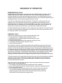
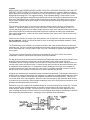
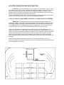
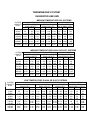
KRAMER
Bulletin
TTI - 803
F
April, 1997
Supercedes TTI-803E
Dated May 1984
THERMOBANK
SYSTEM
Installation and
Maintenance Manual
KRAMER 14230 Lochridge Boulevard / Covington, GA / 30014
Phone: 770-788-5800 Fax: 770-788-5820
www.kramerusa.net
THERMOBANK SYSTEM
Installation and Maintenance Manual
TABLE OF CONTENTS
PAGE
Table of Contents - Receiving - Uncrating - Work Safely!
Pre-installation - Rigging - Locating - Securing
Sequence of Operation - Refrigeration Cycle - Defrost Cycle
Piping Schematic for 3 thru 12 Horsepower - Base Mount Unit
2
3
4
5
Piping Instructions
Piping Schematic for 15 thru 70 Horsepower - Rail Mount Unit
Locating and Mounting Evaporators - Optimum Product Cooling
Suggested Refrigerant Line Sizes
Wiring - Setting Fan Cycling Controls - Filling the Bank with Water
6
7
8
9
10
Typical Thermobank Wiring Diagram
Leak Testing - Evacuation - Evacuation - Evacuation - Deep Vacuum
Charging - Minimum Charge Monitor - Initial Start-up - Pull down
Thermobank Control Settings - Function and Adjustment
Preventive Maintenance - Condensing Units and Evaporators
11
12
13
14
15
Service and Trouble Shooting
Service and Trouble Shooting - Ordering Replacement Parts
System Shut Down - Re-starting - Warranty
System Operation Recommendations for Longer Equipment Life
System Operation Checklist - Use Regularly to Insure Long Life
16
17
18
19
20
WORK SAFELY! DISCONNECT ALL POWER SOURCES BEFORE SERVICING!
CAUTION! WATER IN BANK IS HOT AND CAN SCALD! OPEN FILL PLUG SLOWLY!
RECEIVING AND UNCRATING
A responsible person should inspect the crating and equipment for possible shipping
damage. Care should be taken when uncrating to prevent damage. Avoid contact with
staples, nails, splinters and sharp edges. The equipment and coil surface have sharp
edges and contact should be avoided. Condensing units should be left on the shipping
skid until they are at actual point of installation. Check each shipment with the bill of
lading to make sure all items are received and in good condition. Check for concealed
shipping damage. Report any shortages or damage to the delivering carrier. Damaged
material is the responsibility of the carrier and a freight claim should be filed with them.
DO NOT return damaged equipment to the manufacturer without prior approval.
FOR ULTIMATE CUSTOMER SATISFACTION
This equipment should be installed, started up, checked for operation during and after pull
down, and fine tuned for optimum performance and long life at design conditions by
competent and experienced commercial or industrial refrigeration technicians that are
certified to purchase and recover refrigerants applied to commercial and industrial
refrigeration systems. EPA regulations must be observed.
System piping must be in accordance with good refrigeration practices. Dry nitrogen or an
inert gas should flow through piping during brazing. Polyol Ester(POE) lubricants
quickly absorb moisture from the atmosphere and their use necessitates keeping the
compressor and system closed to the atmosphere at all times.
Field wiring must conform to the equipment specplate data, wiring diagrams and all local
and national codes. Use only copper conductors.
This complete installation and service manual should be read and studied before starting
work. Read the instructions with the evaporator. You will be installing and operating the
POWER SAVING THERMOBANK , the first hot gas defrost system that will work year
round in all climates with floating head pressure control. During refrigeration, the head
pressure drops as the ambient drops, resulting in more capacity and reduced energy
consumption. There is no condenser flooding, no Winterstat adjustment, no extra
refrigerant charge and no oversized receiver.
THE THERMOBANK IS A PATENTED REFRIGERATION SYSTEM
RIGGING, LOCATING AND SECURING
Use good rigging practice and protect the units from damage. Always use spreader bars
when lifting with chain, cable or slings. Do not use the shipping skid as a permanent base.
Always install the condensing unit on a firm and level surface.
Condensing units must be located where there is an unrestricted supply of clean, fresh air.
Areas with corrosive or polluted air should be avoided. Do not locate units where air
discharge from one can enter into the air intake of another. Avoid locating units in
restricted spaces where heat will build up and heated air will enter the condenser. Space
condensing units at least one condensing unit height from the nearest wall. Make sure
there is room around the unit for regular inspection, maintenance and service.
Secure condensing units to pads or rails with adequate fasteners to prevent unit from
shifting or changing position. Mounting holes or slots are provided for proper size
fasteners. High winds can put substantial stress on mounting fasteners so take caution not
to undersize. Vibration isolation pads or springs are recommended.
Do not open sealed refrigeration lines until the unit has warmed up to the surrounding air
temperature. Never leave lines open more than a few minutes.
Follow the instructions included with the evaporator and page 8 for optimum performance.
SEQUENCE OF OPERATION
REFRIGERATION CYCLE
Hot discharge vapor flows from the compressor through the BANK heating coil, where normally
wasted condenser heat is stored in the warm water. Then, cooler discharge gas enters the
condenser through the normally open discharge solenoid valve. The condensed liquid from the
condenser flows to the receiver, where it is collected. No flow can occur through the bypass when the
discharge solenoid is open because the bypass solenoid is closed.
Liquid from the receiver flows through the filter/drier, Thermolator, and liquid solenoid to the
expansion valve. The Thermolator is simply a very high efficiency heat exchanger insuring
subcooled liquid to the expansion valve and superheated suction vapor to the compressor. The
liquid solenoid valve is controlled by the room thermostat, opening when cooling is required and
closing when the system has reduced the room temperature to satisfy the thermostat.
The liquid refrigerant fed by the expansion valve is vaporized in the evaporator. The vapor flows into
the suction line and through the Thermolator, suction filter, the open suction solenoid valve, and to
the compressor where it is recompressed.
DEFROST CYCLE
Initiation of the defrost cycle by the timer causes the following events:
1. Energizes the N.O. discharge solenoid, causing it to close.
2. Energizes the N.C. condenser bypass solenoid causing it to open.
3. Stops the evaporator fans.
4. Energizes the hot gas solenoid at the evaporator, causing it to open.
5. De-energizes the liquid solenoid, causing it to close.
6. Closes the suction solenoid.
The compressor continues to operate during defrost but the discharge vapor cannot flow to the
condenser because the discharge solenoid is closed. Therefore, the hot discharge vapor flows
directly to the liquid line through the open bypass solenoid. All the liquid in the liquid line flows into
the evaporator through the open hot gas solenoid, clearing the liquid. Then hot gas flows by way of
the liquid line, through the Thermolator, on to the evaporator. Part of the superheat of the hot gas is
removed in the Thermolator. The WARM VAPOR condenses in the evaporator providing a rapid
defrost. If discharge pressure becomes high, a pressure switch will momentarily open the
discharge solenoid and vapor will flow through the condenser and prevent compressor overloading.
The liquid condensed in the evaporator flows through the suction line and is directed to the holdback
valve by the closed suction solenoid. The holdback valve feeds the liquid into the BANK at a
controlled rate and pressure. The refrigerant evaporates in the BANK, cooling the water and
thereby abstracting the stored heat.
When the pressure in the defrosting evaporator rises to the setting of the defrost terminating
pressure switch, the following happens:
1. The discharge solenoid opens allowing unrestricted flow to the condenser.
2. Flow to the evaporator through the condenser bypass is stopped by the bypass solenoid.
3. The hot gas solenoid closes.
4. Suction solenoid and liquid solenoid remain closed. These two valves are controlled
by a "Post Defrost Pressure Switch" that senses evaporator pressure. When the
evaporator pressure falls to about 30 PSI, this switch opens both the suction and
liquid solenoid valves and starts the evaporator fans.
PIPING
WHEN USING HIGH TEMPERATURE SOLDER, PASS DRY NITROGEN THROUGH THE LINES TO
PREVENT OXIDE FORMING OR SCALING. When piping components located in different ambients,
always pipe from the warmer to the colder area. Line size charts are on page 9. Refer to the schematic
piping diagram on page 5 or 7 for suggested piping . Dual evaporator piping is shown below. An off
cycle or recycling pumpdown where the room thermostat controls the liquid line solenoid must be used.
Drain lines should be pitched 4 inches per foot and be short as possible. Each drain line must have a
trap in a warm ambient and the entire length must be protected from freezing using heat tracing tape
and insulation.
Pitch all suction lines at least 1/4 inch per foot in direction of flow to ensure oil return to compressor.
Install a "P" trap at the bottom of every suction riser and at 15 foot intervals for proper oil return. On
systems with long suction line runs subject to high ambient or solar load it may be necessary to insulate
some of the suction line to maintain the desired compressor superheat and return gas temperature.
With multiple evaporators, suction lines from each evaporator must "goose neck" into the suction main
with inverted traps.
Liquid lines also function as hot gas lines during defrost. Use the liquid line size charts on page 9 and
do not undersize. Liquid runs should be kept as short as possible and preferrably outdoors. Liquid
lines should not be insulated.
The Thermolator may be installed in any position outside the box, near the hole where the suction and
liquid line enter. The tee in the liquid line leading to the hot gas solenoid must be on the liquid outlet side
of the Thermolator and is usually inside the box. Only one Thermolator is required and supplied with
each system.
The liquid line solenoid should be installed near the expansion valve inlet. If there are multiple
evaporators, locate the solenoid near the branch to the first evaporator.
The hot gas line must tee into the liquid line between the Thermolator outlet and the liquid solenoid valve.
Install the hot gas solenoid in the hot gas line near the liquid line tee. Where more than one
Thermobank system is being installed, check the parts list to be certain the correct solenoid valves are
used for each system and each function. Connect the hot gas line to the hot gas lead at the drain pan
on evaporators with heated pans. On evaporators without heated pans a hot gas tee is supplied for
connecting the hot gas line at the expansion valve outlet. On multiple evaporator systems, install the
hot gas check valves supplied in the branch line to each evaporator hot gas inlet.
All piping must be adequately supported to prevent vibration and breakage. Tube clamps should have a
gasket surface. Inspect all piping when the equipment is in operation and add supports to prevent stress
or vibration. Line supports are inexpensive compared to downtime and refrigerant loss. Take care to
secure the liquid line at the evaporator. When the liquid solenoid opens and closes the liquid line has
a tendency to move forcefully. Without proper support the joints at the liquid solenoid, expansion valve,
distributor and distributor leads can fracture.
Expansion valves are supplied with standard clamps for securing the bulb to the suction line. The bulb
must be secured at the evaporator outlet, on the side of a horizontal run of suction line at the 4 or 8
o'clock position, before any traps. The bulb must be in uniform contact with clean copper tube and
must not bridge any fitting or uneven surface. Do not overtighten bulb clamps as deforming the bulb will
affect expansion valve performance. See page 19 for superheat recommendations.
LOCATING AND MOUNTING EVAPORATORS
LOCATING - Locate evaporators for the air pattern to cover all of the room. Do not
restrict the inlet or outlet air stream. Avoid placing evaporators above or close to doors. Direct
the air stream toward the door when possible or arrange to blow down a wide aisle. Allow
sufficient clearance for good air distribution and servicing the unit. Baffles may be required to
direct the refrigerated air to specific areas of the freezer.
Leave air space between rows, boxes, or cartons of product for the fastest product temperature
reduction and freezing. Direct the air to flow over and through the product.
COOL THE PRODUCT AND MINIMIZE THE ENTRY OF HUMID AIR INTO THE FREEZER.
MOUNTING - The ceiling structure must have adequate strength to support the
evaporators, controls, accessories, piping and refrigerant. We recommend using stainless steel
mounting hardware because plated steel fasteners and threads can corrode and become weak.
Use a MINIMUM 5/16 inch diameter fastener with LP evaporators, 3/8 inch with MS and CS
evaporators and 1/2 inch with TV and CM evaporators. Also use large flat washers.
Make sure evaporators are mounted with pan slope for proper condensate draining. The
condensate should run to an open drain. Drain lines should not be connected direct to a sewer
system. Never drain onto floors or walkways creating a hazard. Thoroughly seal the area where
lines or conduit go through the freezer wall. Air leaks will create safety hazards. Electrical
conduit must be internally sealed at the evaporator to prevent warm air and moisture being
drawn through the conduit into the freezer. If not sealed, moisture and ice will accumulate in the
evaporator.
Check the wiring diagram to determine the source for evaporator fan power. All fuses,
disconnect switches, and wire sizes should be selected in accordance with the National Electrical
Code and applicable local codes.
THERMOBANK SYSTEM
SUGGESTED LINE SIZE
MEDIUM TEMPERATURE R-22 SYSTEMS
SYSTEM
CAPACITY
BTUH
30,000
45,000
60,000
90,000
120,000
150,000
200,000
300,000
450,000
610,000
SUCTION LINE SIZE O.D. TYPE L
+15°F TO +10°F SST
+25°F TO +20°F SST
EQUIV LGTH FT.
EQUIV LGTH FT.
30
60
100
30
60
100
7/8
7/8
1 1/8
1 1/8
1 1/8
7/8
7/8
1 1/8
1 1/8
1 1/8
1 3/8
1 1/8
1 1/8
1 1/8
1 3/8
1 3/8
1 3/8
1 1/8
1 3/8
1 3/8
1 5/8
1 3/8
1 3/8 1 5/8
1 3/8
1 5/8
1 5/8
1 3/8
1 5/8 2 1/8
1 3/8
1 5/8
2 1/8
1 5/8
1 5/8 2 1/8
2 1/8
1 5/8
2 1/8
2 1/8
1 5/8
2 1/8
2 1/8
2 1/8
2 1/8
2 5/8
2 1/8
2 5/8
2 5/8
2 1/8
2 5/8
2 1/8
2 5/8
3 1/8
2 5/8
2 1/8
3 1/8
2 5/8
2 5/8
3 1/8
LIQUID LINE O.D.
COND. UNIT TO XVALVE EQUIV LGTH
30
60
100
1/2
1/2
5/8
1/2
5/8
5/8
5/8
5/8
7/8
5/8
7/8
7/8
7/8
7/8
7/8
7/8
7/8
1 1/8
7/8
1 1/8
1 1/8
1 1/8 1 3/8
1 3/8
1 3/8 1 5/8
1 5/8
1 5/8 2 1/8
2 1/8
MEDIUM TEMPERATURE R-404A OR R-507 SYSTEMS
SYSTEM
CAPACITY
BTUH
30,000
45,000
60,000
90,000
120,000
150,000
200,000
300,000
450,000
610,000
SUCTION LINE SIZE O.D. TYPE L
+15°F TO +10°F SST
+25°F TO +20°F SST
EQUIV LGTH FT.
EQUIV LGTH FT.
30
60
100
30
60
100
7/8
1 1/8
1 1/8
7/8
1 1/8
1 1/8
1 1/8
1 1/8
1 3/8
1 1/8
1 3/8
1 3/8
1 1/8
1 3/8
1 5/8
1 1/8
1 3/8
1 5/8
1 3/8
1 5/8
1 5/8
1 3/8
1 5/8
1 5/8
1 3/8
1 5/8
2 1/8
1 3/8
1 5/8
2 1/8
1 5/8
2 1/8
2 1/8
1 5/8
2 1/8
2 1/8
1 5/8
2 1/8
2 1/8
2 1/8
2 1/8
2 5/8
2 1/8
2 1/8
2 1/8
2 5/8
2 5/8
2 5/8
3 1/8
2 1/8
2 5/8
2 5/8
2 5/8
3 1/8
3 1/8
2 5/8
3 1/8
2 5/8
3 1/8
3 1/8
LIQUID LINE O.D.
COND. UNIT TO XVALVE EQUIV LGTH
30
60
100
1/2
5/8
5/8
5/8
7/8
7/8
7/8
7/8
7/8
7/8
7/8
1 1/8
7/8
1 1/8
1 1/8
1 1/8 1 1/8
1 3/8
1 1/8
1 1/8
1 3/8
1 1/8 1 3/8
1 5/8
1 5/8
1 3/8
1 5/8
2 1/8
1 5/8 2 1/8
LOW TEMPERATURE R-404A OR R-507 SYSTEMS
SYSTEM
CAPACITY
BTUH
8,000
16,000
25,000
35,000
45,000
60,000
80,000
100,000
150,000
200,000
300,000
400,000
-10°F SST
EQUIV LGTH
30
60
7/8
7/8
7/8
1 1/8
1 1/8
1 1/8
1 1/8
1 3/8
1 3/8
1 3/8
1 3/8
1 5/8
1 5/8
1 5/8
1 5/8
2 1/8
2 1/8
2 1/8
2 1/8
2 5/8
2 5/8
2 5/8
2 5/8
3 1/8
100
7/8
1 1/8
1 3/8
1 3/8
1 3/8
1 5/8
1 5/8
2 1/8
2 5/8
2 5/8
3 1/8
3 1/8
SUCTION LINE SIZE O.D. TYPE L
LIQUID LINE O.D.
-40 °F SST
COND. UNIT TO X-25 °F SST
EQUIV LGTH
VALVE EQUIV LGTH FT.
EQUIV LGTH FT.
30
60
100
30
60
100
30
60
100
7/8
7/8
7/8
7/8
1 1/8 1 1/8
1/2
1/2
1/2
1 1/8
1 1/8
1 1/8
1 1/8 1 3/8 1 3/8
1/2
1/2
1/2
1 1/8
1 1/8
1 3/8
1 3/8 1 3/8 1 5/8
1/2
1/2
5/8
1 3/8
1 3/8
1 3/8
1 3/8 1 3/8 1 5/8
5/8
5/8
5/8
1 3/8
1 3/8
1 3/8
1 3/8 1 5/8 1 5/8
5/8
7/8
7/8
1 3/8
1 5/8
1 5/8
1 5/8 1 5/8 1 5/8
5/8
7/8
7/8
1 5/8 1 5/8
1 1/8
1 5/8
1 5/8
2 1/8
2 1/8
7/8
7/8
2 1/8 2 1/8
1 1/8
2 1/8
2 1/8
2 1/8
2 1/8
7/8
7/8
2 1/8 2 5/8
1 3/8
2 1/8
2 1/8
2 5/8
2 5/8
1 1/8
1 1/8
2 5/8
2 5/8
2 5/8
2 5/8 2 5/8
2 5/8
1 1/8
1 1/8
1 3/8
2 5/8
3 1/8
3 1/8
2 5/8 3 1/8
3 5/8
1 1/8
1 3/8
1 5/8
3 1/8
3 1/8
3 5/8
3 1/8 3 5/8
3 5/8
1 3/8
1 5/8
1 5/8
WIRING
All field wiring should enter the control panel through electrical knockout bushings. All wiring should
be in compliance with local and national electrical codes. The equipment specplates are marked
with the electrical characteristics. Use only copper conductors of appropriate size.
Disconnect switches are supplied by the installer and should be installed to comply with governing
electrical codes.
Electrical connections have been securely tightened at the factory but they may loosen during
shipment. Before starting equipment, check all connections for tightness. Be sure power is
disconnected before tightening electrical connections. If any electrical components are located
outdoors use appropriate water-tight electrical fittings and conduit.
A wiring diagram is inside the control panel door. Wire components as shown on the wiring diagram.
All units must be grounded. After start-up, any vibrating armored cable should be secured and must
not contact refrigerant tubing. Typical THERMOBANK wiring is shown on page 11. The control
circuit should be energized at least 12 hours before charging and start-up to open the liquid line
solenoid and turn on the crankcase heater. This will assist the evacuation and dehydration process
and provide additional compressor protection during the charging and start-up.
FILL BANK WITH WATER
Unscrew the filler opening and fill the BANK with pure clean potable water. Do not use any glycol,
anti-freeze or other eutectic compound or additive A corrosion inhibitor was added at the
factory. Fill the BANK until the water level is 1/3 to 1/2 up in the water level sight glass. Screw filler
plug in securely. Do not use pipe dope - use teflon tape on threads. FILL THE BANK before
energizing the control circuit. Set the immersion heater thermostat to maintain a temperature of
120° to 150°F After the water is heated, the level will rise in the sight glass. Always maintain the
water level to be visible in the sight glass. Check water level often! The tubes inside the BANK
must be immersed in water for the system to function property. CAUTION! When servicing the
BANK, the water may be under pressure and is HOT and can scald! Remove the fill plug slowly!
FAN CYCLING CONTROLS ARE NOT FACTORY SET
Control settings will depend on the local climate conditions and the system suction temperature.
In warm climates it may be desirable to have all fans operating at most all times while North and
Central U.S. locations would want to cycle the fans. Ambient thermostat settings should not
overlap. Do not set pressure controls with close differential causing fans to short cycle. The
MINIMUM pressure differential should be 35 to 40 psi. Following are suggestions for initial
setting of ambient fan thermostats and header end fan pressure control.
SUGGESTED INITIAL SETTING OF CONDENSER FAN CYCLING CONTROL
NUMBER OF CONDENSER FANS
FAN
NO.
2
3
4
5
1
50°F Off - 55°F On
50°F Off - 55°F On
50°F Off - 55°F On
50°F Off - 55°F On
2
3
4
-- --- --- --
40°F Off - 45°F On
-- --- --
40°F Off - 45°F On
30°F Off - 35°F On
40°F Off - 45°F On
30°F Off - 35°F On
20°F Off - 25°F On
-- --
HEADER FAN (LAST FAN) PRESSURE CONTROL SETTINGS
Header fan may be Always On if desired. Low Temp. - Off 75 psi, On
120 psi. Medium Temp. - Off 115 psi, On 160 psi.
Ambient thermostats should have approximately 5 to 6°F differential.
Pressure controls should have approximately 40 to 60 psi differential.
Pressure control Off must be a MINIMUM of 30 psi above suction pressure.
ALL FAN CYCLING CONTROLS MUST BE FIELD SET BY THE INSTALLER
LEAK TESTING
After all refrigerant connections are made, have been visually inspected and thought to be
secure, add refrigerant until the system pressure is 20 to 30 PSI. Then pressurize with dry
nitrogen up to 100 to 140 PSI. ALWAYS USE A PRESSURE REDUCING REGULATOR.
Using an electronic leak detector, check all components and connections, both factory and
field made. Check the evaporator and condenser coils. Repair any leaks found and re-check
with the electronic detector until no leaks are found and the pressure holds steady, indicating
there are no leaks. If possible, leave the system pressurized overnight and if the pressure
remains steady, that is additional assurance there are no leaks. The system installation must
be leak free.
EVACUATION
For a well designed system that is properly installed and serviced to operate efficiently and
have a long and trouble free life, a DEEP EVACUATION is necessary. It takes both a deep
vacuum and filter-driers in a system for proper protection. The filter-driers will pick up
moisture, oxides, fibers, particles of metal, flux, and other materials that evacuation cannot
remove. Removing the AIR and MOISTURE from a system by using a deep vacuum is an
absolute necessity.
Only by using a rotary deep vacuum pump and an electronic deep vacuum gauge can the
installer be sure a system is dehydrated sufficiently to prevent early breakdown. By using a
rotary deep vacuum pump and the multiple evacuation method, an electronic deep vacuum
gauge can indicate whether the system has been adequately evacuated and whether a leak
exist during the evacuation. The installer must also be compliant to the EPA regulations and
use appropriate procedures to avoid venting refrigerants into the atmosphere.
A two-valve test manifold mounted on the vacuum pump is recommended. To shorten the
evacuation time and prevent erroneous gauge readings, install a vacuum line as large in
diameter and as short as practical. A minimum 3/8 inch OD copper tube or seamless metal
hose is recommended. The larger the system, the larger the vacuum line diameter should
be. Do not use neoprene hose for evacuation as it is not sufficiently vacuum tight for
evacuation or testing. Use a deep vacuum sealant on all line connections and fittings.
Be prepared to change the vacuum pump oil frequently. Use an oil that is specifically refined
for rotary deep vacuum pumps. A vacuum pump cannot create a vacuum less than the vapor
pressure of its sealing oil. Clean and dry deep vacuum oil is essential for proper system
evacuation and protection of the vacuum pump. If the vacuum pump cannot quickly pull
down to a low blank-off vacuum reading the oil must be changed. If the pump and oil are in
good condition it should quickly attain a 50 micron reading when blanked-off. We
recommend checking the pump condition with this test before attempting to evacuate a
refrigeration system.
We recommend evacuation with the electronic deep vacuum gauge holding at 500 microns or
less with R-22 systems and 300 microns or less on R-404A or R-507 systems after the final
evacuation. The vacuum gauge should hold steady on or below this reading 5 minutes after
the pump is closed off. Holding steady below this micron reading indicates the system is dry
and leak free. The compressor service valves must be open for the final evacuation so the
compressor and entire system is evacuated.
Break the vacuum with the proper system refrigerant and pressurize the system to 5 to 10 PSI
before removing the vacuum pump lines. DO NOT START THE COMPRESSOR WHILE THE
SYSTEM IS UNDER VACUUM. Do not use the compressor as a vacuum pump.
CHARGING
The control circuit should be energized at least 12 hours before charging and start-up to
open the liquid line solenoid and turn on the crankcase heater. This will assist the
evacuation and dehydration process and provide additional compressor protection during
the charging and start-up. It is good practice to charge refrigerants into a system through
a filter-drier in the charging line. This provides further assurance the refrigerant charge is
clean and dry.
Be sure the compressor discharge valve is open and the suction valve should be open 1
or 2 turns with a valve stem wrench attached for quick throttle adjusting. High and low
pressure gauges should be attached. Liquid charging is usually faster and if R-404A or R507 is used liquid charging is mandatory. We recommend breaking the final vacuum by
charging liquid refrigerant into the receiver outlet valve access or the area of liquid line
downstream from the receiver outlet. Approximately 40 to 60% of the system charge can
usually be injected into the receiver area before it is necessary to start the compressor so
the system will accept more liquid. It may be necessary to throttle the compressor suction
valve to keep suction pressures reasonable and prevent tripouts during the final charging
and pull-down.
Each Thermobank System is equipped with a Minimum-Charge-Monitor. This is the
application of two liquid sightglasses to the receiver, one on the inlet and one on the
outlet. When the system is properly charged, the outlet sightglass should be clear and the
inlet sightglass should have bubbles. If the system is undercharged both sightglasses will
bubble. Add refrigerant until the outlet sightglass stops bubbling. If both sightglasses are
clear, recover charge until the inlet sightglass bubbles. The outlet sightglass must have a
green dot indicating the system is dry.
INITIAL START-UP AND PULL DOWN
CONSTANT ATTENTION BY THE INSTALLER DURING THE START-UP AND PULL
DOWN IS NECESSARY. DO NOT JUST TURN EQUIPMENT ON AND WALK AWAY.
Pull down after start-up may present one or more of the following problems:
1. Higher than normal suction pressure. This can cause nuisance trip-out of compressor
overloads. It may be necessary to throttle the compressor suction valve to prevent
tripouts.
2. Pressure limiting expansion valves are used on low temperature systems and may
starve the evaporator during pull down. Oil loss from the compressor to the
evaporator may be observed. This oil should return to the compressor when design
room temperature is reached. It may be necessary to add oil and remove later.
3. High moisture load in new rooms may cause rapid frost build up on the evaporator.
It may be necessary to manually initiate a defrost.
4. The post defrost pressure control may cycle the evaporator fans and suction solenoid
valve. It is sometimes necessary to jump this control until the room has pulled down.
Take necessary steps to see the system starts up and pulls down safety. The suction
service valve should be left fully open after pull down.
THERMOBANK
HIGH PRESSURE CUTOUT
R-22
360 PSI
R-404A or R-507
395 PSI
DEFROST TERMINATION
R-22
160 PSI
R-404A or R-507
195 PSI
DEFROST DISCHARGE
R-22, 404A, 507
300 PSI
CONTROL SETTINGS
LOW PRESSURE CUTOUT
R-22, 404A, 507 (M)
5 PSI OUT, 20 PSI IN
R-404A or R-507 (L)
0 PSI OUT, 12 PSI IN
POST DEFROST
R-22, 404A, 507 (M)
35 PSI IN, 75 PSI OUT
R-404A or R-507 (L)
25 PSI IN, 40 PSI OUT
BANK HOLDBACK VALVE
R-22, 404A, 507
10 to 20 PSI
ADJUSTMENTS AND SETTINGS
1. HIGH PRESSURE CUTOUT CONTROL
This control is factory set but further adjustment may be necessary. Manual reset is required if the
control trips out.
2. LOW PRESSURE CUTOUT CONTROL
The Low Pressure Control is factory set for automatic recycling pumpdown but adjusting may be
necessary, depending on the lowest room or ambient temperature encountered. The control is auto reset.
3. DEFROST TERMINATION CONTROL
This control senses evaporator pressure and terminates on rise. The factory termination setting is
usually sufficient but if necessary to increase the defrost time, raise the termination setting by 10 PSI
increments only.
4. POST DEFROST CONTROL
The post defrost control is connected to sense pressure at the inlet of the suction solenoid valve. The
control supplied on medium temp systems can be field adjusted but the control on all low temp systems
is non-adjustable.
5. DEFROST DISCHARGE PRESSURE CONTROL
This control will function to momentarily open the discharge solenoid during defrost if discharge pressure
should rise above the setting. The control is auto reset.
6. BANK HOLDBACK VALVE
The Bank holdback is factory set to maintain a crankcase pressure of 10 to 20 PSI during defrost. If the
Bank suction outlet remains hot throughout the defrost, raise the valve setting. If floodback from the
Bank during defrost is observed, reduce the valve setting. Remove the protective cap and turn the stem
clockwise to raise the pressure or counter- clockwise to lower the pressure. Use a gauge on the suction
service valve when adjusting the holdback valve. Always replace the valve cap.
7. DEFROST TIMER
The timer should be set to the correct time and the frequency of defrost determined by the number of
pins in the timer disc. The factory setting is for one every 6 hours. The fail-safe is factory set for 20
minutes on medium temperature and 15 minutes on low temperature systems. The timer fail-safe will
terminate the defrost in the event the pressure control does not. If multiple systems are cooling one
room all timers must be synchronized for simultaneous defrost. Typical THERMOBANK defrost time is 5
to 10 minutes. Extra defrost pins are supplied.
8. OIL SAFETY CONTROL
The oil safety control is factory set and may not be field adjusted. Manual reset is required if the
control trips out.
PREVENTIVE MAINTENANCE
CONDENSING UNIT
Lubrication - Check Oil Level:
When a condensing unit is received the compressor oil level will be near the top of the oil level
glass and sometimes is slightly above. There is extra oil installed in the compressor to allow for
a limited amount of oil to circulate throughout the system with the refrigerant. The oil is clear
and can be difficult to see if above the glass. Once the compressor is started you may see some
foaming or bubbles in the oil level glass. The longer the compressor runs the lower the oil level
may go. The oil level may approach the bottom of the glass before the system cycles off or a
defrost occurs. Once the room is down to design temperature and a defrost has terminated
within the last hour, the oil level should be about 1/4 to 1/2 glass. The system should operate
most of the time with 1/8 to 1/2 glass of oil.
Oil is slowly circulated from the compressor to the evaporator during the cooling cycle and
should return from the evaporator to the compressor right after defrost. If oil collects
somewhere else in the system corrective measures are required. Excess oil is dangerous to the
compressor. Do not add oil just because the oil safety trips out.Thoroughly check out the
Trouble Shooting Oil Safety Trip-Out procedure on page 16-17 before adding oil. Correct any
condition that prevents oil return to the compressor.
Add only lubricant approved by the compressor manufacturer. POE (Polyol Ester) synthetic
lubricant must be used with R-404A or R- 507 systems. Take caution not to fill above 1/2 glass.
POE lubricants will quickly absorb moisture from the atmosphere. The entire system must be
kept sealed as much as possible. Do not leave the system or compressor open during breaks or
overnight
Cleaning the Condenser:
Remove lint, leaves, paper or other materials from the surface with compressed air or a vacuum
cleaner. Grease or dirt should be removed with a non-inflammable non-poisonous solvent or
detergent cleaner that will not attack aluminum or copper. Flush with clean water. The coil must
be kept clean at all times.
Regular Inspections - Check Water Level in Bank:
A regular preventive maintenance program and service contract are strongly recommended for
maximum system life and customer satisfaction. The BANK water level should be checked
every 90 days maximum, preferably more often. Weekly would be good. Operating with a low
water level will invite additional system problems. Fill out a Thermobank System Operation
Check List every 90 days and keep for future reference. Preventive Maintenance PAYS!
EVAPORATOR MAINTENANCE
Cleaning - Evaporators should be checked occasionally and cleaned of dirt
accumulation. The fan blades, fan guards and coil require frequent cleaning. Do not use
Ammonia or other cleaning chemicals that are corrosive to copper or aluminum. The drain pan
should be lowered for inspection and thoroughly cleaned to prevent debris from plugging or
restricting the drain. Make sure the drain connection area is clean and clear. Disconnect
electrical power to the evaporator when inspecting or cleaning.
Operating Inspection - A few minutes after a defrost termination, check the unit to
be sure the coil and drain pan are clear of all frost and ice. Do not allow ice to accumulate or
build up on any part of the coil or drain pan. Fan blades and guards should also be clear of frost
and ice. Manually remove any ice accumulation. Refer to Service and Trouble Shooting on
page 16. Make sure all motors and fans are operating. If uneven frosting is observed, look for
air leaking into the room. Eliminate all air leaks for optimum evaporator performance and energy
savings.
SERVICE AND TROUBLE SHOOTING
HIGH HEAD TRIP ON DEFROST
Nuisance trip on high head during defrost can be caused by one or more of the
following: (1) Bypass solenoid valve stuck closed; (2) Receiver inlet valve closed; (3)
Receiver outlet (king) valve closed; (4) Plugged filter/drier; (5) Hot gas solenoid fails to
open; (6) Defrost termination pressure switch fails to close; (7) Timer fails to terminate
on impulse to X terminal.
FAILURE TO DEFROST
Defrost failure without high head tripout can be caused by the following: If frost, not
ice, is plugging the fins check for (1) Timer not running; (2) Short in control circuit to
timer X terminal causing timer to terminate instantly after initiation; (3) Fault in timer
causes defrost to terminate instantly after initiation; (4) Timer switch broken. If ice, not
frost, is in the coil immediately pumpdown system until the coil has been manually
cleaned of all ice. Do not attempt to clear ice by increasing defrost time as this will
damage the coil. Check for (1) Plugged or frozen drain; (2) Evaporator pitched away
from drain; (3) Multiple evaporators with defrost not simultaneous; (4) Defrost
termination pressure switch set too low (Increase defrost pressure/time after coil has
been cleaned of all ice with warm water).
If fans or guards are frosted look for: (1) Excessive infiltration into the room; (2) High
latent load from wet product; (3) Excessively long defrost (Check terminator operation
and reduce termination pressure; (4) Defrost too infrequently (Add defrost pins in
timer); (5) Multiple systems with non-simultaneous defrost (Synchronize timers); (6)
Too many defrost per day. Very light frost loads may vaporize off the coil instead of
melting off as water. Remove a defrost pin.
TRIP ON DISCHARGE LINE THERMOSTAT (Carlyle Compressors Only)
Use a recorder to find out when the trip occurs with respect to day, night, and defrost. If
day, especially afternoon, suspect high head or hot Bank. If night, suspect low suction
pressure. If just before defrost, suspect frosted coil. If during defrost, suspect hot
Bank. Correct the condition causing the tripout. It may be necessary to insulate the
suction line or lower the thermostat setting on the Bank immersion heater. Adjust the
expansion valve for correct superheat.
OIL SAFETY TRIPOUT
Low oil level In sight glass when found off.
(1) Poor suction piping will hold up oil: Vertical risers must have "P" traps at bottom.
Horizontal lines must be pitched toward compressor 1/4 inch per foot. (2) Starved
evaporators will hold up oil: Adjust the expansion valve or replace if faulty. System
may be low on charge. The filter/drier may be plugged. High liquid line risers cause
flash gas at expansion valve. (3) Floodback is diluting the oil, making it foam so the
pump cannot develop enough oil pressure: Check the evaporator to make sure all fans
are operating and the coil is not blocked. Check expansion valve operation and adjust
superheat if too low. The liquid solenoid, hot gas solenoid, or suction solenoid may be
stuck open. Check the Thermobank water level and immersion heater. The holdback
valve setting may be too high or the bellows may be leaking causing the valve to
overfeed. The post defrost may be too short or the post defrost pressure switch may
be defective. A hot gas check valve may be stuck open.
(4) Incorrect or no recycling pumpdown: A recycling pumpdown with the room
thermostat controlling the liquid solenoid valve is mandatory. (5) Short of oil: On new
systems it is often necessary to add oil, but only one time. If low oil level continues to
be a problem too much oil is being tost or trapped in the system. Check all of the
suggestions mentioned before adding oil a second time. (6) Optional oil separator oil
return port plugged or float leaking. (7) Suction accumulator metering orifice plugged: If
the metering orifice is plugged the accumulator will fill with oil. (8) Low pressure control
set too tow or defective: The compressor will not shut off or takes too long to shut off
on pumpdown.
Oil level OK when found off.
(1) Extremely low crankcase pressure: May be caused by a starved evaporator or the
low pressure control set too tow or defective. (2) Low oil pressure observed even with
oil level OK: The oil pump may not be functioning. Check for reversed compressor
rotation. The compressor main or rod bearings may have excessive wear. The oil
strainer may be plugged. (3) Short Cycling: If the room thermostat calls for cooling and
the liquid solenoid is energized and open check for; incorrect adjustment of tow
pressure control, plugged filter/drier, expansion valve adjustment and operation,
operation of evaporator fans, blocked evaporator coils, system low on refrigerant. If the
room thermostat is satisfied and the liquid solenoid is de-energized and closed check
for; leaking liquid solenoid (frost at valve outlet), leaking hot gas solenoid, oil separator
float leaking or stuck, broken discharge valve or valve plate gasket. (4) Post defrost
too long: Adjust post defrost control to higher setting. (6) Floodback to compressor
generating foam: Expansion valve superheat too tow, blocked evaporator coil,
holdback valve at Bank set too high, tow water level in Bank, Bank too cold (check
power to Bank heater, the Bank heater and heater thermostat
OIL SAFETY TRIPOUT - CAUTION
Refrigerant may condense in oil after tripout and raise oil level. Also, after an oil safety
tripout, the liquid line solenoid will be open. To prevent floodback when the control is
reset, it may be necessary to throttle the compressor suction valve until the system
stabilizes. See PROCEDURE FOR RE-STARTING on page 18.
SUCTION ACCUMULATOR (Standard on parallel piped dual compressor units) The
accumulator is a safety device. It should contain very little if any liquid refrigerant during
normal operation. If persistent floodback keeps the accumulator partly full of liquid
refrigerant, find the source of floodback and correct it.
REPLACEMENT PARTS
Keep this instruction bulletin for later reference when performing regular preventive
maintenance or corrective service. When ordering replacement parts from the factory,
be certain to state the complete model number and serial number marked on the
KRAMER specplate. Clearly describe the item required by size, function, model
numbers or markings, and state the quantity you are ordering. This will ensure prompt
and accurate handling of your order. Replacement compressors and compressor parts
must be secured from your local compressor wholesaler.
SYSTEM SHUTDOWN
There are two toggle switches in the control panel. One is labeled "Compressor
Pilot" This switch is in the compressor starter pilot circuit and should be used by the
serviceman only for emergencies since it disables the pumpdown cycle. This switch
simply turns the compressor on or off. The switch labeled "Pumpdown" closes the liquid
solenoid, stops the evaporator fans and prevents defrost. The timer, however,
continues to operate. Use the "Pumpdown" switch for shutting down a normally
operating system for short or long periods. If the compressor is turned off by the
"Compressor Pilot" switch or any other manner than "Pumpdown", be sure to follow
PROCEDURE FOR RE-STARTING to minimize potential for compressor damage.
PROCEDURE FOR RE-STARTING
Do not just turn machines on and walk away! A compressor may be off for a long
period of time with the pumpdown inoperative for one of the following reasons:
1. Stoppage on overload, oil safety, high head or other lockout device.
2. Disconnect switch inadvertently pulled.
3. Power failure.
4. New installation is charged, but startup delayed without pumping down.
During an extended shutdown resulting from any of the above conditions, or on initial
startup, liquid refrigerant may flood the evaporator or compressor crankcase. It is
necessary to carefully clear these components of liquid to prevent compressor damage.
This can be accomplished by doing the following:
1. Close the liquid solenoid and stop evaporator fans by placing "Pumpdown" switch
in the OFF position.
2. Reset controls which may have tripped.
3. Operate the compressor in very short bursts, starting with 1 or 2 seconds and
gradually increasing the time until the liquid is cleared out. Use the "Compressor
Pilot" switch to accomplish this. Stop the machine instantly if knocking is observed.
4. Watch the oil level and suction pressure carefully. Rapid boiling of refrigerant in
the crankcase may lower the oil level dangerously. Add oil if necessary. Do not
operate continuously at extra low vacuum.
5. After you are sure the liquid is boiled off, re-start the evaporator fans and re-open
the liquid solenoid by turning the "Pumpdown" switch ON. Attend the system as
you would during initial startup. Do not just turn on and walk awayl
WARRANTY
One Year Limited Warranty: Seller warrants against defects in materials and
workmanship in products which it manufactures for (1) year from date of installation, or
up to (15) months from date of shipment, whichever occurs first. This guarantee does
not include any labor or other charges made outside of Seller's factory for the
replacement or repair of defective parts.
Four Year Extended Warranty: May be purchased on the compressor only. Contact
your Kramer Sales Representative for details and price. Other parts and labor are not
included.
Any deviation from correct installation and service practice, operation outside of
recommended temperature range, or that outlined in these instructions will be sufficient
cause for withdrawing all warranties.
EVAPORATOR SUPERHEAT
Normally 6° to 12° is acceptable on most refrigeration systems. Preferably 6° to 8° on
low temperature systems and 8° to 10° on medium temperature systems. Obtain
evaporator superheat by measuring the suction line temperature at the expansion valve
bulb. Obtain pressure at tap on evaporator suction connection and convert to
temperature with pressure-temperature chart. Subtract the converted temperature from
the measured temperature and the difference is superheat at the evaporator. Obtain
the desired superheat by adjusting the expansion valve.
COMPRESSOR SUPERHEAT
To improve compressor life expectancy 25° to 40° of compressor superheat is
preferred. Copeland recommends a MINIMUM of 26* superheat at the compressor.
Obtain compressor superheat by measuring suction line temperature about 6 to 12
inches from the compressor service valve. Obtain pressure at the suction service valve
and convert to temperature with pressure-temperature chart. Subtract the converted
temperature from the measured temperature and the difference is superheat at the
compressor.
RETURN GAS TEMPERATURE
Although compressors may be capacity rated with 65°F return gas most tow
temperature systems should not be operated at that condition. A 65°F return gas is
usually acceptable on medium temperature systems. We recommend a 20°F to 40°F
maximum return gas temperature on tow temperature systems. Higher return gas
temperatures on low temperature systems may cause compressor overheating and
shorten compressor life. Always maintain a minimum 20° superheat at the compressor.
If necessary, insulate the suction tine on tow temperature systems to improve the return
gas temperature and superheat at the compressor.
DISCHARGE LINE TEMPERATURE
The discharge line temperature should be measured about 6 inches down line from the
compressor discharge service valve. This temperature has a direct relationship to
internal temperatures in the compressor. A discharge line temperature of 220°F or
tower is desirable and will improve compressor life expectancy. Maintaining a discharge
line temperature below 220°F prevents oil breakdown, prevents excess wear on internal
parts, and is assurance the compressor is not overheating. Copeland recommends a
MAXIMUM discharge line temperature of 225°F.
There is a relationship between discharge line temperature and return gas temperature.
Lowering the return gas temperature by insulating the suction line will usually tower the
discharge line temperature about the same degree.
Make sure tow temperature compressors have a direct air blast over the compressor
body. This air blast is essential to maintain proper cooling of tow temperature
compressors.
An operational check and fine tuning to the above is recommended after the room has
pulled down to operating temperature and the outdoor ambient is above 70°F. To
simulate design conditions the condenser face can be partially blocked (Do not block
condenser air blast cooling compressor body) to raise head pressure.