1
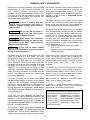
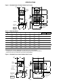
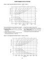
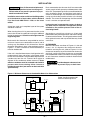
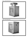
(S) RISM-9
J30-05380A
INSTALLATION AND SERVICE MANUAL
OUTDOOR ROOFTOP GAS-FIRED DUCT FURNACE
(NATURAL OR POWER VENTED)
ATTENTION: READ THIS MANUAL AND ALL LABELS ATTACHED TO THE UNIT CAREFULLY
BEFORE ATTEMPTING TO INSTALL, OPERATE OR SERVICE THESE UNITS! CHECK UNIT DATA
PLATE FOR TYPE OF GAS AND ELECTRICAL SPECIFICATIONS AND MAKE CERTAIN THAT THESE
AGREE WITH THOSE AT POINT OF INSTALLATION. RECORD THE UNIT MODEL AND SERIAL No.(s)
IN THE SPACE PROVIDED. RETAIN FOR FUTURE REFERENCE.
Model No.
Serial No.
SAVE THIS MANUAL
FOR YOUR SAFETY
The use and storage of gasoline or other flammable vapors and liquids in open
containers in the vicinity of this appliance is hazardous.
FOR YOUR SAFETY
If you smell gas:
1. Don’t touch electrical switches.
2. Extinguish any open flame.
3. Immediately call your gas supplier.
Improper installation, adjustment, alteration, service or maintenance can
cause property damage, injury or death. Read the installation, operating and
maintenance instructions thoroughly before installing or servicing this equipment.
Install, operate and maintain unit in accordance with manufacturer's
instructions to avoid exposure to fuel substances or substances from incomplete
combustion which can cause death or serious illness. The state of California has
determined that these substances may cause cancer, birth defects, or other
reproductive harm.
INSTALLER'S RESPONSIBILITY
Installer Please Note: This equipment has been test fired and inspected. It has been shipped
free from defects from our factory. However, during shipment and installation, problems such as
loose wires, leaks or loose fasteners may occur. It is the installer's responsibility to inspect
and correct any problems that may be found.
These units are certified by CSA International for operation on either natural or propane gas.
Read this manual and all labels attached to the unit carefully before attempting to install, operate or
service the following unit models:*
Outdoor Rooftop Duct Furnaces: QV(RT/PV)- (100, 150, 200, 250, 300, 350, 400) (H)(M)
(RT = Natural Vent; PV = Power Vent)
*Look in the direction of the unit air flow to determine whether the unit is right or left-hand accessible.
HVAC PRODUCTS
260 NORTH ELM ST., WESTFIELD, MA 01085
TEL: (413) 564-5540 FAX: (413) 562-5311
http://www.mestek.com
tracks, and push up into the top lip; swing and lower the
panel in place until it engages with the bottom panel.
Turn the screwhead on each latch clockwise. The screw
must turn freely one quarter turn before resistance is felt
in order for the lock to engage. If the latch does not hold,
turn the screw counter-clockwise several turns and
repeat the above procedure. Also refer to Figures 8Aa,
8b and 8c. for more specifications.
TABLE OF CONTENTS
RECEIVING/PRE-INSTALLATION
INSTRUCTIONS .................................................... 2
GENERAL SAFETY INFORMATION .................. 2, 3
SPECIFICATIONS
Dimensional Data ........................................ 4, 5
Performance and Specification Data ............... 5
Performance Data Curves ........................... 6, 7
INSTALLATION
Location/Mounting ................................... 2, 3, 8
Clearances ............................................... 4, 5, 8
Venting ............................................................. 9
Duct and Drain Specifications ........................ 10
Gas Connections ............................... 10, 11, 12
Electrical Connections ................................... 12
OPERATION
General Information ................................. 13, 14
Auto Spark Parts ............................................ 13
Controls ......................................................... 14
Gas Controls ...................................... 14, 15, 16
Air Distribution/Throughput ............................ 17
Lighting .................................................... 17, 18
Primary air Shutter/Pilot Adjustment .............. 18
Gas Input Adjustment .................................... 19
START-UP ...................................................... 19, 20
MAINTENANCE .............................................. 20, 21
TROUBLE SHOOTING GUIDE ........................ 22-25
REPLACEMENT PARTS ...................................... 26
WARRANTY .......................................................... 26
GAS EQUIPMENT CHECK SHEET ...................... 27
RECEIVING INSTRUCTIONS
Inspect shipment immediately when received to
determine if any damage has occurred to the
carton/crate during shipment.
After the unit has been uncrated, check for any visible
damage to the unit. On power vented units, check
motor position and turn blower wheel by hand to
determine if damage has occurred to these critical
parts.
If any damage is found, the consignee should sign the
bill of lading indicating such damage and immediately
file claim for damage with the transportation company.
PRE-INSTALLATION INSTRUCTIONS
When unit is received and uncrated check data plate
on unit for type of gas and electrical specifications and
make certain that these agree with those at point of
installation.
The following terms are used throughout this manual to
bring attention to the presence of potential hazards or to
important information concerning the product:
Open all disconnect switches
and secure in that position before installing the
unit. Failure to do so may result in personal
injury or death from electrical shock.
Indicates an imminently hazardous situation which, if not avoided, will result in
death, serious injury or substantial property
damage.
NOTICE: It is the equipment owner’s responsibility
to provide any scaffolding or other apparatus
required to perform emergency service or annual/
periodic maintenance to this equipment.
Indicates an imminently hazardous situation which, if not avoided, could result
in death, serious injury or substantial property
damage.
RIGGING
Rig the unit using either belt or cable slings. Use
spreader to protect the top of the unit when it is lifted.
Indicates an imminently hazardous
situation which, if not avoided, may result in minor
injury or property damage.
NOTICE: Used to notify of special instructions on
installation, operation or maintenance which are
important to equipment but not related to personal
injury hazards.
SERVICE ACCESS PANEL REMOVAL
To remove an access panel door, use the following
procedure: remove the two screws and two washers
from the louvered flue discharge area of the service
panel (power vent doors only). Each panel is held in
place with two “Grip” Latches. Using a slotted head
screw driver, turn the latch screwhead counter
clockwise. Using the handle provided, pull the panel
upwards. Pull the bottom of the panel out and lower the
panel to disengage it from the top lip. To replace an
access door panel, guide the panel door upwards on the
The furnace units are provided with two holes in the
base rail on each side of the unit. Slide pipes beneath
the unit through these holes and attach rigging to the
pipes for lifting the unit.
LOCATION
Before placing the rooftop unit in its permanent
location, make certain that the roof is capable of
carrying the additional load of this equipment. Check
the shipping weights given in Chart 2.
Refer to Figures 1, 2 and 6 and charts 1 and 2 for
adequate unit dimensions and required clearances.
MOUNTING
The units are mounted on skids and are suitable for
use on combustible flooring. It is recommended that the
skids be mounted either on level solid planking or steel
channels, but never on a soft tar roof where the skids
could sink and reduce the clearance between the
bottom panel and the roof.
–2–
GENERAL SAFETY INFORMATION
Roofcurb kits for rooftop gas heating units are shipped
knocked down. A curb kit contains (insulated) curb
rails, hardware, sealant, self-adhering rubber
gasketing, and installation instructions. Roof insulation,
cant strips, flashing, roof felts, caulking and nails must
be furnished by the installer. See separate curb
specifications from manufacturer.
vent through a protective grille, and the design of the
vent cap is such that the products of combustion are
discharged at the upper section of the cap. This cap is
shipped in a separate carton. It should be fastened in
position as shown in Figure 7 and should not be
altered in any way.
The Power Vented unit has a power venting system
with the inlet and discharge grille located in the upper
section of the side access panel. This balanced flue
design also performs well under all wind conditions.
Failure to comply with the
general safety information may result in
extensive property damage, severe personal
injury or death!
Do not alter the unit heater in
any way or damage to the unit and/or severe
personal injury or death may occur!
Never service any component
without first disconnecting all electrical and
gas supplies to the unit or severe personal
injury or death may occur!
Ensure that all power sources
conform to the requirements of the unit heater or
damage to the unit will result!
All internal parts of the standard unit are fabricated
from aluminized steel. Standard burners are pressed
aluminized steel and have a stainless steel burner port
protector and air shutters. All internal and external
jacket parts are fabricated from galvanized steel.
Stainless steel heat exchangers, burners and flue
collectors are optional. An optional 321 or 409 stainless
steel heat exchanger is highly recommended for the
following applications:
1) When the entering air temperature is below
40°F (4.4°C).
2) When the furnace is installed downstream of a
cooling coil section.
Installation must be made in accordance with local
codes, or in absence of local codes, with ANSI
Standard Z223.1-1999 (N.F.P.A. No. 54) National Fuel
Gas Code, or the latest edition. All of the ANSI and
NFPA Standards referred to in these installation
instructions are those that were applicable at the time
the design of the appliance was certified. The ANSI
Standards are available from the American Gas
Association, 1515 Wilson Boulevard, Arlington, Virginia
22209. The NFPA Standards are available from the
National Fire Protection Association, Batterymarch
Park, Quincy, MA 02269.
A pilot burner plate is provided for access to the pilot
burner and ignition systems without removing the
burner drawer. Clearances between the external unit
and obstruction must be sufficient for proper servicing
of pull-out drawer. See Figures 1 and 2 for this
clearance.
If installed in Canada, the installation must conform
with local building codes, or in absence of local building
codes, with current CGA-B149.1 “Installation Codes for
Natural Gas Burning Appliances and Equipment” or
CGA-B149.2 “Installation Codes for Propane Gas
Burning Appliances and Equipment”. These outdoor
duct furnaces have been designed for and certified to
comply with CGA 2.8.
Special orifices are required for installations above
2000 ft. (610 m). Check all local codes.
These units have been designed and certified for
outdoor use only, and may be located on the roof of the
building or at any convenient location external of the
building to be heated. The input range is 100,000 BTU/
HR. (29.3 kW) to 400,000 BTU/HR. (117.1 kW) in 50,000
BTU/HR. (14.6 kW) increments.
The outdoor units are certified for operation on either
natural or propane gas. If a unit is to be installed at an
altitude exceeding 2000 ft. (610 m) above sea level,
derate the input by 4% for each 1000 foot rise (305 m
rise) above sea level. Check all local codes.
In Canada, if a unit is to be installed at altitudes of
2000 ft. (610 m) to 4500 ft. (1372 m), the unit must be
orificed to 90% of the normal altitude rating.
Unless otherwise specified, the following conversions
may be used for calculating SI unit measurements:
1 inch = 25.4 mm
1000 Btu/Cu. Ft. = 37.5 MJ/m3
1 foot = 0.305 m
1000 Btu per hour = 0.293 kW
1 gallon = 3.785 L
1 inch water column = 0.249 kPa
1 pound = 0.435 kg liter/second = CFM x 0.472
1 psig = 6.894 kPa meter/second = FPM ÷ 196.8
1 cubic foot = 0.028 m3
The venting is an integral part of the unit and must not
be altered in the field. The Natural Vented units are
equipped with a vent cap which is designed for gravity
venting. Air for combustion enters at the base of the
–3–
SPECIFICATIONS
Figure 1 - Standard Natural Vented Outdoor Duct Furnace
1" (25)
Typ.
A
26"
(660)
C (Typ.)
Vent Cap
Is Shipped
In Separate
Carton
Gas
Connection
CL
D
19"
(483)
Opening
1-1/8" (29)
Typ. Duct
Flange
Electrical
Connections
39"
(991)
10-1/8"
(257)
5-1/16"
(129)
5/8" (16) Typ.
Anchor Hole
Location
DFR3538A
TFR3779A
B
Opening Typ.
8-3/4"
(222)
31-1/4"
(794)
*
F
4" (102)
13/16" (21) Typ.
Anchor Hole
Location
K
Chart 1 - Dimensional/Data
CAPACITY
(CA)
10
15
20
25
30
35
40
A
32-7/8
(835)
32-7/8
(835)
43-7/8
(1114)
43-7/8
(1114)
54-7/8
(1394)
54-7/8
(1394)
60-3/8
(1534)
B
15-9/16
(395)
18-5/16
(465)
23-13/16
(605)
29-5/16
(745)
34-13/16
(884)
40-5/16
(1024)
45-13/16
(1164)
C
12
(305)
21-1/2
(546)
23-1/2
(597)
23-1/2
(597)
26
(660)
26
(660)
26
(660)
US
D
11
(279)
16
(406)
16
(406)
16
(406)
17-1/2
(445)
17-1/2
(445)
17-1/2
(445)
CANADA
D
20-11/16
(525)
25-3/16
(640)
25-3/16
(640)
25-3/16
(640)
26-11/16
(678)
26-11/16
(678)
26-11/16
(678)
*F
19-3/8
(492)
23-1/2
(597)
26-1/4
(667)
34-1/2
(876)
37-1/4
(946)
45-1/2
(1156)
51
(1295)
K
30-3/16
(767)
30-3/16
(767)
41-3/16
(1046)
41-3/16
(1046)
52-3/16
(1326)
52-3/16
(1326)
57-11/16
(1465)
GAS INLET
NAT
LP
1/2
1/2
1/2
1/2
1/2
1/2
3/4
1/2 OR 3/4
3/4
1/2 OR 3/4
3/4
1/2 OR 3/4
3/4
1/2 OR 3/4
NOTE:
DIMENSIONS ARE IN INCHES, DIMENSIONS IN PARENTHESIS ARE IN MILLIMETERS.
* “F” DIMENSION IS THE RECOMMENDED CLEARANCE TO SERVICE THE BURNER DRAWER(S).
REFER TO FIGURE 6 FOR ADDITIONAL CLEARANCE REQUIREMENTS.
Figure 2 - Standard Power Vented Outdoor Duct Furnace
1" (25)
Typ.
26"
(660)
A
CL
Flue
Product
Outlet
Combustion
Air Inlet
Gas
Connection
19"
(483)
Opening
1-1/8" (29)
Typ. Duct
Flange
Electrical
Connections
39"
(991)
10-1/8"
(257)
5-1/16"
(129)
5/8" (16) Typ.
Anchor Hole
Location
DFR3541A
TFR3779 A
B
Opening Typ.
8-3/4"
(222)
31-1/4"
(794)
*
F
–4–
K
4" (102)
13/16" (21) Typ.
Anchor Hole
Location
Chart 2 - Performance and Specification Data
CAPACITY
MBH
100
NATURAL VENT
150
200
250
300
350
400
100
POWER VENT
150
200
250
300
350
400
**
100H
NATURAL VENT
150H
200H
250H
300H
350H
400H
**
100H
150H
POWER VENT
200H
250H
300H
350H
400H
INPUT
RATING
BTU/Hr
(kW)
OUTPUT
RATING
BTU/Hr
(kW)
100,000
(29.3)
150,000
(43.9)
200,000
(58.6)
250,000
(73.2)
300,000
(87.8)
350,000
(102.5)
400,000
(117.1)
80,000
(23.4)
118,500
(34.7)
158,000
(46.3)
197,500
(57.8)
237,000
(69.4)
276,500
(81.0)
316,000
(92.5)
100,000
(29.3)
150,000
(43.9)
200,000
(58.6)
250,000
(73.2)
300,000
(87.8)
350,000
(102.5)
400,000
(117.1)
79,000
(23.1)
118,500
(34.7)
158,000
(46.3)
197,500
(57.8)
237,000
(69.4)
276,500
(81.0)
316,000
(92.5)
100,000
(29.3)
150,000
(43.9)
200,000
(58.6)
250,000
(73.2)
300,000
(87.8)
350,000
(102.5)
400,000
(117.1)
80,000
(23.4)
120,000
(35.1)
160,000
(46.9)
200,000
(58.6)
240,000
(70.3)
280,000
(82.0)
320,000
(93.7)
100,000
(29.3)
150,000
(43.9)
200,000
(58.6)
250,000
(73.2)
300,000
(87.8)
350,000
(102.5)
400,000
(117.1)
80,000
(23.4)
120,000
(35.1)
160,000
(46.9)
200,000
(58.6)
240,000
(70.3)
280,000
(82.0)
320,000
(93.7)
F*
Temp. Rise
Min.
F Deg.
Static
Clearance
(C Deg.)
in. of Water
in.
Min. - Max.
(KPa)
(mm)
EFF.
%
MIN.
CFM
(cu. m/s)
MAX.
CFM
(cu. m/s)
80
823
(0.388)
1,219
(0.575)
1,626
(0.767)
2,032
(0.959)
2,438
(1.151)
2,845
(1.343)
3,251
(1.534)
2,469
(1.165)
3,657
(1.726)
4,876
(2.301)
6,096
(2.877)
7,315
(3.453)
8,534
(4.028)
9,753
(4.603)
30
(17)
30
(17)
30
(17)
30
(17)
30
(17)
30
(17)
30
(17)
-
90
(50)
90
(50)
90
(50)
90
(50)
90
(50)
90
(50)
90
(50)
2
(0.50)
2
(0.50)
2
(0.50)
2
(0.50)
2
(0.50)
2
(0.50)
2
(0.50)
7-1/8
(181)
11-1/4
(286)
14
(356)
22-1/4
(565)
34
(864)
33-1/4
(845)
38 3/4
(984)
813
(0.384)
1,219
(0.575)
1,626
(0.767)
2,032
(0.959)
2,438
(1.151)
2,845
(1.343)
3,251
(1.534)
2,438
(1.151)
3,657
(1.726)
4,876
(2.301)
6,096
(2.877)
7,315
(3.453)
8,534
(4.028)
9,753
(4.603)
30
(17)
30
(17)
30
(17)
30
(17)
30
(17)
30
(17)
30
(17)
-
90
(50)
90
(50)
90
(50)
90
(50)
90
(50)
90
(50)
90
(50)
2
(0.50)
2
(0.50)
2
(0.50)
2
(0.50)
2
(0.50)
2
(0.50)
2
(0.50)
7-1/8
(181)
11-1/4
(286)
14
(356)
22-1/4
(565)
34
(864)
33-1/4
(845)
38-3/4
(984)
1,235
(0.583)
1,852
(0.874)
2,469
(1.165)
3,086
(1.457)
3,704
(1.748)
4,321
(2.040)
4,938
(2.331)
3,704
(1.748)
5,556
(2.622)
7,407
(3.496)
9,259
(4.370)
11,111
(5.244)
12,963
(6.119)
14,815
(6.993)
20
(11)
20
(11)
20
(11)
20
(11)
20
(11)
20
(11)
20
(11)
-
60
(33)
60
(33)
60
(33)
60
(33)
60
(33)
60
(33)
60
(33)
2
(0.50)
2
(0.50)
2
(0.50)
2
(0.50)
2
(0.50)
2
(0.50)
2
(0.50)
7 1/8
(181)
11-1/4
(286)
14
(356)
22-1/4
(565)
34
(864)
33-1/4
(845)
38-3/4
(984)
1,235
(0.583)
1,852
(0.874)
2,469
(1.165)
3,086
(1.457)
3,704
(1.748)
4,321
(2.040)
4,938
(2.331)
3,704
(1.748)
5,556
(2.622)
7,407
(3.496)
9,269
(4.375)
11,111
(5.244)
12,963
(6.119)
14,815
(6.993)
20
(11)
20
(11)
20
(11)
20
(11)
20
(11)
20
(11)
20
(11)
-
60
(33)
60
(33)
60
(33)
60
(33)
60
(33)
60
(33)
60
(33)
2
(0.50)
2
(0.50)
2
(0.50)
2
(0.50)
2
(0.50)
2
(0.50)
2
(0.50)
7-1/8
(181)
11-1/4
(286)
14
(356)
22-1/4
(565)
34
(864)
33-1/4
(845)
38-3/4
(984)
79
79
79
79
79
79
79
79
79
79
79
79
79
80
80
80
80
80
80
80
80
80
80
80
80
80
80
* See figures 1 and 2.
Nat.
Gas
Inlet
in.
L.P.
Gas
Inlet
in.
1/2
1/2
1/2
1/2
1/2
1/2
3/4
1/2 OR 3/4
3/4
1/2 OR 3/4
3/4
1/2 OR 3/4
3/4
1/2 OR 3/4
1/2
1/2
1/2
1/2
1/2
1/2
3/4
1/2 OR 3/4
3/4
1/2 OR 3/4
3/4
1/2 OR 3/4
3/4
1/2 OR 3/4
1/2
1/2
1/2
1/2
1/2
1/2
3/4
1/2 OR 3/4
3/4
1/2 OR 3/4
3/4
1/2 OR 3/4
3/4
1/2 OR 3/4
1/2
1/2
1/2
1/2
1/2
1/2
3/4
1/2 OR 3/4
3/4
1/2 OR 3/4
3/4
1/2 OR 3/4
3/4
1/2 OR 3/4
Net
Weight
lb.
(kg)
Shipping
Weight
lb.
(kg)
202
(92)
228
(103)
283
(128)
309
(140)
365
(166)
391
(177)
427
(194)
221
(100)
247
(112)
304
(138)
330
(150)
387
(176)
413
(187)
459
(208)
200
(91)
223
(101)
270
(123)
296
(134)
343
(156)
369
(167)
405
(184)
219
(99)
242
(110)
291
(132)
317
(144)
365
(166)
391
(177)
437
(198)
199
(90)
226
(103)
281
(127)
306
(139)
362
(164)
387
(176)
423
(192)
218
(99)
245
(111)
302
(137)
327
(148)
384
(174)
409
(186)
455
(206)
197
(89)
221
(100)
268
(122)
293
(133)
340
(154)
365
(166)
401
(182)
216
(98)
240
(109)
289
(131)
314
(142)
362
(164)
387
(176)
433
(196)
** “H” indicates low temperature rise furnace.
The clearances dimensions shown in chart #2 are the absolute minimum clearances for servicing the burner drawer. However, the clearances
shown in chart #1 are the recommended clearances for ease of servicing the unit.
–5–
PERFORMANCE DATA CURVES
Figure 3 - High Temperature Rise Duct Furnaces — 30-90 F° (17-50 C°)
Pressure drop through the heat exchanger is based on
the CFM throughput. The desired data is obtained in
the following manner:
1. Select heater size based on heat loss of the building
to be heated.
2. Select temperature rise desired.
3. Based on temperature rise, the horizontal line intersects heater temperature vs. CFM curve.
4. Follow vertical line down to select CFM.
5. For pressure drop selection, follow vertical CFM line
until it intersects the selected heater performance
curve vs. pressure drop.
6. Follow the horizontal pressure drop line to the left,
and read pressure drop of the selected heater.
Figure 4 - Low Temperature Rise Duct Furnaces — 20-60 F° (11-33 C°)
–6–
BYPASS SIZING INFORMATION
(BUILT ON THE JOB – NOT FURNISHED BY
FACTORY)
On occassion when a duct furnace is incorporated in
an air handling system, it may be desirable to handle a
total of more CFM than the duct furnace will pass at a
given static pressure drop and temperature rise. Therefore, it is necessary to arrange to bypass the additional
CFM required. The size of the bypass duct can be
determined by referring to the chart. This permits the
static pressure drop through the bypass to balance off
the drop through the heat exchanger. The bypass duct
is not factory furnished and must be built on the job by
the installer and a damper placed therin if required.
USE OF BYPASS CURVES
The width of the by-pass for CFM in excess of that
provided through the heater may be found in the
following manner:
1. Determine the CFM and pressure drop through the
heater based on the heating requirement
specifications.
2. Determine the additional CFM desired, over and
above the CFM for the heating requirements.
3. Using the pressure drop which was determined from
performance curves above, for the heating load,
locate this pressure drop on the by-pass curves.
Follow this curve until it intersects thevertical CFM
line for the excess CFM desired.
4. Follow horizontal line to left to obtain width of by-pass
duct.
Figure 5 - By-Pass Curve
–7–
INSTALLATION
Open all disconnect switches and
secure in that position before installing unit.
Failure to do so may result in personal injury or
death from electrical shock.
Installation must conform with local building codes,
or in the absence of local codes, with the National
Fuel Gas Code ANSI Z223.1-1999, or the latest
edition.
A heat loss study and a complete layout of the system
should be made first.
When locating the unit in its permanent location, make
certain that the roof is capable of carrying the additional
load of the equipment. Check the net weights from the
engineering data.
Make certain that clearances are provided for service,
minimum clearance to combustible material and to
venting cap. See below for this information. Service
clearance information is given in the engineering data in
Figures 1, 2 and 6. Clearances around secondary air
must be unobstructed.
If the unit is installed downstream of refrigeration coils,
condensate will form and collect in the bottom of the
heater. Drain connections are provided to dispose of this
condensate from the unit. Connect drain pipes to
dispose of this condensate where necessary. Ducts
which are outdoors must be insulated and sealed to
prevent water from entering either furnace or
building through duct (see section on duct and drain
specifications).
Ducts connected to duct furnaces shall have removable
access panels on both upstream and downstream sides
of the unit. These openings shall be accessible when the
unit is installed in service, and shall be of such size that
smoke or reflected light may be observed inside the
casing to indicate the presence of leaks in the heating
element. The covers for the openings shall be attached
in such a manner as to prevent leaks.
If a duct furnace is connected to a return air duct or
any other inlet air restriction, the appliance shall be
installed on the positive pressure side of the aircirculating blower.
Atmospheres containing solvents or chlorinated
hydrocarbons will produce corrosive acids when coming
in contact with the flames. This will greatly reduce the life
of the gas duct furnace and may void the warranty. Avoid
such areas.
CLEARANCES
Minimum clearances are shown in Figures 1, 2 & 6 and
charts 1 & 2. It is important that clearances be maintained for servicing the unit (refer to Figures 1 & 2 for
clearances necessary to pull out the burner drawer for
servicing), and that minimum clearances are provided
from combustible material and from the venting cap/top
of unit. Clearances around the outside air hood must be
unobstructed.
Provide adequate clearance from
combustibles to prevent injury or death from
fire.
Figure 6 - Minimum Clearances to Combustible Material or Obstructions
Power Vent Units required 36"
clearance above top of unit.
18"
(457)
5/16" (8) Typ.
36"
(914)
36"
(914)
5/16"
(8)
18"
(457)
Ductwork
18"
(457)
Natural
(or Power)
Vent
Furnace
5/16"
(8)
18"
(457)
Clearance
For Drawer
Pul-out
Air Flow
D3589A
D3589
*See figures 1 & 2 and charts 1 & 2.
–8–
VENTING
All venting installations shall be in accordance with the
latest edition of “Part 7, Venting of Equipment of the
National Fuel Gas Code, ANSI Z223.1-1999, or
applicable provisions of local building codes”.
Natural venting models are equipped with a vent cap
designed for natural venting. Air for combustion enters
at the base of the vent through a protective grille, and the
design of the vent cap is such that the products of
combustion are discharged at the upper section of the
cap. The cap is shipped in a separate carton. It should
be fastened in position as shown in Figure 7 and should
not be altered in any way.
Power vented models are designed with combustion
air inlet and flue products outlet located in the louvered
side access panel. Never locate these units in an area
where the flue products outlet may be directed at any
fresh air vents.See Figures 8a 8b, and 8c for
installation and servicing requirements.
Figure 8a - Power Venter Discharge Location
TOP VIEW
The venting is an integral part of
the unit and must not be altered in the field. If
altered, excessive carbon monoxide could be
produced.
Figure 7 - Vent Cap Assembly
(Natural Vented Furnaces Only)
Neoprene Washers
Screws
*These Surfaces (indicated with an asterisk in figures 8a & 8b)
MUST be flush and sealed at all times to ensure the proper
discharge of flue products from the unit.
1
AAAA
AAAA
AAA
2
These discharge flanges are equipped with special gasketing,
which must create an air tight seal connection around the louvers
of the access panel.
Secure in place the access door to the discharge adaptor using the
two screws and neoprene washers, then tighten the grip
latches (see service access panel removal section).
4
D3505
Figure 8b
3
D3591
NT
LEFT
FRO
R
RIGH
REA
T
D3591
FIELD INSTALLATION INSTRUCTIONS
1. Remove “Side Access Panel”.
2. Insert Vent Sleeve of “Vent Cap Assembly” (Item 1)
thru “Top Panel Assembly” (Item 2), and over Vent
Collar of “Flue Collector Assembly” (Item 3).
3. Align “Vent Cap Assembly” so it is square to “Top
Panel Assembly”.
4. Fasten with “Drill Screw” or “Sheet Metal Screw”
(Item 4) by reaching between “Flue Collector
Assembly” (Item 3) & “Top Panel Assembly” (Item
2), and drilling through vent sleeve of “Vent Cap
Assembly” into vent collar of “Flue Collector
Assembly”.
5. Replace “Side Access Panel”.
D3725
Figure 8c
NOTICE: If your unit is to be equipped with the
optional extended vent cap assembly, see the special
instructions supplied with the vent cap.
–9–
D4596
D4596
DUCT SPECIFICATIONS
Ductwork which is outdoors must be insulated and
sealed to prevent water from entering either furnace or
building through the duct. Do not alter the flange
connection for the duct attachment; air may bypass
and cause combustion problems. Be sure to properly
seal to avoid any air leakage (refer to Figures 1 and 2).
Ductwork connected to duct furnaces should have
removable access panels on both the upstream and
downstream sides of the unit. These openings should be
accessible when the unit is installed, and should be
sized so that smoke or reflected light can be observed
inside the casing to indicate the presence of leaks in the
heating equipment. The covers of the openings should
be attached in a manner that prevents leaks.
GAS CONNECTIONS
All gas piping should be installed in accordance with
local codes. It is required that a ground union be
installed adjacent to the manifold for easy servicing. On
vertical runs, a drip leg should be provided upstream of
the control manifold (see figure 9a). An additional shutoff must be located externally of the jacket enclosure
where required by local code. The location of this valve
must comply with the local codes. A 1/8-inch N.P.T.
plugged tapping, accessible for test gauge connection,
must be installed immediately upstream of the gas
supply connection to the unit. Field gas piping
recommendations are shown in Figure 9b.
It is recommended that the gas piping not be installed
through the bottom of the duct furnace bottom panel. If
piping must penetrate the duct furnace bottom panel, it
must be sealed to prevent water leakage.
To avoid equipment damage or
possible personal injury, do not connect gas
piping to this unit until a supply line pressure/leak
test has been completed. Connecting the unit
before completing the pressure/leak test may
damage the unit gas valve and result in a fire
hazard.
Do not rely on a shutoff valve to
isolate the unit while conducting gas pressure/leak
tests. These valves may not be completely shut off,
exposing the unit gas valve to excessive pressure
and damage. Do not overtighten the inlet gas piping.
This may cause stresses that would crack the valve.
The appliance must be isolated from the gas supply
piping system by closing its individual manual shutoff
valve during any pressure testing of the gas supply
piping system at test pressure equal to or less than
1/2 psig (3.5 kPa).
For additional piping information, refer to National Fuel
Gas Code ANSI Z233.1-1999, or latest edition.
Figure 9a - Drip Leg Installation
TO GAS LINE
ALTERNATE TO
GAS LINE
TO GAS CONTROLS
3 In. (Min.)
76mm. (Min)
DRIP LEG
D3587
D3587
Figure 9b - Field Piping Recommendations
Never use an open flame to detect
gas leaks. Explosive conditions may exist which
would result in personal injury or death.
NIPPLE
ELBOW
NIPPLE
The gas line should be supported so that no strain is
The gas line should be supported so that no strain is
placed on the unit. Pipe compounds which are not
soluble to liquid petroleum gases should be used on
threaded joints.
The appliance and its individual shutoff valve must be
disconnected from the gas supply piping system during
any pressure testing of that system at test pressure in
excess of 1/2 psig (3.5 kPa).
UNION
NIPPLE
ELBOW
NIPPLE
D3726
D3726
– 10 –
UNION
GAS CONNECTIONS (continued)
For the most satisfactory piping installation, the following
procedure should be followed. Make piping layout of the
whole installation and calculate the cubic feet of gas that
each supply pipe will carry. See piping example below.
NOTICE: If more than one gas duct furnace is to be
served by the same piping arrangement, the total
cu. ft./hr. input and length of pipe must be
considered.
Calculate the cubic feet of gas that each supply pipe will
carry:
NOTICE: If the gas duct furnace is to be fired with LP
gas, consult local LP gas dealer for pipe size
information. Heater installation for use with propane
(bottled) gas must be made by a qualified LP gas
dealer or installer. He will insure proper joint
compounds are used for making pipe connections;
that air is purged from lines; that a thorough test is
made for leaks before operating heater; and that it is
properly connected to propane gas supply system.
Btu/Hr.
1000 Btu Natural Gas/Cu. Ft.
= Cu. Ft. Per Hour of Gas to Unit (cfh)
Unit Kilowatt
37.3 Megajoules Natural Gas/Cu Meter
= Liters per second on Gas to Unit (l/s)
Before any connection is made to an existing line
supplying other gas appliances, contact the local gas
company to make certain that the existing line is of
adequate size to handle the combined load.
NOTICE: Contact your natural gas supplier for the
Btu/Cu. Ft. content of natural gas in your area. This
may be higher or lower than the nominal 1000 Btu/Cu.
Ft. used in this example:
Refering to the piping example in figure 10, the length of
pipe from the gas meter (A) to the most remote heater (E)
is 60 feet. This distance should be used for all of the
heaters when determining the pipe size required. Based
on the column marked 60 feet in chart 3, the piping for this
example should be sized as follows:
• 450 cfh is supplied from A to B, requiring
1-1/4 inch pipe.
• 200 cfh is supplied from B to C, requiring
1 inch pipe.
• 250 cfh is supplied from B to D, requiring
1 inch pipe.
• 100 cfh is supplied from D to E, requiring
3/4 inch pipe.
• 150 cfh is supplied from D to F, requiring
1 inch pipe.
Check all connections with a soap solution before
leaving job.
HYDRONIC MODULATING GAS CONTROL
(OPTIONAL)
On units equipped with hydraulic modulating gas control,
the temperature sensing bulb for the gas valve must be
field installed in the supply ductwork. Carefully uncoil the
capillary tubing to prevent kinking or sharp bends.
Do not bend the capillary tubing within
1/2" (12.7 mm) of its connection to the bulb or the
valve. Repeated bending may cause the tubing to leak
or break.
Center and fasten the temperature sensing bulb in the
supply ductwork at least one foot downstream of the
furnace section.
For SI calulations, refer to metric conversion chart in
general safety section of this manual.
Figure 10 - Example of Piping Layout for Determining Pipe Size
HEATER(S)
200 CFH
C
5 ft.
1.64 m.
10 ft.
3.48 m.
20 ft.
6.56 m.
10 ft.
3.28 m.
D
E
B
5 ft.
1.64 m.
20 ft.
6.56 m.
HEATER(S)
100 CFH
F
HEATER(S)
150 CFH
A
3588
D3588
GAS METER
– 11 –
Chart 3
GAS PIPE SIZE
Maximum Capacity of Pipe in Cubic Feet of Gas per Hour for Gas Pressures of 0.5 psig (3.5 kPa) or Less,
and a Pressure Drop of 0.5 Inch Water Column (124.4 Pa)
(Based on a 0.60 Specific Gravity Gas)
Nominal
Iron
Internal
Pipe Size Dia.
in.
1/2
3/4
1
1 1/4
1 1/2
2
2 1/2
3
4
Length of Pipe, ft. (Meters)
in.
10
20
30
40
(mm)
(3.0)
(6.1)
(9.1)
(12.2)
50
60
(15.2) (18.3)
70
80
90
100
125
150
175
200
(21.3)
(24.4)
(27.4)
(30.5)
(38.1)
(45.7)
(53.3)
(61.0)
0.622
175
120
97
82
73
66
61
57
53
50
44
40
37
35
(16)
0.824
(21)
1.049
(27)
1.380
(35)
1.610
(41)
2.067
(53)
2.469
(63)
3.068
(78)
4.026
(102)
(4.96)
360
(10.2)
680
(19.3)
1400
(39.6)
2100
(59.5)
3950
(112)
6300
(178)
11000
(311)
23000
(651)
(3.40)
250
(7.08)
465
(13.2)
950
(26.9)
1460
(41.3)
2750
(77.9)
4350
(123)
7700
(218)
15800
(447)
(2.75)
200
(5.66)
375
(10.6)
770
(21.8)
1180
(33.4)
2200
(62.3)
3520
(99.7)
6250
(177)
12800
(362)
(2.32)
170
(4.81)
320
(9.06)
660
(18.7)
990
(28.0)
1900
(53.8)
3000
(85.0)
5300
(150)
10900
(309)
(2.07)
151
(4.28)
285
(8.07)
580
(16.4)
900
(25.5)
1680
(47.6)
2650
(75.0)
4750
(135)
9700
(275)
(1.87)
138
(3.91)
260
(7.36)
530
(15.0)
810
(22.9)
1520
(43.0)
2400
(68.0)
4300
(122)
8800
(249)
(1.73)
125
(3.54)
240
(6.80)
490
(13.9)
750
(21.2)
1400
(39.6)
2250
(63.7)
3900
(110)
8100
(229)
(1.61)
118
(3.34)
220
(6.23)
460
(13.0)
690
(19.5)
1300
(36.8)
2050
(58.0)
3700
(105)
7500
(212)
(1.50)
110
(3.11)
205
(5.80)
430
(12.2)
650
(18.4)
1220
(34.5)
1950
(55.2)
3450
(97.7)
7200
(204)
(1.42)
103
(2.92)
195
(5.52)
400
(11.3)
620
(17.6)
1150
(32.6)
1850
(52.4)
3250
(92.0)
6700
(190)
(1.25)
93
(2.63)
175
(4.96)
360
(10.2)
550
(15.6)
1020
(28.9)
1650
(46.7)
2950
(83.5)
6000
(170)
(1.13)
84
(2.38)
160
(4.53)
325
(9.20)
500
(14.2)
950
(26.9)
1500
(42.5)
2650
(75.0)
5500
(156)
(1.05)
77
(2.18)
145
(4.11)
300
(8.50)
460
(13.0)
850
(24.1)
1370
(38.8)
2450
(69.4)
5000
(142)
(0.99)
72
(2.04)
135
(3.82)
280
(7.93)
430
(12.2)
800
(22.7)
1280
(36.2)
2280
(64.6)
4600
(130)
1. *See local codes before installing 1/2" pipe.
Input Rate of Unit
2. FOR NATURAL GAS: cu. ft./hr. =
Btu Value of Gas
3. FOR PROPANE GAS: Multiply the Cu. Ft. / Hr. obtained in note 2 by 0.633 before entering chart.
ELECTRICAL CONNECTIONS
Do not use any tools (i.e. screwdriver,
pliers, etc.) across the terminals to check for power.
Use a voltmeter.
HAZARDOUS VOLTAGE!
DISCONNECT ALL ELECTRIC
POWER INCLUDING REMOTE
DISCONNECTS BEFORE
SERVICING. Failure to
disconnect power before
servicing can cause severe
personal injury or death.
The outdoor conduits leading into the unit should be
installed to prevent rain from wetting any high voltage
wire. Locate the thermostat in accordance with the
instructions packed with each thermostat.
The rooftop duct furnace is wired at the factory and
ready to be connected. Actual wiring will differ
according to the options used. Each furnace will be
shipped with its own wiring diagram; refer to this wiring
diagram for all electrical connections to the unit.
NOTICE: Should any original wire supplied with the
heater have to be replaced, it must be replaced with
wiring material having a temperature rating of at least
105°C (221°F).
All electrical connections must conform to: ANSI/NFPA
No. 70-1999 (or latest edition) National Electrical Code
and applicable local codes; In Canada, to the Canadian
Electrical Code, Part I CSA Standard C22.1.
– 12 –
OPERATION
GENERAL
All units are equipped with intermittent pilot ignition
systems. This system is 100% pilot burner shut off. See
Figure 11 for burner/gas controls. The pilot is lit and
extinguished during every cycle of operation. There is
no burning standing pilot.
On natural gas units, the ignitor will continue to spark
and pilot gas will continue to flow until the pilot flame is
proven.
LP (propane) gas units are equipped with 100%
lockout. The lockout function shuts off the main and
pilot gas valves if the pilot gas fails to ignite within 30
seconds.In order to initiate a reignition trial, the power
supply must be interrupted for 30 seconds.
NOTICE: Check gas supply pressure (see chart 4).
Gas valves are suitable to a maximum pressure of
0.5 psi (14 inches water column). If the main gas
supply pressure for natural gas is greater than 14
inches WC (3.5 kPa), a stepdown pressure regulator
must be installed ahead of the gas valve. For LP
(propane) gas, the gas pressure supplied should not
exceed 14 inches WC (3.5 kPa).
The controls are located inside the compartment on the
access side of the unit. The input for single-stage firing is
based on full fire. On two-stage fire, the unit will fire 40%
of full fire on the first stage and full fire on the second
stage. When hydraulic modulating is used, the unit will
first fire at 40% of full fire and modulate up to full fire.
When electronic modulating is used, the unit will first fire
at 100% of full fire and modulate down to 40% of full fire.
Figure 11 - Burner Components — Intermittent Pilot Ignition (Natural or Power Vented Duct Furnaces)
BURNER DRAWER COMMON PARTS:
1.
MAIN BURNERS
2.
BURNER MANIFOLD
3.
AIR SHUTTERS
4.
BURNER SPRINGS
5.
MAIN BURNER ORIFICE
6.
TRANSFORMER
7.
PILOT TUBING
1
AA
AA
3
5
4
CONTROLS:
8A. MAIN GAS VALVE (HONEYWELL)
8B. MAIN GAS VALVE (WHITE RODGERS)
9.
HONEYWELL IGNITOR
10.
HONEYWELL PILOT BURNER
10
6
A
C
7
AA
AAAAAA
A
AAAAAA
AAAAAA
AAAAAA
9
8A
NING
Hon
eywel
l
CONT S8600M
IN
100% UOUS RE
-TRY
C. TR SHUTOF
IAL FO F IP
R IG
NITION
1
N
2
3
4
24V
(GND
)
24V
O
5
6
TH-W
(OPT.)
90 SE
(BURNER)
7
8
SPARK
AA
WAR
8B
M
V
F
MV/PV
F
P
V
GND
A
O
9
– 13 –
OPERATION continued
Chart 4 - Gas Supply Pressure
Heating Value
Manifold Pressure
Minimum Supply Pressure
Single Stage Application
Two Stage Application
Natural Gas
1075 Btu/Ft3
(40.1 MJ/m3)
3.5 in. W.C.
(0.87 kPa)
Propane Gas
2500 Btu/Ft3
(93.1 MJ/m3)
10.0 in. W.C.
(2.49 kPa)
5.0 in. W.C.
(1.24 kPa)
6.5 in. W.C.
(1.62 kPa)
11.0 in. W.C
(2.74 kPa)
11.5 in. W.C.
(2.86 kPa)
CONTROLS
Electronic modulating gas firing is available from the
factory on natural and propane gas units.
Do not use a thermostatic fan control switch when either
two-stage firing or modulated gas controls are used. A
fan time delay switch can be used, however, and is
available as an option on outdoor duct furnaces.
All controls are located on the access side of the unit
(reference Figure 11).
Chart 5 lists orifice sizes for outdoor duct furnaces.
OPERATING HIGH LIMIT CONTROL
The operating limit control is a factory installed
component surface mounted in the inlet air stream end
of the heat exchanger. This surface mounted safety
device must have adequate contact to the rear header
plate of the heat exchanger to insure its function.
PILOT CONTROL
Intermittent pilot ignition is standard on all outdoor unit
sizes. Intermittent pilot ignition contains a solid state
ignition control system that ignites the pilot by spark for
each cycle of operation. When the pilot flame is proven,
the main burner valve opens to allow gas flow to the
burners. Both the pilot and burners are extinguished
during the off cycle.
HIGH GAS LINE PRESSURE REGULATOR
(Natural Gas only)
The pressure regulator is a field installed component
located external of the unit and as close as possible to
where the gas line inlet enters the unit.
The pressure regulator reduces the main gas line
pressure to a minimum of seven inches W.C. (1.74
kPa).
When the temperature reaches the limit set point, all
heat is shutoff. The limit control has a built in auto-reset
that comes on when the equipment is sufficiently cooled
down. Reference the unit's wiring diagram.
GAS CONTROLS
SINGLE STAGE CONTROL
Gas heating units are factory provided with an
automatic single-stage gas valve. This valve is an
on/off type control, typically activated by a low voltage
single-stage thermostat.
1. The thermostat calls for heat.
2. The pilot valve opens.
3. The ignitor sparks continuously to ignite the pilot.
4. The sensor proves pilot ignition and shuts off the
ignitor.
5. With the pilot lit, the main gas valve opens.
6. Main burners are lit at 100 percent of unit's rated
input.
7. The fan time delay relay (optional) allows the heat
exchanger to come up to operating temperature. At
this time, the fan time delay relay closes and
activates the fan controls.
8. The unit continues to fire until the thermostat is
satisfied and no longer calls for heat.
9. The main and pilot valves close.
– 14 –
GAS CONTROLS continued
TWO-STAGE CONTROL
Optional two-stage control is provided with a two-stage
gas valve capable of firing at 100% and 40% of rated
input. Ignition at a low fire (40% of the unit's rated input)
and the unit is typically controlled by a voltage two-stage
thermostat.
With power applied to the unit, this system operates in
the following manner:
1. The first stage of the thermostat call for heat.
2. The pilot valve opens.
3. The ignitor sparks continuously to ignite the pilot.
4. The sensor proves pilot ignition and shuts off the
ignitor.
5. With the pilot lit, the main gas valve open to low fire.
6. Main burners are lit at 40 percent of unit's rated
input.
7. The fan time delay relay (optional) allows the heat
exchanger to come up to operating temperature. At
this time, the fan time delay closes and activates the
fan motor.
8. If additional heat is required, the second stage of the
thermostat calls for heat.
9. The main gas valve opens to full fire. The main
burners are now at full fire. The unit continues a full
fire until the second stage of the thermostat is
satisfied and no longer call for heat.
10. The main valve closes to low fire. The main burners
are now at low fire. The unit continues at low fire until
the first stage of the thermostat is satisfied and no
longer calls for heat.
11. The main and pilot valves closes.
12. The fan time delay remains closed, keeping the
fan operating to dissipate residual heat from the
heat exchanger. At this time, the fan time delay
relay opens and deactivates the fan motor.
HYDRAULIC MODULATING CONTROL
Natural gas or propane units with hydraulic modulating
control are provided with a modulating gas valve
capable of firing from 40 percent to 100 percent of rated
input. Ignition is at low fire (40 percent of input). The
hydraulic modulating valve is controlled by a sensing
bulb located in the discharge air stream which
modulates the gas input from 40 percent to 100 percent
of rated input. The modulating valves are available in
two temperature ranges: 60-100°F or 75-200°F; setpoint
adjustments (± 3-5°) are shown in the following table:
Dial Setpoint
1
2
3
4
5
6
7
8
9
60-100°F
60
65
70
75
80
85
90
95 100
75-200°F
75
91 106 122 138 150 NA NA NA
The unit is also provided with an automatic electric valve
in series with the hydraulic modulating valve, which
typically cycles the unit in response to a low voltage
single-stage thermostat. Units not utilizing a thermostat
will operate as a standing pilot unit. The ignitor will light
the pilot and the pilot will remain on until power is
disconnected from the units.
With power applied to the unit, this system operates in
the following manner:
1. The thermostat calls for heat.
NOTICE: If a thermostat is not supplied, steps 2
through 5 will be constant as long as power is applied
to the unit.
2.
3.
4.
5.
The pilot valve opens.
The ignitor sparks continuously to ignite the pilot.
The sensor proves ignition and shuts off the ignitor.
With the pilot lit, the main electric gas valve opens.
At this time, the fan time delay (optional on duct
furnaces) is energized. The fan time delay relay
closes and activates the fan motor.
NOTICE: The unit firing rate is controlled by the
hydraulic sensing bulb on the mechanical valve is in
series with the single-stage electrically operated
valve.
6. The Hydraulic sensing bulb, on the mechanical
modulating valve, calls for heat.
7. The mechanical modulating valve opens allowing
gas flow to the main burners. Main burners are lit at
40 percent of the unit's rated input. The mechanical
modulating valve modulates between 40 percent
and 100 percent of firing rate depending on the
temperature rise required.
8. The unit continues to fire until the hydraulic sensing
bulb is satisfied and no longer calls for heat.
9. The mechanical modulating valve closes which
shuts off the main gas supply to the burners.
10. The room thermostat is satisfied and no longer calls
for heat. The main and pilot valves close. At this time
the fan delay relay opens and deactivates the fan
motor.
HYDRAULIC MODULATING CONTROL
WITH BYPASS
Natural or propane gas units only with an additional
electric valve are provided in parallel with the hydraulic
modulating valve. The electric valve bypasses the gas
flow around the hydraulic modulating valve's sensing
bulb control. The electric valve is activated by a low
voltage single-stage thermostat.
NA = Maximum furnace discharge temperature allowed = 150°F.
– 15 –
GAS CONTROLS continued
With power applied to the unit, this system operates in
the following manner:
1. The thermostat calls for heat.
NOTICE: If a thermostat is not supplied, steps 2
through 5 will be constant as long as power is applied
to the unit
2. The pilot valve opens.
3. The pilot sparks continuously to ignite the pilot.
4. The sensor proves pilot ignition and shuts off the
ignitor.
NOTICE: The unit firing is controlled by the hydraulic
sensing bulb on the mechanical valve. The
mechanically operated valve is in series with the
single-stage electrically operated valve.
5. With the pilot lit, the main electric gas valve opens.
At this time, the fan time delay (optional on duct
furnaces) is energized. The fan time delay relay
closes and activates the fan motor.
6. The unit is equipped with a bypass manifold
containing a single-stage electric valve which is in
parallel with the hydraulic modulating gas valve. The
bypass is activated by a thermostat and overrides
the hydraulic control. The override thermostat
should be a remote room thermostat. If the
temperature falls below the override thermostat's
setpoint, the thermostat opens the bypass valve,
and the unit operates at full fire. The unit will
continue at full fire until the override thermostat is
satisfied and no longer calls for heat, at which point
the bypass valve is closed. The unit is again
controlled by the hydraulic sensing bulb on the
mechanical valve.
7. The hydraulic sensing bulb on the mechanical valve
calls for heat.
8. The mechanical modulating valve opens allowing
gas flow to the main burners. Main burners are lit at
40 percent of the unit's rated input. The mechanical
modulating valve modulates between 40 percent
and 100 percent of firing rate, depending on the
temperature rise required.
9. The unit continues to fire until the hydraulic sensing
bulb is satisfied and no longer calls for heat.
10. The mechanical modulating valve closes shutting off
the main gas supply to the burners.
11. The room thermostat is satisfied and no longer calls
for heat. The main and pilot valves close. At this time
the fan delay relay opens and deactivates the fan
motor.
ELECTRONIC MODULATING CONTROL
Units with electronic modulating control are provided
with an electronic modulating valve capable of firing from
100 percent to 40 percent of rated input. Ignition is at full
fire (100 percent of unit's rated input). The electronic
modulating valve is controlled by a room thermostat or
duct thermostat with remote setpoint adjustment which
modulates the gas input from 100 percent to 40 percent
of rated input.
An optional override room thermostat is available for use
with the duct thermostat. The override room thermostat
allows full fire and overrides the duct thermostat when
the room temperature falls below the override room
thermostat's setpoint.
With power applied to the unit, this system operates in
the following manner:
1. The thermostat calls for heat.
2. The pilot valve opens.
3. The ignitor sparks continuously to ignite the pilot.
4. The sensor proves pilot ignition and shuts off the
ignitor.
5. With the pilot lit, the main gas valve opens.
6. Main burners are lit at 100 percent of unit’s rated
input.
7. The fan time delay relay (optional on duct furnaces)
allows the heat exchanger to come up to operating
temperature. At this time the fan time delay relay
closes and activates the fan motor.
8. The unit is controlled by the electronic thermostat
which modulates the unit from 100 to 40 percent of
unit's rated input. The electronic thermostat can be a
duct thermostat or a room thermostat. An amplifier
receives an electrical signal from the thermostat and
converts this into a working voltage. This working
voltage determines the position of the modulating
valve. With no voltage applied to the valve, the valve
will be full open and full fire will occur. As increasing
voltage is applied to the valve, the valve will
modulate closed. At approximately 12 volts dc, the
valve will be at it's minimum fire position. As
temperature drops, the voltage also drops causing
the relay to reopen the valve. The unit will continue
to cycle in this manner until either an increase in the
unit's firing rate is required or the thermostat is
satisfied and no longer calls for heat. If the voltage
continues toincrease, indicating a further reduction
in the unit's firing is required, the increased voltage
closes a relay which closes the automatic gas valve.
9. When the thermostat is satisfied, the main and pilot
valves close.
10. The fan time delay relay remains closed keeping the
fan motor operating to dissipate residual heat from
the heat exchanger. At this time, the fan time delay
relay opens and deactivates the fan motor.
– 16 –
AIR DISTRIBUTION
Two basic air control systems are used to deliver
conditioned air to the occupied space: “constant” fan
operation and “intermittent” fan operation.
INTERMITTENT FAN OPERATION
This air control system is available on duct furnaces
when the fan time delay relay is ordered (optional). The
thermostat turns the gas on whenever the temperature
drops below the thermostat setting. The fan time delay
relay allows the unit to fire for a period of 60 seconds
before fan operation. It also allows the fan to operate for
120 seconds after burner shutdown.
CONSTANT FAN OPERATION
Duct Furnaces: This air control system is standard on
duct furnaces without a fan time delay relay. The blower
operates constantly, circulating air through the unit,
through the discharge, continuously into the occupied
zone, and back to the return. The thermostat turns the
gas valve on or off, raising the temperature of the air to
maintain comfort conditions in the occupied area.
AIR THROUGHPUT
Static Pressure through the duct furnace should not
exceed 2.0 inches (0.50 kPa) water column. The
standard outdoor duct furnaces are operated at a
temperature rise range of 20° to 60F° (17° to 50C°) rise.
The furnaces are also available at a higher temperature
rise range of 30° - 90F° (17° - 50C°).
NOTICE: It is important that the final temperature
leaving the furnace does not exceed 150°F (66°C).
When final air throughput adjustments are being
made, a quick check of the final temperature can
be made by locating a thermometer approximately
6 to 12 inches (152 to 305 mm) downstream from
the air discharge and approximately 3 to 4 inches
(76 to 102 mm) from the bottom of the duct. The
unit should be operated at least 15 to 20 minutes
before temperature readings are made.
A unit should never be allowed to cycle
over a prolonged period on the high limit. The high
limit is not an operating control. It is a safety control
to prevent a fire. If cycling on the high limit is noted,
corrective measures should be taken immediately.
Failure to do so could cause unit damage and
possible fire.
AIR FILTERS
It is recommended that air filters be changed or cleaned
at least twice a year. More frequent attention will be
required if the air being handled is unusually dirty. Air
flow reduction, caused by clogging air filters, will
increase the discharge air temperature and may cause
nuisance tripouts.
Filters (by others) should be serviced regularly and
changed or washed when necessary to maintain the
required throughput. In a dusty environment, filters may
clog up in less than one month.
CLOGGED FILTER SWITCH
The clogged filter switch is a field installed option.
When the furnace air filter becomes clogged, the
suction increases on the downstream side of the filter,
causing air to be drawn through a port of the back of
the clogged filter switch. When suction becomes
greater than the set point of the clogged filter switch, it
releases the red flag marked CHANGE FILTER. The
flag shows in clear plastic window on the front of the
case. The contacts make to actuate the light when the
air filter needs cleaning or changing.
For adjustments and checkout, refer to the
Maintenance section of this manual.
LIGHTING
Purge the gas line of air before attempting to light the
pilot in the unit. Wait 5 minutes for unburned gas to
vent. Check for gas leaks.
Never use an open flame to
detect gas leaks. Explosive conditions may
exist which could result in personal injury or
death.
The unit is furnished with an intermittent pilot ignition
system. A lighting instruction plate is permanently
attached to the unit for the pilot system supplied with the
unit. To set the intermittent pilot ignition system
in operation, proceed as follows:
1. Turn on the main manual valve and pilot valve.
– 17 –
LIGHTING continued
2. Turn on electrical power. The unit should now be
under the control of the thermostat.
3. Turn the thermostat to the high heat reading to see
if the pilot and main burner ignite.
4. Turn the thermostat to the lowest setting to
interrupt power to the ignition system to determine
that both the pilot burner and main burner are
extinguished.
5. Set the thermostat at the desired setting for normal
operation.
For complete shutdown:
1. Turn the main and pilot valves to the OFF
position.
2. Shut off electric power.
3. Adjust the thermostat to the lowest setting.
Chart 5 - Main Burner Orifice Schedule*
TYPE OF GAS
NATURAL
PROPANE
*
HEATING VALUE
1075 BTU/Ft3
2500 BTU/Ft3
INPUT
IN
1000
BTU
(40.1 MJ/m3)
(93.1 MJ/m3)
MANIFOLD
PRESSURE
3.5" W.C.
(0.87kPA)
10" W.C.
(2.49 kPA)
FT 3/HR
ORIFICE DRILL
FT 3/HR
ORIFICE DRILL
FT 3/HR
ORIFICE DRILL
96
42
120
42
140
42
163
42
186
42
210
42
233
42
280
42
326
42
372
42
40
54
50
54
60
54
70
54
80
54
90
54
100
54
120
54
140
54
160
54
100
125
150
175
200
225
250
Figure 12 - Main Burner Flames
300
D3652
350
400
NORMAL
(HARD FLAME)
YELLOW TIPPING
(MARGINAL)
FT 3/HR
ORIFICE DRILL
FT 3/HR
ORIFICE DRILL
FT 3/HR
ORIFICE DRILL
FT 3/HR
ORIFICE DRILL
FT 3/HR
ORIFICE DRILL
FT 3/HR
ORIFICE DRILL
FT 3/HR
ORIFICE DRILL
NO. OF
BURNER
ORIFICES
4
5
6
7
8
9
10
12
14
16
* This schedule is for units operating within the U.S.A.
at normal altitudes of 2000 ft. (610m) or less. For
altitudes above 2,000 ft., refer to local codes, or in
absence of local codes, refer to the National Fuel Gas
Code ANSI Standard Z223-1999 (N.F.P.A. no. 54) or
the latest edition.
LIFTING
(TOO MUCH AIR)
When installed in Canada, any references to deration
at altitudes in excess of 2000 feet (610m) are to be
ignored. At altitudes of 2000 to 4500 feet (610 to
1372m), the unit heaters must be orificed to 90% of the
normal altitude rating, and be so marked in accordance
with the CSA certification.
YELLOW FLAME
(TOO LITTLE AIR)
NOTICE: There may be momentary and spasmodic
orange flashes in the flame. This is caused by the
burning of airborne dust particles, and not to be
confused with the yellow tipping, which is a stable
or permanent situation when there is insufficient
primary air.
PRIMARY AIR SHUTTER ADJUSTMENT
After the unit has been operated for at least 15
minutes, adjust the primary air flow to the burners. Turn
the friction-locked, manually-rotated air shutters
clockwise to close, or counterclockwise to open.
For correct air adjustment, close the air shutter until
yellow tips in the flame appear. Then open the air
shutter to the point just beyond the position where
yellow tipping disappears.
PILOT ADJUSTMENT
1. With unit firing, remove the pilot adjustment cap.
2. Adjust the pilot screw to provide properly sized
flame.
3. A proper pilot flame is a soft steady flame that
envelopes 3/8 to 1/2 inch (9.5 to 12.7 mm) of the
flame sensor.
4. Replace the pilot adjustment cap.
– 18 –
GAS INPUT ADJUSTMENT
When shipped from the factory, all gas fired units are
equipped for the average BTU of the gas stamped on
the rating plate.
Since the BTU content of gases varies
in many localities, the input must be checked after
installation of the unit. If the unit is overfired, the
overheating will substantially shorten the life of the
heat exchanger. Never exceed the input on the rating
plate.
The input may be checked by either the meter method
or the pressure of the gas in the manifold. A 1/8 inch
pipe tap is available on the body of the gas valve.
Never overfire the unit heater, as this
may cause unsatisfactory operation or shorten the
life of the heater.
METER METHOD OF CHECKING INPUT:
1. Obtain the heating value of the gas from the l o c a l
utility. This should be in BTU per cubic foot
(MJ/m3).
2. Determine the cubic feet per minute of the gas as
shown in the following example. The rating plate
input should be taken from the unit as stamped on
the plate.
EXAMPLE: Assume this is a unit having an input of
250,000 BTU/hr. and the heating value of the gas to
be used in the furnace is 1000 BTU/hr.
INPUT=
250,000 BTU/hr.
1000 BTU/cu. ft. x 60 min/hr
= 41.7 cu ft. per min.
Before checking the unit input, all other gas
appliances connected to the same meter must be
turned off.
3. Fire the unit according to instructions.
4. Observe on the meter dial the cubic feet of gas for a
period of five minutes. This should be 41.7 cu ft. per
min. x 5 minutes, or 20.8 cu. feet. Minor input
adjustments can be made by moving the regulator
screw clockwise for increased input and counterclockwise for decreased input. Any appreciable
adjustment in input should be made by re-orificing.
MANIFOLD PRESSURE METHOD
OF CHECKING INPUT
1. Close the manual gas valve on the unit.
2. Install a 1/8 inch pipe connection in the tapped hold
provided on the valve body and a “U” tube or
manometer by means or a rubber hose.
3. Fire the unit and observe the pressure.
4. Small variations in gas pressure adjustment can be
made by means of the pressure regulator. Remove
the cap from the regulator. Turning the screw
clockwise will increase the input, and turning it
counterclockwise will decrease the input. The
adjusted manifold pressure should not vary more
than 10% from the pressures specified in chart 5.
START-UP
Before starting the rooftop gas heating unit, use the
“Installation Check Sheet” (found at the end of this
manual) in conjunction with the procedures outlined
below to ensure that the unit is completely and properly
installed and ready for start-up.
1. Inspect all wiring connections; connections should
be clean and tight.
2. Trace circuits to ensure that actual wiring agrees
with the “as wired” diagrams provided with the unit.
Information in the title block of the wiring diagram(s)
should match the data appearing on the unit
nameplate.
3. Verify that the system switch is in the OFF position.
4. Check unit supply voltage to ensure that it is within
the utilization range.
5. Inspect the interior of the unit; remove any debris or
tools which may be present.
STARTING UNIT IN HEATING MODE
1. Close the unit disconnect switch(s) that provide
current to the unit control panel.
High voltage is present in some
areas of the control panel(s) with the unit
disconnect switch closed. Failure to exercise
caution when working around energized
electrical components may result in injury or
death from electrical shock.
2. Set the room thermostat/switching subbase as
indicated below:
a. position the heating system switch at either
HEAT or AUTO;
b. set the fan switch at AUTO; and,
c. adjust the temperature control setting to some
point above room temperature.
3. Place the system switch in the ON position.
With the thermostat calling for heating, unit operation is
automatic.
– 19 –
START-UP (continued)
FINAL CHECKOUT
Run the unit sequentially through its stages of heating.
One proper unit operation is verified, perform these final
steps:
1. Inspect the unit for debris and/or misplaced tools
and hardware.
2. Disable air handling blower. Fire unit and confirm
that high limit switch shuts gas off within
approximately 5 minutes. Re-enable air handling
blower.
3. Be sure all gas valves and controls are in the
operating position if the unit will be operating
immediately
4. Secure all exterior panels in place.
MAINTENANCE
Open all disconnect switches and
secure in that position before servicing unit.
Failure to do so may result in personal injury or
death from electrical shock.
Rooftop duct furnaces have been developed for
outdoor installation. Should maintenance be required,
perform the following inspection and service routine:
Inspect area near the unit to be sure that there is no
combustible material located within minimum
clearance requirements (refer to Figures 1, 2 and 6).
Service panels provide easy access to the burner
controls. To remove the service door, refer to “Access
Panel Removal” section (at the beginning of this
manual).
The pilot burner can be serviced by removing the pilot
plate from the main burner assembly.
To remove the main burner drawer assembly for
servicing the burners, proceed as follows:
1. Shut off the main gas valve and electrical power to
the gas duct furnace.
2. To slide out the burner drawer, the following two
procedures (a or b) may be chosen depending on
the complexity of the unit's controls:
a.) Disconnect the pilot burner gas tube. Break
the union between the automatic gas valve
and the burner manifold. Also break the union
on the discharge air end of the furnace (inside
the unit). Loosen the union located directly
outside of the furnace's bottom panel (refer to
figure 9b). Swing down this end of the piping
to clear the bottom of the burner drawer. The
control and piping assembly may be tied out of
the way of the pull-out drawer.
b.) Disconnect all wiring to the unit's controls.
Break the union located in the discharge
end of the furnace; loosen the external union,
and swing piping clear of the bottom of the
drawer (same procedure as a).
3. Remove the locking screws holding the burner
drawer in position.
4. Slide the drawer out of the furnace.
5. Burners can be removed from the drawer by
raising the front of the burner and pushing it
against the hold-in spring until the front of the
burner comes out of the slot.
6. To clean or replace the main burners, slide out the
pullout drawer, and compress the spring by
moving the burner toward the manifold. Slide the
opposite end of the burner downward from the
locating slot while retaining spring is still
compressed. Pull the burners upward and out.
7. Remove any dirt, dust or other foreign matter from
the burners using a wire brush and/or compressed
air. Ensure that all parts are unobstructed. Inspect
and clean pilot burner if necessary.
8. Reassemble the gas duct furnace by replacing all
parts in order.
9. Complete the appropriate unit start-up procedure
as given in the “Start-Up” section of this manual.
10. Check the burner adjustment. See the “Primary Air
Shutter Adjustment” section of this manual.
11. Check all gas control valves and pipe connections
for leaks.
Under no circumstances should
combustible material be located within the
clearances specified in Figure 6. Failure to
provide proper clearance could result in
personal injury or equipment damage from fire.
12. Check the operation of the automatic gas valve by
lowering the setting of the thermostat, stopping the
operation of the gas duct furnace. The gas valve
should close tightly, completely extinguishing the
flame on the main burners.
13. Check the operation of all safety devices.
14. Inspect and service the blower section of the
system.
The outdoor unit should be thoroughly checked before
the start of the heating season. Check the air throughput as an added precaution to stay within the specified
temperature limits.
If the unit is used with cooling equipment, periodic
maintenance should be scheduled throughout the
year.
– 20 –
Figure 13 - Natural Vent Duct Furance
Figure 14 - Power Vent Duct Furnace
– 21 –
Chart 6 - Trouble Shooting
SYMPTOMS
A. Gas odor.
POSSIBLE CAUSES
1. Shut off gas supply immediately.
2. Blocked heat exchanger.
1. Inspect all gas piping and
repair.
2. Clean heat exchanger.
3. Drafts around heater.
3. Eliminate Drafts. Refer to
installation.
4. See installation.
4. Negative pressure in the building.
5. Blocked draft hood/flue collector.
B. Delayed ignition.
1. Excessive primary air.
2. Main burner ports clogged
near pilot.
3. Pressure regulator set too low.
4. Pilot decreases in size when
main burners come on.
5. Pilot flame too small.
C. Pilot will not light, or will not stay
lit.
1. Main gas off.
2. Pilot adjustment screw turned
too low on combination main
gas valve.
3. Air in gas line.
4. Dirt in pilot orifice.
5. Extremely high or low gas
pressure.
6. Pilot valve not opening.
a. Faulty wiring.
b. Defective ignition control.
c. Defective valve.
7. No spark.
a. Faulty wiring.
b. Defective pilot.
c. Defective ignition control.
d. Sensor grounded.
D. Main burners will not light.
CORRECTIVE ACTIONS
1. Main gas off.
2. Lack of power at unit.
3. Thermostat not calling for heat.
4. Defective limit switch.
5. Improper thermostat or transformer wiring at gas valve.
6. Defective gas valve.
7. Defective thermostat.
– 22 –
5. Clean draft hood/flue collector.
1. Close air shutter. Refer to
operation.
2. Clean main burner ports.
3. Reset manifold pressure.
Refer to operation.
4. Supply piping is inadequately
sized. Refer to installation.
5. Clean pilot orifice. Refer to
operation.
1. Open all manual gas valves.
2. Increase size of pilot flame.
3. Purge air from gas supply.
4. Remove pilot orifice. Clean
with compressed air or solvent.
(Do not ream).
5. Refer to operation.
6.
a. Inspect & correct all wiring.
b. Replace
c. Replace.
7.
a. Inspect & correct all wiring.
b. Replace.
c. Replace.
d. Inspect & correct ignition
system.
1. Open all manual gas valves.
2. Replace fuse or turn on power
supply.
3. Turn up thermostat.
4. Check limit switch with
continuity tester. If open,
replace limit switch.
5. Check wiring per diagrams.
6. Replace gas valve.
7. Check thermostat and replace
if defective.
Chart 6 - Trouble Shooting continued
SYMPTOMS
8. Defective transformer.
9. Loose wiring.
10. Defective ignition control.
E. Flame lifting from burner ports.
CORRECTIVE ACTION
POSSIBLE CAUSES
1. Pressure regulator set too
high.
2. Defective regulator.
3. Burner orifice too large.
8. Be sure 115 volts is supplied
to the transformer primary then
check for 24 volts at secondary
terminal before replacing.
9. Check and tighten all wiring
connections.
10. Replace.
1. Reset manifold pressure.
Refer to operation.
2. Replace regulator section of
combination gas valve or
complete valve.
3. Check with local gas supplier
for proper orifice size and
replace. Refer to operation.
F. Flame pops back.
1. Excessive primary air.
1. Close air shutter. Refer to
Operation.
2. Check with local gas supplier
for proper orifice size and
replace.
G. Noisy flame.
1. Too much primary air.
1. Close air shutter. Open all
manual gas valves.
2. Reduce pilot gas. Refer to
operation.
3. Replace orifice.
2. Noisy pilot.
3. Irregular orifice causing whistle
or resonance.
4. Excessive gas input.
a. Pressure regulator set too
high.
b. Defective regulator.
c. Burner orifice too large.
H. Yellow tip flame (some yellow
tipping on propane gas is permissible.
1. Insufficient primary air.
2. Clogged main burner ports.
3. Misaligned orifices.
4. Air shutter linted.
5. Insufficient combustion air.
6. Clogged draft hood/flue collector.
– 23 –
4.
a. Reset manifold pressure
Refer to operation.
b. Replace regulator section of
combination gas valve or
complete valve.
c. Check with local gas supplier for proper orifice size
and replace. Refer to
operation.
1. Open air shutters. Refer to
operation.
2. Clean main burner ports.
3. Replace manifold assembly.
4. Check for dust or lint at air
mixer opening and around the
air shutter.
5. Clean combustion air inlet
openings in bottom panel.
Refer to installation.
6. Clean draft hood/flue collecter.
Chart 6 - Trouble Shooting continued
SYMPTOMS
J. Floating flame.
POSSIBLE CAUSES
1. Blocked heat exchanger.
2. Insufficient combustion air.
3. Blocked venting.
4. Air leak into combined chamber, draft hood, or flue
collector.
K. Burner won't turn off.
1. Poor thermostat location.
2. Defective thermostat.
3. Improper thermostat or transformer.
4. Short circuit.
5. Defective or sticking gas valve.
L. Rapid burner cycling.
1. Clean heat exchanger.
2. Clean combustion air inlet
openings in bottom panel.
Refer to installation.
3. Clean flue. Refer to
installation.
4. Determine cause and repair
accordingly. Refer to
installation.
1. Relocate thermostat away
from drafts.
2. Replace thermostat.
3. Check wiring diagrams.
4. Check operation at valve.
Look for short and correct
(such as staples piercing
thermostat wiring).
5. Replace gas valve.
6. Excessive gas supply pressure.
6. Refer to operation.
1. Loose electrical connections at
gas valve or thermostat.
2. Excessive thermostat heat
anticipation.
1. Tighten all electrical connections.
2. Adjust thermostat heat anticipation for longer cycles. Refer
to operation.
3. Check for proper air supply
across heat exchanger.
4. Relocate thermostat. (Do not
mount thermostat on unit).
3. Unit cycling on high limit.
4. Poor thermostat location.
M. Not enough heat.
CORRECTIVE ACTION
1. Incorrect gas input.
2. Heater undersized.
3. Thermostat malfuction.
4. Heater cycling on limit control.
5. Check outside dampers if
used.
– 24 –
1. Refer to operation.
2. This is especially true when
the heated space is enlarged.
Have the heat loss calculated
and compare to the heater
output (79% or 80% of inputsee chart 2). Your gas supplier
or installer can furnish this
information. If heater is undersized, add additional heaters.
3. Replace thermostat.
4. Check air movement through
heat exchanger. Check
voltage to power venter motor,
clean power venter wheel and
heat exchanger, and oil power
venter motor. Check filters,
replace if necessary.
5. Adjust dampers accordingly.
Chart 6 - Trouble Shooting continued
SYMPTOMS
N. Too much heat.
CORRECTIVE ACTION
POSSIBLE CAUSES
1. Thermostat malfunction.
2. Heater runs continuously.
a. Improper thermostat or
transformer wiring at gas
valve.
b. Short circuit.
1. Replace thermostat.
2.
a. Check wiring per diagrams.
b. Check operation at valve.
Look for short and correct
(such as staples piercing
thermostat wiring).
c. Replace gas valve.
c. Defective or sticking gas
valve.
d. Excessive gas supply
pressure.
*P. Power venter motor will not
start.
*Q. Noisy power venter.
1.
2.
3.
4.
5.
Lack of power at unit.
Defective power venter relay.
Defective motor.
Thermostat not calling for heat.
Defective limit switch.
1. Power venter wheel loose.
2. Bearings dry.
3. Power venter wheel blade
dirty.
4. Power venter wheel rubbing
housing.
*R. Power venter will not run.
1. Loose wiring.
2. Defective motor overload
protector or defective motor.
3. Defective power venter relay.
*S. Power venter motor will not
stop.
1. Improperly wired fan relay.
2. Defective fan relay.
*Indicates Power Vent Units Only
– 25 –
d. Refer to operation.
1.
2.
3.
4.
5.
Replace fuse or turn on power.
Replace.
Replace.
Turn up thermostat.
Replace limit switch.
1. Tighten or replace.
2. Oil bearings on power venter
motor.
3. Clean power venter wheel
blade.
4. Realign power venter wheel.
1. Check and tighten all wiring
connections per diagrams.
2. Replace motor.
3. Check for 24V across 1 & 3
terminals on fan relay. If 24V
is present, jumper terminals
numbered 2 and 4. If motor
runs, relay is defective and
must be replaced. If 24V is not
present check wiring diagrams.
1. Check all wiring.
2. Replace fan relay.
How to order Replacement Parts
Please provide the following information to your local representative:
• Models Number
• Serial Number (if any)
• Part Description and Number as shown in Replacement Parts Literature
If further assistance is needed, please contact the manufacturer's customer service department.
SERVICE NOTE
Due to the many configurations, options and voltage
characteristics available on Outdoor Duct Furnaces,
the information provided in their manual is somewhat
general in its context. Should user or service
organization incur a problem, the nature of which is not
herein, we urge you to contact manufacturer. It would
be of great assistance to use if you can provide the
model and serial number and wiring diagram number,
as well as access type.
LIMITED WARRANTY
Gas–Fired Engineered Products
Natural or Power Vented Outdoor Duct Furnaces
The “Manufacturer” warrants to the original owner at the original installation site that the Gas–Fired Engineered
Products (the “Product”) will be free from defects in material or workmanship for a period not to exceed one (1)
year from the date start up or eighteen (18) months from the date of shipment from the factory, whichever occurs
first. If upon examination by the Manufacturer the Product is shown to have a defect in material or workmanship
during the warranty period, the Manufacturer will repair or replace, at its option, that part of the Product which is
shown to be defective.
This limited warranty does not apply:
(a) if the Product has been subjected to misuse or neglect, has been accidentally or intentionally damaged,
has not been installed, maintained or operated in accordance with the furnished written instructions, or
has been altered or modified in any way.
(b) to any expenses, including labor or material, incurred during removal or reinstallation of the defective
Product or parts thereof.
(c) to any damage due to corrosion by chemicals (including halogenated hydrocarbons) precipitated in the
air.
(d) to any workmanship of the installer of the Product.
This limited warranty is conditional upon:
(a) shipment, to the Manufacturer, of that part of the Product thought to be defective. Goods can only be
returned with prior written approval from the Manufacturer. All returns must be freight prepaid.
(b) determination, in the reasonable opinion, of the Manufacturer that there exists a defect in material or
workmanship.
Repair or replacement of any part under this Limited Warranty shall not extend the duration of the warranty with
respect to such repaired or replaced part beyond the stated warranty period.
THIS LIMITED WARRANTY IS IN LIEU OF ALL OTHER WARRANTIES, EITHER EXPRESS OR IMPLIED,
AND ALL SUCH OTHER WARRANTIES, INCLUDING WITHOUT LIMITATION IMPLIED WARRANTIES OF
MERCHANTABILITY OR FITNESS FOR A PARTICULAR PURPOSE, ARE HEREBY DISCLAIMED AND
EXCLUDED FROM THIS LIMITED WARRANTY. IN NO EVENT SHALL THE MANUFACTURER BE LIABLE IN
ANY WAY FOR ANY CONSEQUENTIAL, SPECIAL, OR INCIDENTAL DAMAGES OF ANY NATURE
WHATSOEVER, OR FOR ANY AMOUNTS IN EXCESS OF THE SELLING PRICE OF THE PRODUCT OR ANY
PARTS THEREOF FOUND TO BE DEFECTIVE. THIS LIMITED WARRANTY GIVES THE ORIGINAL OWNER
OF THE PRODUCT SPECIFIC LEGAL RIGHTS. YOU MAY ALSO HAVE OTHER RIGHTS WHICH MAY VARY
BY EACH JURISDICTION.
– 26 –
GAS EQUIPMENT
START-UP
Customer ____________________________________ Job Name & Number _________________________
PRE-INSPECTION INFORMATION
With power and gas off.
Type of Equip:
Rooftop
DF
Serial Number _________________________ Model Number __________________________
Name Plate Voltage:
_____________
Name Plate Amperage: _____________
Type of Gas:
Natural
Tank Capacity _______ lbs.
❐
❐
❐
❐
❐
❐
❐
❐
LP
Are all panels, doors, vent caps in place?
Has the unit suffered any external damage?
Damage ______________________________
Does the gas piping and electric wiring appear to be installed in a professional manner?
Has the gas and electric been inspected by the local authority having jurisdiction?
Is the gas supply properly sized for the equipment?
Were the installation instructions followed when the equipment was installed?
Have all field installed controls been installed?
Do you understand all the controls on this equipment?
(DO NOT START this equipment unless you fully understand the controls.)
GENERAL
With power and gas off.
❐
❐
❐
❐
❐
❐
❐
❐
❐
❐
❐
❐
Rating: ______ BTU @ ____ F°
GAS HEATING
With power and gas on.
Make certain all packing has been removed.
Tighten all electrical terminals and connections.
Check damper linkages for tightness.
Check all fans & bowers for free movement.
Check all controls for proper settings.
Check all set screws on blowers and bearings.
Check belt tightness.
BLOWER
With power on and gas off.
Check voltage L1 _____ L2 _____ L3 _____
Check rotation of main blower.
Check motor amps L1 _____ L2 _____ L3 _____
Blower RPM _____________
Check air filters. (Record quantity & size.)
❐
❐
❐
❐
❐
❐
❐
❐
❐
❐
❐
❐
❐
Inlet gas pressure.
__________ in. W.C.
Pilot & main burner ignition.
Manifold gas pressure. __________ in. W.C.
Cycle on HIGH LIMIT.
Cycle firestat and/or freezestat.
Check electronic modulation. Set at: __________
Check mechanical modulation. Set at: ________
Cycle and check all other controls not listed.
Check operation of remote panel.
Entering air temp. __________ °F
Discharge air temp. (high fire) __________ °F.
External static pressure _________ in. W.C.
Cycle by thermostat or operating control.
_____________________________________________
__________________________________________________
__________________________________________________
Remarks:
– 27 –
HVAC PRODUCTS
260 NORTH ELM ST., WESTFIELD, MA 01085
TEL: (413) 564-5540 FAX: (413) 562-5311
http://www.mestek.com