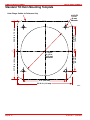
1
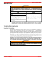
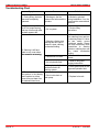
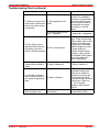
COMPACT HYDRAULIC STEERING SERVICE MANUAL NUMBER 28 STEERING SYSTEMS Section 6B - Compact Hydraulic Steering Table of Contents Important Information About Through the Transom Exhaust . . . . . . . 6B-2 Torque Specifications . . . . . . . . . . . . . . . . 6B-2 Lubricants / Sealants / Adhesives . . . . . 6B-2 Introduction . . . . . . . . . . . . . . . . . . . . . . . . . 6B-3 Through the Transom Exhaust . . . . . . . 6B-3 Removal . . . . . . . . . . . . . . . . . . . . . . . . . . . . . 6B-4 Installing The Steering Cylinder . . . . . . . 6B-6 Filling And Purging The System . . . . . . . 6B-9 Twin Station and/or Twin Cylinder . . . . . 6B-9 Single Station With Single Cylinder . . . 6B-9 Purging . . . . . . . . . . . . . . . . . . . . . . . . . . 6B-11 Connecting The Clevis . . . . . . . . . . . . . Hydraulic Fluid Level . . . . . . . . . . . . . . . Setting Fluid Level . . . . . . . . . . . . . . . . Maintaining Fluid Level . . . . . . . . . . . . System Check . . . . . . . . . . . . . . . . . . . Maintenance . . . . . . . . . . . . . . . . . . . . . . . Troubleshooting Guide . . . . . . . . . . . . . Important Information . . . . . . . . . . . . . Troubleshooting Chart . . . . . . . . . . . . . Standard Tilt Helm Mounting Template . . . . . . . . . . . . . . . . 6B-13 6B-14 6B-14 6B-14 6B-14 6B-15 6B-15 6B-15 6B-16 6B-18 6 B 90-863160--1 JUNE 2003 Page 6B-1 COMPACT HYDRAULIC STEERING SERVICE MANUAL NUMBER 28 Important Information About Through the Transom Exhaust NOTICE This hydraulic steering system is not designed for use with through the transom exhaust systems. Do not use this hydraulic steering system with a through the transom exhaust system. Torque Specifications NOTE: Securely tighten all fasteners not listed below. 1 Description Nm lb-in. Hydraulic hose end O-ring area1 15 130 Pivot bolts 34 lb-ft 25 Amount specified is MINIMUM. Do not exceed 22 Nm (200 lb-in.) Lubricants / Sealants / Adhesives WARNING Avoid serious bodily injury or death due to loss of steering control. Any non-approved fluid used in this system may cause irreparable damage, loss of steering, and cancellation of warranty. Never use brake fluid in this hydraulic steering system. Use only approved hydraulic fluids. Description Hydraulic Helm Steering Fluid Special Lubricant 101 Where Used Part Number Hydraulic hose end O-ring area Hydraulic steering system Clevis pin and clevis 92 862014Q1 92-862014Q1 92 802865A1 92-802865A1 Bushings Hydraulic Helm Steering Fluid 92-862014Q1 SeaStar Hydraulic Fluid HA5430 Chevron Aviation Fluid Mobil Aero HFA Hydraulic Steering System Obtain locallyy Shell Aero 4 Fluid meeting MIL Specification H5606C Page 6B-2 90-863160--1 JUNE 2003 COMPACT HYDRAULIC STEERING SERVICE MANUAL NUMBER 28 Introduction The system design incorporates a pressure relief valve to protect against internal fluid pressure becoming greater than individual system components are capable of sustaining without bursting or similar failure. This design minimizes the possibility of total loss of steering. The steering cylinder is referred to as an unbalanced cylinder. In any position there always remains a difference in the volume between port and starboard cylinder chambers. This is important when setting the hydraulic fluid level as outlined later. This precision built product may not function properly if dirt or contaminants are introduced into the system. CAUTION Avoid product malfunction and diminished steering control. Dirt and contamination introduced into the hydraulic system can result in damage to internal parts of steering system. Do not allow dirt or contamination to enter the helm, lines or cylinder of this steering system. IMPORTANT: Due to a small amount of internal hydraulic fluid transfer (slip), a master spoke or centered steering wheel cannot be maintained with a hydraulic steering system. For best results, use an equal distance spoke steering wheel. WARNING Avoid serious bodily injury or death due to loss of steering control. Extreme heat will lower burst pressure or melt hydraulic hoses. In either case, instant loss of steering may occur. Do not allow hydraulic hoses to contact hot engine. Through the Transom Exhaust This Compact Hydraulic Steering System is not designed for use with through the transom exhaust systems. Do not use this hydraulic steering system with a through the transom exhaust system. 90-863160--1 JUNE 2003 Page 6B-3 COMPACT HYDRAULIC STEERING SERVICE MANUAL NUMBER 28 Removal CAUTION Avoid product malfunction and diminished steering control. Dirt and contamination introduced into the hydraulic system can result in damage to internal parts of steering system. Do not allow dirt or contamination to enter the helm, lines or cylinder of this steering system. WARNING Avoid serious bodily injury or death due to loss of steering control. Extreme heat will lower burst pressure or melt steering system hydraulic hoses. Stress on hose fittings or kinks in the hose may cause hose failure. In any case , instant loss of steering may occur. Route the hydraulic hoses to avoid extreme heat, stress on hose fittings, and hose kinks. 1. Loosen hose fittings and remove hoses from steering cylinder T-fittings. 2. Plug hose ends to prevent fluid loss. c a c d b a b c d Page 6B-4 76085 - Steering cylinder - Hoses - T-fittings - Hose fittings 90-863160--1 JUNE 2003 COMPACT HYDRAULIC STEERING SERVICE MANUAL NUMBER 28 3. Remove cotter pin from port clevis pin and remove clevis pin. 4. Bend pivot bolt tab washer tabs away from bolts. 5. Remove pivot bolts. e a c a e c d c b 76087 a b c d e - Pivot bolts - Port clevis pin - Tab washer - Tab - Spacer / pivot bolt bearing 6. Remove steering cylinder from transom. 90-863160--1 JUNE 2003 Page 6B-5 COMPACT HYDRAULIC STEERING SERVICE MANUAL NUMBER 28 Installing The Steering Cylinder 1. Ensure that bushings are clean. 2. Lubricate the bushings. a A b A a 76087 a - Bushings b - Steering cylinder assembly Description A Special Lubricant 101 Where Used Part Number Bushings 92-802865A1 3. Remove upper and lower pivot bolts, spacer, and tab washers. Ensure that threads are well lubricated. Description Special Lubricant 101 Page 6B-6 Where Used Part Number Upper and lower pivot bolts threads 92-802865A1 90-863160--1 JUNE 2003 COMPACT HYDRAULIC STEERING SERVICE MANUAL NUMBER 28 4. Install steering cylinder assembly as follows: a. Position steering cylinder assembly so that upper and lower pivot bolts (with tab washers and spacers) can be threaded by hand into transom plate. b. Ensure that tab washer tangs straddle the ridge on transom plate. c. Ensure steering cylinder assembly pivots freely. d. Torque pivot bolts. Bend washer tabs against corresponding flats on bolt heads. NOTE: It may be necessary to tighten pivot bolts further to align flats on bolt with tabs on tab washer. b b f c d g e h g a d c f b 76087 a b c d e f g h 90-863160--1 JUNE 2003 - Steering cylinder assembly - Pivot bolt - Tab washer - Spacer - Tab - Transom plate - Ridge on transom plate - Tab washer tangs (straddle ridge) Description Nm Pivot bolts 34 lb-in. lb-ft 25 Page 6B-7 COMPACT HYDRAULIC STEERING SERVICE MANUAL NUMBER 28 IMPORTANT: Do not connect clevis to steering lever at this time. Bleed and purge the system before connecting clevis to steering lever. 5. Connect hoses to steering cylinder as follows: a. Apply a small amount of clean lubricant to the hydraulic hose end O-ring area. b. Push port and starboard hoses completely into fittings. c. Hand tighten hose fittings. d. Torque hose fittings. c b e d a 76085 a b c d e - Port T-fitting - Starboard T-fitting - Hose O-ring - Port hose from helm (“P”) - Starboard hose from helm (“S”) Description Hydraulic Helm Steering Fluid 1 Page 6B-8 Where Used Part Number Hydraulic hose end O-ring area 92-862014Q1 Description Nm lb-in. Steering hydraulic hose fittings1 15 130 lb-ft Amount specified is MINIMUM. Do not exceed 22 Nm (200 lb-in.) 90-863160--1 JUNE 2003 COMPACT HYDRAULIC STEERING SERVICE MANUAL NUMBER 28 Filling And Purging The System NOTE: Due to system design, one technician may not be able to completely purge all the air from the system after installation. This will result in spongy and unresponsive steering. Two technicians are required for successful filling and purging of any system. Twin Station and/or Twin Cylinder WARNING Avoid serious injury or death resulting from a loss of steering control. Improper venting or plugging of hydraulic helm pump reservoir can cause loss of fluid or introduction of air into hydraulic system resulting in insufficient hydraulic pump pressure for proper steering control. If more than one steering station is being installed, the vent/fill plug on all but the uppermost helm must be replaced with a non-vent plug which is included in a dual station fitting kit. For twin station and/or twin cylinder filling and purging (bleed) instructions, follow instructions provided by SeaStar. Refer to single station with single cylinder for instruction on how to fill and purge a single station with single cylinder system. Single Station With Single Cylinder FILLING IMPORTANT: Hydraulic fluid must be visible in the filler tube during the entire filling procedure. Do not allow the bottle of fluid used for filling to empty causing the filler tube to empty. This may introduce air into the system and cause additional filling and purging to be needed. Approximately 2 bottles (2 quarts or liters) of approved hydraulic fluid are required for this single station and single cylinder system. The length of hydraulic hoses required will cause the amount to vary. 1. Remove vent/fill plug from helm. 2. Using a Filler Kit (ordered separately), screw the filler tube into vent/fill plug hole. Hand tighten. 3. Screw bottle of hydraulic fluid into the filler tube bottle cap end. Turn bottle upside down and poke a hole in bottom of bottle. Description Hydraulic Helm Steering Fluid Where Used Part Number Hydraulic steering system 92-862014Q1 4. Ensure hydraulic fluid is always visible in filler tube and fill helm pump. Install next bottle while fluid is still visible in filler tube but first bottle is empty. 90-863160--1 JUNE 2003 Page 6B-9 COMPACT HYDRAULIC STEERING SERVICE MANUAL NUMBER 28 5. The helm is full when air bubbles no longer appear in filler tube. Stop filling. f d b a e Í Í Í Í Í Standard helm a b c d e f f d b e c c 76089 a 76089 76284 Sport helm - Helm - Vent fill plug - Filler tube - Bottle cap end - Hydraulic fluid bottle - Pin (to pierce bottle) Description Hydraulic Helm Steering Fluid Where Used Part Number Hydraulic steering system 92-862014Q1 IMPORTANT: Do not proceed to the next step until helm is full of hydraulic fluid. Ensure that no air is visible in filler tube. 6. Leave bottle of fluid connected to helm for use in purging system of air. Page 6B-10 90-863160--1 JUNE 2003 COMPACT HYDRAULIC STEERING SERVICE MANUAL NUMBER 28 Purging NOTE: Turning the steering wheel in direction shown moves the cylinder rod as indicated by arrow. a b 76090 a - Port bleeder valve b - Starboard bleeder valve 1. Remove caps from bleeder valves on T-fittings at cylinder assembly. NOTE: Place temporary hoses (obtain locally - clear hose is recommended) on bleeder outlets and position these hoses in a container to avoid spills and air returning to bleeder. 2. Turn the steering wheel slowly CLOCKWISE while your assistant opens the STARBOARD bleeder valve. 3. Continue to turn steering wheel CLOCKWISE until a stream of air-free hydraulic fluid is visible out of bleeder. b a d c c 76090 a b c d 90-863160--1 JUNE 2003 - Cap - Starboard fitting - Starboard bleeder valve - Temporary hose Page 6B-11 COMPACT HYDRAULIC STEERING SERVICE MANUAL NUMBER 28 4. While continuing to slowly turn the steering wheel, close the STARBOARD bleeder. 5. Turn steering wheel CLOCKWISE until cylinder rod is fully extended. Ensure that the steering lever does not interfere with cylinder clevis. 6. Turn the steering wheel slowly COUNTERCLOCKWISE while your assistant opens the PORT bleeder valve on the steering cylinder. 7. Continue to turn steering wheel until a stream of air-free fluid is visible out of bleeder. 8. Continuing to slowly turn the steering wheel while closing the PORT bleeder. 9. Turn the steering wheel COUNTERCLOCKWISE until the cylinder rod is fully retracted. Steering wheel will come to a stop. 10. Open STARBOARD bleeder. 11. Hold cylinder rod to prevent extension. Continue to turn steering wheel COUNTERCLOCKWISE until a stream of air-free fluid is visible out of bleeder. 12. Close the bleeder while continuing to turn steering wheel. 13. Filling and purging is complete. Refer to Hydraulic Fluid Level to set fluid level and to check the system after connecting the clevis. b c a b 76090 a - Starboard T-fitting b - Starboard bleeder valve c - Cap Page 6B-12 90-863160--1 JUNE 2003 COMPACT HYDRAULIC STEERING SERVICE MANUAL NUMBER 28 Connecting The Clevis 1. Lubricate clevis pin and clevis. Description Special Lubricant 101 Where Used Part Number Clevis pin and clevis 92-802865A1 2. Connect clevis to steering lever. Spread both ends of cotter pin. IMPORTANT: Ensure that the clevis is positioned as shown below. The angled notch in the clevis must face the rear. a b b c c 76087 a - Clevis b - Clevis pin and cotter pin c - Steering lever 90-863160--1 JUNE 2003 Page 6B-13 COMPACT HYDRAULIC STEERING SERVICE MANUAL NUMBER 28 Hydraulic Fluid Level WARNING Avoid serious bodily injury or death due to loss of steering control. This system operates with an unbalanced steering cylinder volume. Proper fluid level in the helm can only be set or checked with the cylinder rod fully retracted. Do not set or check hydraulic fluid level in helm with cylinder rod extended. Setting Fluid Level System must be filled and purged as outlined previously before setting fluid level. 1. Ensure cylinder rod is fully retracted. 2. With filler tube screwed into helm filler plug hole, fill tube approximately 1/2 full of air-free fluid. 3. Open starboard bleeder valve and slowly turn steering wheel CLOCKWISE until fluid level in filler tube is at the top of the plastic filler fitting. Continue turning steering wheel CLOCKWISE 1/4 turn more and stop. Close bleeder. 4. Remove filler tube. Fluid level should be at bottom of filler hole. Install vent/fill plug. Maintaining Fluid Level To maintain proper fluid level, observe the following: • Do not allow fluid level to drop more than 6 mm (1/4 in.) below bottom of filler hole. • Check fluid level periodically. System Check The system must be checked for proper connections, possible leaks, and complete purging of air after filling, purging, and setting the fluid level. IMPORTANT: In the following, turn the wheel with enough force to exceed the pressure relief valve in the helm. This should not harm the helm or the system. 1. Turn steering wheel (any wheel on multi-steering station) very hard to port to pressurize system. 2. While pressure is maintained, check all port fittings and hose connections. Ensure that there are no leaks. If leaks are present, correct before using. 3. Turn steering wheel (any wheel on multi-steering station) very hard to starboard to pressurize system. 4. While pressure is maintained, check all starboard fittings and hose connections. Ensure that there are no leaks. If leaks are present, correct before using. NOTE: Observing a significant drop in the fluid level at the helm while performing the system check may mean you are compressing air and further filling and purging would be required. 5. If no leaks are present, the system is ready for service. Page 6B-14 90-863160--1 JUNE 2003 COMPACT HYDRAULIC STEERING SERVICE MANUAL NUMBER 28 Maintenance WARNING Avoid serious bodily injury or death due to loss of steering control. Failure to comply with maintenance checks may result in a loss of hydraulic pressure due to insufficient hydraulic fluid, or proper mechanical function necessary for steering control. Task Interval Check the hydraulic fluid level in the helm pump. Check for leaks. Check mechanical linkages and connections. Tighten loose parts and replace badly worn parts. A minimum of two times a year, or at the first sign or indication that the steering system is not operating normally or correctly; whichever occurs first. Check cylinder shaft for nicks and scratches.2 2 A damaged cylinder shaft can cause seal failure and leaks. Replacing seals on a damaged cylinder assembly will not stop leaks. A damaged cylinder shaft must be replaced immediately. Troubleshooting Guide Important Information Whenever a troubleshooting solution calls for removal from vessel and/or dismantling of steering system components, such work must be carried out by a qualified marine mechanic. The following is offered as a guide only and neither Mercury MerCruiser nor the helm manufacturer are responsible for any consequences resulting from incorrect repairs. Most faults occur when the installation instructions are not followed and usually show up immediately upon filling the system. The following trouble shooting chart provides the most common faults encountered and their likely cause and solution. Sometimes when returning the steering wheel from a hard-over position, a slight resistance may be felt and a clicking noise may be heard. This should not be mistaken as a fault, as it is a completely normal situation caused by the releasing of the lockspool in the system. WARNING Avoid serious injury or death due to FIRE or EXPLOSION. Ensure that engine compartment is well ventilated and that no gasoline vapors are present to prevent the possibility of a FIRE or EXPLOSION. 90-863160--1 JUNE 2003 Page 6B-15 COMPACT HYDRAULIC STEERING SERVICE MANUAL NUMBER 28 Troubleshooting Chart Symptom Cause Solution 1. During filling, the helm becomes completely jammed. A. Blockage in the line between the helms and the cylinders. A. Ensure that hoses were not kinked or pinched during installation. If so, the hose must be removed and replaced. 2. System is very difficult to fill. Air keeps burping out top of helm even after system appears full. A. Air in system. A. Review filling instructions. A. Steering cylinder pivot bushings are too tight or trunnion is bent, causing mechanical binding. A. To test, disconnect clevis from steering lever and turn the steering wheel. If it does not turn easily, correct mentioned causes. Please note that excessively loose connections to steering cylinder or steering lever can also cause mechanical binding. B. Restrictions in hoses. B. Find restrictions and correct. C. Air in hydraulic fluid. C. Refer to filling and purging instructions. D. Wrong hydraulic fluid has been used to fill steering system. D. Drain system and fill with approved hydraulic fluid. 3. Steering is stiff and hard to turn, even when the vessel is not moving. moving 4.The helm unit, or one in the system, is very bumpy A. Dirt in inlet check of and requires too many helm pump. turns from port hard-over to starboard hard-over. Page 6B-16 A. Replace helm unit. 90-863160--1 JUNE 2003 COMPACT HYDRAULIC STEERING SERVICE MANUAL NUMBER 28 Troubleshooting Chart (continued) Symptom Cause Solution A. Steering wheel is too small. A. Fit larger wheel if possible, see installation instructions. If the problem cannot be rectified by the above mentioned solution, proceed with next cause and solution or consult factory. B. Incorrect setting of trim tabs, if equipped. B. Adjust tabs, if equipped. 6. Drive drifts to port or starboard while vessel is underway, even when wheel is not being turned. A. Dirt in check valves. A. Remove check valve plugs. These are the larger plugs on either side on rear of helm. Clean ball seats and balls and reassemble. Note: Be prepared to lose a certain amount of hydraulic fluid during this procedure. Have a small can available. Refill system when check balls have been re-assembled. 7. Turning one wheel causes second wheel to rotate. A. Refer to Number 6. A. Refer to Number 6. 8. Seals will sometimes leak if steering system is not vented at uppermost helm. A. Refer to Solution. A. The helm has a field replaceable wheel shaft seal that can readily be replaced by removing the steering wheel and seal cover held in place by three small screws. Quad ring No. 210 is found in Seastar Helm Seal Kit HS5151. 9. Vent/fill plug leaks when turning to port. A. Cylinder rod extended during filling. A. Ensure cylinder rod is retracted during filling. 5. Steering is easy to turn at the dock, but becomes hard to turn when vessel is underway. 90-863160--1 JUNE 2003 Page 6B-17 COMPACT HYDRAULIC STEERING SERVICE MANUAL NUMBER 28 Standard Tilt Helm Mounting Template Helm Flange Outline for Reference Only 2-3/16 in. (56 mm) 1 HOLE 4-1/2 in. (115 mm) Diameter 1-13/16 in. (46 mm) 2-17/32 in. (64 mm) 2-25/32 in. 70 mm) TOP 4 HOLES 5/16 in. (8 mm) Diameter 4 in. (102 mm) 5-5/32 in. (131 mm) 79260 Page 6B-18 90-863160--1 JUNE 2003