1
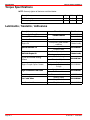
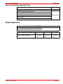
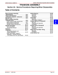
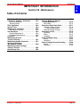
MAINTENANCE SERVICE MANUAL NUMBER 28 IMPORTANT INFORMATION 1 Section 1B - Maintenance B Table of Contents Torque Specifications . . . . . . . . . . . . . . . . Lubricants / Sealants / Adhesives . . . . . Approved Hydraulic Steering Fluids . . . . . . . . . . . . . . . . . . . . Fluid Capacities . . . . . . . . . . . . . . . . . . . . . . Special Tools . . . . . . . . . . . . . . . . . . . . . . . . Maintenance Schedules . . . . . . . . . . . . . . Maintenance Intervals . . . . . . . . . . . . . . . Gas Sterndrive . . . . . . . . . . . . . . . . . . . . . . . Routine Maintenance . . . . . . . . . . . . . . . Scheduled Maintenance . . . . . . . . . . . . Corrosion . . . . . . . . . . . . . . . . . . . . . . . . . . . Maintaining Ground Circuit Continuity . . . . . . . . . . . . . . . . . . . . Maintaining Anodic Protection . . . . . . . . Checking Quicksilver MerCathode System . . . . . . . . . . . . . . . . . Maintaining Power Package Exterior Surfaces . . . . . . . . . . . . . . . . . . . . Boat Bottom Care . . . . . . . . . . . . . . . . . . . . 90-863160--1 JUNE 2003 1B-2 1B-2 1B-3 1B-3 1B-4 1B-5 1B-5 1B-5 1B-5 1B-6 1B-7 1B-7 1B-7 1B-8 Anti-fouling Paint . . . . . . . . . . . . . . . . . . . . 1B-9 Steering Head and Remote Control Maintenance . . . . . . . . . . . . . . . . 1B-10 Shift Cable . . . . . . . . . . . . . . . . . . . . . . . . 1B-10 Sterndrive Water Drain Holes . . . . . . . . 1B-11 Sterndrive Water Pickups . . . . . . . . . . . 1B-12 Flushing Attachments . . . . . . . . . . . . 1B-13 Alternative Water Pickups . . . . . . . . . . . 1B-16 Sterndrive Unit Oil . . . . . . . . . . . . . . . . . . 1B-18 Checking . . . . . . . . . . . . . . . . . . . . . . . . . 1B-18 Filling . . . . . . . . . . . . . . . . . . . . . . . . . . . . 1B-19 Changing . . . . . . . . . . . . . . . . . . . . . . . . . 1B-20 Power Package Layup . . . . . . . . . . . . . . . 1B-22 Engine . . . . . . . . . . . . . . . . . . . . . . . . . . . 1B-22 Sterndrive . . . . . . . . . . . . . . . . . . . . . . . . 1B-22 Power Package Recommissioning . . . 1B-28 Engine . . . . . . . . . . . . . . . . . . . . . . . . . . . 1B-28 Sterndrive . . . . . . . . . . . . . . . . . . . . . . . . 1B-28 1B-8 1B-8 Page 1B-1 SERVICE MANUAL NUMBER 28 MAINTENANCE Torque Specifications NOTE: Securely tighten all fasteners not listed below. Description Nm lb-in. Oil fill/drain plug 4.5 40 Oil vent plug 4.5 40 lb-ft Lubricants / Sealants / Adhesives Description Mercury Light Gray Primer Mercury Phantom Black Corrosion Guard Engine Oil Special Lubricant 101 SAE 30W Engine Oil U joint And Gimbal Bearing U-joint Grease Where Used Part Number 92-802878 52 Painted surfaces 92-802878Q 1 Painted surfaces 92-802878-55 Pivot points, guide contact surfaces Obtain locally Steering cable 92 802865A1 92-802865A1 Propeller shaft Tie bar pivot points Steering system pivot points Gimbal bearing Obtain locally 92 802870A1 92-802870A1 Drive shaft U-joints Coupler Engine Coupler Spline Grease High Performance Gear Lube Liquid Neoprene 2 4 C with Teflon 2-4-C Anti-Corrosion Grease Page 1B-2 U-joint shaft splines and O-rings Gear lube monitor 92 802854A1 92-802854A1 To fill sterndrive Clamps and terminals Steering cable Propeller shaft Propeller shaft 92-802869A1 92-25711-3 92 802859A1 92-802859A1 92-802867A1 90-863160--1 JUNE 2003 MAINTENANCE SERVICE MANUAL NUMBER 28 Approved Hydraulic Steering Fluids Description Part Number Hydraulic Helm Steering Fluid 92-862014A1 SeaStar Hydraulic Fluid HA5430 Chevron Aviation Fluid Mobil Aero HFA Obtain locallyy Shell Aero 4 Hydraulic Fluid meeting MIL Specification H5606C Fluid Capacities NOTICE Unit Of Measurement: Milliliters (Fluid Ounces) All capacities are approximate fluid measures. Model Sterndrive unit oil capacity 90-863160--1 JUNE 2003 Bravo One Bravo Two Bravo Three 2602 ml. (88 fl oz) 3076 ml. (104 fl oz) 2839 ml. (96 fl oz) Page 1B-3 SERVICE MANUAL NUMBER 28 MAINTENANCE Special Tools Dual Water Pick-Up Flush Gear Case Seal Kit Use to block-off the front water inlet holes on the dual water inlet gear cases. 91-881150Q1 Attaches to the sterndrive unit water intakes; provides a fresh water connection when flushing the cooling system or operating the engine. 91-44357Q2 Use for flushing sterndrives with low water inlet gear cases. 91-84996T1 Senses an electrical current in the water when testing the MerCathode system. Use to check hull potential. 91-76675T1 77977 Flushing Device 73440 Flushing Kit 78135 Reference Electrode 73446 Page 1B-4 90-863160--1 JUNE 2003 MAINTENANCE SERVICE MANUAL NUMBER 28 Maintenance Schedules Maintenance Intervals Maintenance intervals and the corresponding tasks to be performed, as shown in this current schedule or as found in a previously printed schedule, are generally based on an average boating application and environment. However, individual operating habits and personal maintenance preferences can have an impact on the suggested intervals. In consideration of these factors, Mercury MerCruiser has adjusted some maintenance intervals and the corresponding tasks to be performed. In some cases, this may allow for more individual tasks in a single visit to the servicing dealer. Therefore, it is very important that the boat owner and the servicing dealer discuss the current Maintenance Schedule and develop appropriate maintenance intervals to coincide with the individual operating habits, the environment and the maintenance requirements. CAUTION Always disconnect battery cables from battery BEFORE working around electrical systems components to prevent injury to yourself and damage to electrical system should a wire be accidentally shorted. Gas Sterndrive Routine Maintenance * Each Day Start Each Day End Weekly Check sterndrive unit oil level, trim pump oil level and steering fluid level. Check water pickups for debris or marine growth. Check water strainer and clean. Check coolant level. Inspect sterndrive unit anodes and replace if 50 percent eroded. Lubricate propeller shaft and the retorque nut (if operating in only freshwater, this maintenance may be extended to every four months). Every Two Months * Only perform maintenance that applies to your particular power package Standard models Horizon models 90-863160--1 JUNE 2003 Page 1B-5 SERVICE MANUAL NUMBER 28 MAINTENANCE Gas Sterndrive (continued) Scheduled Maintenance * Every Every Every 200 300 Every Every 100 Annu2 5 hours hours hours or ally or 3 or 3 years years Annually years years Touch-up power package paint and spray with Corrosion Guard. Change sterndrive unit oil and retorque connection of gimbal ring to steering shaft. Check steering system and remote control for loose, missing or damaged parts. Lubricate cables and linkages. Inspect U-joints, splines and bellows. Check clamps. Check engine alignment. Lubricate U-joints splines. Lubricate gimbal bearing and engine coupler. Check continuity circuit for loose or damaged connections. Test MerCathode unit output on Bravo Models. * Only perform maintenance that applies to your particular power package Standard models Horizon models Lubricate engine coupler every 50 hours if operated at idle for prolonged periods of time or if used in heavy boat applications. Page 1B-6 Later standard-models can be serviced every 200 hours or 3 years. 90-863160--1 JUNE 2003 MAINTENANCE SERVICE MANUAL NUMBER 28 Corrosion Refer to the Mercury Precision Parts / Marine Corrosion Protection Guide (90-881813003). Maintaining Ground Circuit Continuity The transom assembly and sterndrive unit are equipped with a ground wire circuit to ensure good electrical continuity between engine, transom assembly and sterndrive components. Good continuity is essential for the MerCathode System to function effectively. Refer to Section 7. Maintaining Anodic Protection Each sterndrive unit is equipped with a sacrificial anodic plate to help protect underwater metal parts from galvanic corrosion. Because of its self-sacrificing nature, anodic plate MUST BE replaced if eroded 50% or more. Refer to Section 7. IMPORTANT: Replace sacrificial anodes if eroded 50 percent or more. 1 2 73919 3 70578 71966 4 5 6 72032 Common sacrificial anodes and MerCathode system 1 - Universal anodic plate 2 - Anodic plate 3 - MerCathode system 4 - Anode kit (if equipped) 5 - Trim cylinder anodes 6 - Bearing carrier anode (Bravo One) Universal Anodic Plate - serves as a sacrificial anode. Anodic Plate - serves as a sacrificial anode. MerCathode System - standard on Bravo. Anode Kit (if equipped) - mounted to boat transom. Acts as a sacrificial anode. Trim Cylinder Anodes - mounted on each trim cylinder. Bearing Carrier Anode (Bravo One) - located in front of the propeller, between the front side of the propeller and the gear housing. 90-863160--1 JUNE 2003 Page 1B-7 SERVICE MANUAL NUMBER 28 MAINTENANCE Checking Quicksilver MerCathode System The MerCathode system should be tested to ensure adequate output. The test should be performed where boat is moored, using the Reference Electrode and Test Meter. Refer to Section 7. Reference Electrode Senses an electrical current in the water when testing the MerCathode system. Use to check hull potential. 91-76675T1 73446 Maintaining Power Package Exterior Surfaces 1. Spray entire power package at recommended intervals with Corrosion Guard. Follow instructions on can for proper application. Description Corrosion Guard Where Used Part Number Painted surfaces 92-802878-55 2. Clean entire power package. External surfaces that have become bare should be repainted with Primer and Spray Paint at recommended intervals. Description Mercury Light Gray Primer Mercury Phantom Black Where Used Painted surfaces Part Number 92-802878 52 92-802878Q 1 Boat Bottom Care To achieve maximum performance and fuel economy, boat bottom MUST BE kept clean. Accumulation of marine growth or other foreign matter can greatly reduce boat speed and increase fuel consumption. To ensure best performance and efficiency, periodically clean boat bottom in accordance with manufacturer’s recommendations. In some areas, it may be advisable to paint the bottom to help prevent marine growth. Refer to the following information for special notes about the use of anti-fouling paints. Page 1B-8 90-863160--1 JUNE 2003 MAINTENANCE SERVICE MANUAL NUMBER 28 Anti-fouling Paint IMPORTANT: Corrosion damage that results from the improper application of anti-fouling paint will not be covered by the limited warranty. Painting Boat Hull or Boat Transom: Anti-fouling paint may be applied to boat hull and boat transom but you must observe the following precautions: IMPORTANT: Do not paint anodes or MerCathode System reference electrode and anode, as this will render them ineffective as galvanic corrosion inhibitors. IMPORTANT: If anti-fouling protection is required for boat hull or boat transom, copper base paints, if not prohibited by law, can be used. If using copper based anti-fouling paints, observe the following: • Avoid an electrical interconnection between the Mercury MerCruiser product, anodic blocks, or MerCathode system and the paint by allowing a minimum of 40 mm (1-1/2 in.) UNPAINTED area on transom of the boat around these items. a b 71176 a - Painted boat transom b - Minimum 40 mm (1-1/2 in.) UNPAINTED area around transom assembly NOTE: Sterndrive unit and transom assembly can be painted with a good quality marine paint or an anti-fouling paint that does not contain copper or any other material that could conduct electrical current. Do not paint drain holes, anodes, MerCathode system, and items specified by boat manufacturer. 90-863160--1 JUNE 2003 Page 1B-9 SERVICE MANUAL NUMBER 28 MAINTENANCE Steering Head and Remote Control Maintenance 1. Lubricate steering head and remote control at recommended intervals. Inspect steering head and remote control for ease of operation. Description Engine Oil Where Used Part Number Pivot points, guide contact surfaces Obtain locally Shift Cable 1. Lubricate the pivot points and the guide contact surfaces. b a b a a 79178 Typical a - Pivot points b - Guide contact surfaces Description Engine Oil Page 1B-10 Where Used Part Number Pivot points, guide contact surfaces Obtain locally 90-863160--1 JUNE 2003 MAINTENANCE SERVICE MANUAL NUMBER 28 Sterndrive Water Drain Holes 1. Using a piece of wire, check water drain holes in sterndrive unit to ensure that they are open. b d e c a 70134 78525 Sterndrive unit water drain holes a - Speedometer pitot tube b - Anode cavity vent hole c - Anode cavity drain passage d - Gear housing water drain hole (1 each - port and starboard) e - Gear housing cavity vent hole (Bravo II only) 90-863160--1 JUNE 2003 Page 1B-11 SERVICE MANUAL NUMBER 28 MAINTENANCE Sterndrive Water Pickups IMPORTANT: Bravo models equipped with closed cooling require dual water pickups and must be equipped with a through the hull or through the transom pickup in addition to the sterndrive water inlets. There are 3 types of water pickups available on Mercury MerCruiser sterndrives: low water, dual water, and side pickups. Dual water pickups require the Flushing Device (92-44357Q2) and the Dual Water Pick-Up Flush Gear Case Seal Kit (92-881150Q1), low water pickups require the Flushing Kit (92-849996T1), and side pickups require the Flushing Device (92-44357Q2). 77899 Dual water pickup Page 1B-12 Low water pickup Side pickup 90-863160--1 JUNE 2003 MAINTENANCE SERVICE MANUAL NUMBER 28 FLUSHING ATTACHMENTS Dual Water Pick-Up Flush Gear Case Seal Kit Use to block-off the front water inlet holes on the dual water inlet gear cases. 91-881150Q1 Attaches to the sterndrive unit water intakes; provides a fresh water connection when flushing the cooling system or operating the engine. 91-44357Q2 Use for flushing sterndrives with low water inlet gear cases. 91-84996T1 77977 Flushing Device 73440 Flushing Kit 78135 90-863160--1 JUNE 2003 Page 1B-13 SERVICE MANUAL NUMBER 28 MAINTENANCE 0194.2 NOTE: Flushing is needed only for salty, brackish, mineral laden or polluted water applications. Flushing is recommended after each outing for best results. CAUTION If flushing with the boat in the water, seawater can flow into the engine causing engine damage. Water inlet must be closed when flushing the engine. 1. Drain the seawater section of the cooling system. 2. Seawater cooled Models: Proceed to Step 4. or Step 5. 3. Closed Cooled models could require a through the hull or through the transom water inlet and sterndrive water inlets. Verify your model as follows: a. If you have a Bravo sterndrive unit and closed cooling (equipped with a heat exchanger on the front of the engine), verify that a hose is connected between the transom and the y-fitting and between the sea strainer and the y-fitting. b. If there is a hose running to the transom, shut the seacock located in the hose between the sea strainer and the y-fitting. Proceed to Step 4. or Step 5. c. If there is not a hose running to the transom, refer to Alternative Water Pickups. 4. If flushing the cooling system with boat in water: a. Raise sterndrive unit to TRAILER position. b. Install appropriate flushing attachments over water intake openings in the gear housing. c. Lower sterndrive unit to full DOWN/IN position. 5. If flushing cooling system with boat out of water: a. Lower sterndrive unit to full DOWN/IN position. WARNING Contact with moving drive components and the propeller can cause personal injury or death. To avoid possible injury , remove the propeller and ensure that no people or animals are in the area of the drive unit while flushing. b. Remove propeller. c. Install appropriate flushing attachments over water intlets in gear housing. 6. Connect hose between flushing attachment and water source. 7. With sterndrive unit in normal operating position, partially open water source (about 1/2 maximum). Page 1B-14 90-863160--1 JUNE 2003 MAINTENANCE SERVICE MANUAL NUMBER 28 8. Place sterndrive in NEUTRAL, idle speed position and start engine. CAUTION Suction created by the seawater pickup pump may collapse the flushing water hose causing the engine to overheat. Avoid engine damage from overheating, Do NOT operate the engine above 1500 rpm. 9. Slowly advance throttle until engine reaches 1300 rpm (+/–100 rpm). CAUTION Engine overheating can cause engine damage. To avoid, observe the water temperature gauge and ensure that the engine is operating in the normal range. 10. Observe the water temperature gauge to ensure that the engine is operating in the normal range. 11. Operate engine with sterndrive in NEUTRAL for about 10 minutes or until discharge water is clear. 12. Slowly return throttle to idle speed position. 13. Stop engine. 14. Shut off water and remove flushing attachment. 15. Remove the seawater inlet hose from the seawater pump and plug the hose to prevent water from siphoning into the engine. 16. Tag the ignition switch with an appropriate tag requiring the seawater inlet hose to be reconnected prior to operating engine. 90-863160--1 JUNE 2003 Page 1B-15 SERVICE MANUAL NUMBER 28 MAINTENANCE 0195.2 Alternative Water Pickups IMPORTANT: Two water sources are needed for this procedure. NOTE: Flushing is needed only for salty, brackish, mineral laden or polluted water applications. Flushing is recommended after each outing for best results. 1. Drain the seawater section of the cooling system. IMPORTANT: Engines with the sterndrive water inlet blocked off at the gimbal housing and using a through the hull water inlet need a supply of cooling water available to both the sterndrive unit and to the engine during operation. 2. If flushing cooling system with boat in water: a. Raise sterndrive unit to TRAILER position. b. Install appropriate flushing attachment over the water intake openings in the gear housing. c. Lower sterndrive unit to full DOWN/IN position. d. Proceed to Step 4. 3. If flushing cooling system with boat out of water: a. Lower sterndrive unit to full DOWN/IN position. WARNING Contact with moving drive components and the propeller can cause personal injury or death. To avoid possible injury , remove the propeller and ensure that no people or animals are in the area of the drive unit while flushing. b. Remove propeller. c. Install appropriate flushing attachments over water inlets gear housing. 4. Connect hose between flushing attachment and water source. 5. Disconnect the water inlet hose (upper hose) from the aft side of the seawater pump. 77945 6. Plug the seawater inlet hose or close the seacock to prevent water from siphoning into the boat. Page 1B-16 90-863160--1 JUNE 2003 MAINTENANCE SERVICE MANUAL NUMBER 28 7. Using a suitable adapter, connect the flushing hose from the water source to the water inlet of the seawater pump. CAUTION Overheating from insufficient cooling water will cause engine and drive system damage. Ensure that there is sufficient water always available at water inlet holes during operation. 8. With sterndrive unit in normal operating position, partially open the 2 water sources (about 1/2 maximum). 9. Place sterndrive in NEUTRAL, idle speed position and start engine. CAUTION Suction created by the seawater pickup pump may collapse the flushing water hose causing the engine to overheat. Avoid engine damage from overheating, Do NOT operate the engine above 1500 rpm. 10. Slowly advance throttle until engine reaches 1300 rpm (+/–100 rpm). CAUTION Engine overheating can cause engine damage. To avoid, observe the water temperature gauge and ensure that the engine is operating in the normal range. 11. Observe the water temperature gauge to ensure that the engine is operating in the normal range. 12. Operate engine with sterndrive in NEUTRAL for about 10 minutes or until discharge water is clear. 13. Slowly return throttle to idle speed position. 14. Stop engine. 15. Shut off water and remove flushing attachments. 16. If the boat is out of the water: Install the water inlet hose to the aft side of the seawater pump. Tighten the hose clamp securely. 17. If the boat is in the water: Tag the ignition switch with an appropriate tag requiring the seawater inlet hose to be reconnected prior to operating engine. 90-863160--1 JUNE 2003 Page 1B-17 SERVICE MANUAL NUMBER 28 MAINTENANCE Sterndrive Unit Oil Checking 1. Periodically inspect oil for water to ensure that sterndrive unit seals are not leaking. 2. Check for water at bottom of gear lube monitor. If a water leak is indicated, the sterndrive unit must be resealed. IMPORTANT: If sterndrive unit has set overnight or longer, check for water in sterndrive unit. a. Bravo I: Trim sterndrive unit to full DOWN/IN position. a b 70023 a - Oil fill/drain plug b - Sealing washer b. Bravo II and III: Trim sterndrive unit to full UP/OUT position. b 22103 a 22101 a - Oil fill/drain plug b - Sealing washer c. Remove fill/drain plug. If water runs out, sterndrive unit is leaking and must be resealed. d. Reinstall fill/drain plug and torque. Page 1B-18 Description Nm lb-in. Fill/drain plug 4.5 40 lb-ft 90-863160--1 JUNE 2003 MAINTENANCE SERVICE MANUAL NUMBER 28 Filling IMPORTANT: Position sterndrive unit in DOWN/IN position so that anti-ventilation plate is level. CAUTION If more than 59 ml (2 fl oz) of oil is required to fill sterndrive unit, an oil leak may exist. Find and correct cause of leak before unit is placed in operation. NOTE: Sterndrive unit oil level is checked at gear lube monitor. IMPORTANT: Oil level in gear lube monitor will rise and fall during sterndrive operation; always check oil level when sterndrive is cool and engine is shut down. NOTE: Oil will purge from gear lube monitor if rubber gasket is not in cap. a 77813 a - Gear lube monitor full line / operating range 1. Fill gear lube monitor to FULL line / OPERATING range 2. Ensure that rubber gasket is installed in gear lube monitor cap. 3. Install gear lube monitor cap. Tighten cap 1/4 turn after monitor contacts gasket. IMPORTANT: Do not overtighten cap. 4. Check oil level in gear lube monitor. 90-863160--1 JUNE 2003 Page 1B-19 SERVICE MANUAL NUMBER 28 MAINTENANCE Changing 1. Remove the gear lube monitor from the bracket. a 77813 a - Gear lube monitor 2. Empty the contents into a suitable container. 3. Install the monitor in the bracket. 4. Bravo One Models: Remove the propeller, place the sterndrive unit in full trim limit IN position, remove the oil fill/drain screw and sealing washer and drain the oil. a 70568 b a - Oil fill/drain b - Sealing washer 5. All Other Models: Place the sterndrive unit in full trim limit OUT position, remove the oil fill/drain screw and sealing washer and drain the oil. b a 72522 a - Oil fill/drain b - Sealing washer Page 1B-20 90-863160--1 JUNE 2003 MAINTENANCE SERVICE MANUAL NUMBER 28 6. Remove the oil vent screw and sealing washer. Allow the oil to drain completely. b a 77106 a - Oil vent screw b - Sealing washer IMPORTANT: If any water drained from the oil fill/drain hole, or if the oil appears milky, the sterndrive unit is leaking and should be checked immediately by your authorized Mercury MerCruiser dealer. 7. Lower the sterndrive unit so that the propeller shaft is level. Fill the sterndrive unit through the oil fill/drain hole, with specified gear lube until an air-free stream of lubricant flows from oil vent hole. Where Used Part Number Gear lube monitor 92-802854A1 Description High Performance Gear Lube IMPORTANT: Use only High Performance Gear Lube in sterndrive unit. 8. Install the oil vent screw and sealing washer. 9. Continue to pump gear lube into the gear lube monitor circuit until the gear lube appears in the gear lube monitor. 10. Fill the monitor so that the oil level is in the operating range. Do not overfill. Ensure that the rubber gasket is inside the cap and install. Do not overtighten. Description High Performance Gear Lube Where Used Part Number Gear lube monitor 92-802854A1 11. Remove the pump from the oil fill/drain hole. Quickly install the sealing washer and oil fill/drain screw. Tighten securely. 12. Reinstall the propeller. 13. Recheck the oil level after the first use. IMPORTANT: Oil level in the gear lube monitor will rise and fall during sterndrive operation; always check the oil level when the sterndrive is cool and the engine is shut down. 90-863160--1 JUNE 2003 Page 1B-21 SERVICE MANUAL NUMBER 28 MAINTENANCE Power Package Layup Engine Refer to appropriate Mercury MerCruiser Engine Service Manual. Sterndrive 1. Lubricate the steering system. WARNING Do not grease steering cable while extended. Hydraulic lock could occur and cause loss of steering control. a. If steering cable has grease fittings: Turn steering wheel until steering cable is fully retracted into cable housing. Apply approximately 3 pumps of grease from a typical hand-operated grease gun. NOTE: If steering cable does not have grease fitting, inner wire of cable cannot be greased. A a 71903 a - Steering cable grease fitting Description A Special Lubricant 101 Where Used Part Number Steering cable 92-802865A1 b. Turn steering wheel until steering cable is fully extended. Lightly lubricate the exposed part of cable. a A 71901 a - Extended steering cable Description A Special Lubricant 101 Page 1B-22 Where Used Part Number Steering cable 92-802865A1 90-863160--1 JUNE 2003 MAINTENANCE SERVICE MANUAL NUMBER 28 c. Lubricate the steering system pivot points. A a 71904 a - Steering system pivot points Description A SAE 30W Engine Oil Where Used Part Number Steering system pivot points Obtain locally d. On dual engine boats: Lubricate the tie bar pivot points. Description SAE 30W Engine Oil Where Used Part Number Tie bar pivot points Obtain locally e. Upon first starting engine, turn steering wheel several times to starboard and then port to ensure that the steering system operates properly before getting underway. 2. Lubricate the gimbal bearing and the sterndrive propeller shaft. a. Lubricate gimbal bearing by applying approximately 8-10 pumps of grease from a typical hand-operated grease gun. a A 77068 a - Gimbal bearing grease fitting Description A 90-863160--1 JUNE 2003 U-joint And Gimbal Bearing Grease Where Used Part Number Gimbal bearing 92-802870A1 Page 1B-23 SERVICE MANUAL NUMBER 28 MAINTENANCE b. Apply a liberal coat of one of the following lubricants to the propeller shaft. a A a A 77046 72239 a - Propeller shaft Description Where Used Part Number Anti-Corrosion Grease 92-802867A1 Special Lubricant 101 92-802865A1 Propeller p shaft 2-4-C with Teflon 92-802859A1 3. Lubricate engine coupler splines through grease fittings on coupler by applying approximately 8-10 pumps of grease from a typical hand-operated grease gun. NOTE: If equipped with a sealed engine coupler, the sealed coupler and shaft splines can be lubricated without removing the sterndrive unit. Apply lubricant from a typical hand-operated grease gun. NOTE: If the boat is operated at idle for prolonged periods of time or if used in heavy boat applications, Bravo model aluminum coupler should be lubricated every 50 hours. 79177 a Steel Coupler a Aluminum Coupler a - Engine coupler grease fitting Description Engine Coupler Spline Grease Page 1B-24 Where Used Part Number Coupler 92-802869A1 90-863160--1 JUNE 2003 MAINTENANCE SERVICE MANUAL NUMBER 28 a. Drive shaft extension models: Lubricate the drive shaft grease fittings at transom end by applying approximately 10-12 pumps of grease from a typical hand-operated grease gun. A a 71346 a - Grease fitting locations Description A U-joint and Gimbal Bearing Grease Where Used Part Number Drive shaft U-joints 92-802870A1 b. Lubricate drive shaft grease fittings at engine end by applying approximately 3-4 pumps of grease from a typical hand-operated grease gun. a A 71347 a - Grease fitting locations Description A 90-863160--1 JUNE 2003 U-joint and Gimbal Bearing Grease Where Used Part Number Drive shaft U-joints 92-802870A1 Page 1B-25 SERVICE MANUAL NUMBER 28 MAINTENANCE 4. Lubricate the sterndrive U-joint cross bearings by applying approximately 3-6 pumps of grease from a typical hand-operated grease gun. NOTE: The crosses and bearings on the sterndrive U-joint will need to be lubricated through the grease fittings. Apply lubricant from a typical hand-operated grease gun until a small amount of grease begins to push out. The sterndrive unit must be removed to grease these fittings. 5. Lubricate the U-joint shaft splines and the O-rings. d b a A A c c A 76832 22026 a b c d A - U-joint shaft splines - U-joint shaft O-rings - Cross bearings grease insert - Cross bearings assemblies Description A Engine Coupler Spline Grease Where Used Part Number U-joint shaft splines and O-rings 92-802869A1 92 802869A1 Cross bearings grease insert Page 1B-26 90-863160--1 JUNE 2003 MAINTENANCE SERVICE MANUAL NUMBER 28 6. Inspect U-joint bellows for cracks or other signs of deterioration. Check bellows clamps for tightness. a. Rotate the bell housing in the upward and side to side directions to inspect bellows and hose clamps. e c a b d a b c d e 76620 - U-joint bellow - Exhaust bellow - Bell housing - Gimbal ring - Gimbal housing 7. Check engine alignment. Refer to appropriate Mercury MerCruiser Engine Service Manual. 90-863160--1 JUNE 2003 Page 1B-27 SERVICE MANUAL NUMBER 28 MAINTENANCE Power Package Recommissioning Engine Refer to appropriate Mercury MerCruiser Engine Service Manual. Sterndrive 1. Perform ALL maintenance specified for completion annually in Maintenance Chart except items which were performed at the time of sterndrive layup. 2. Apply a thin coat of petroleum based grease to clamps and terminals to help retard corrosion. Description Liquid Neoprene Where Used Part Number Clamps and terminals 92-25711-3 3. After recommissioning and starting engine, check steering system and shift control for proper operation. 4. Check all fluid levels before and after first use. Page 1B-28 90-863160--1 JUNE 2003