1
(DrrroNEER'
ORDERNO.
ART- 620-0
NON
SWITCHING
AMP
S T E R E OA M P L I F I E R
AS FoLLoWS:
MoDELA-5coMEslN S|XVERs|oNsD|ST|NGU|SHED
Remarks
Voltage
Type
U.S.A. model
KU
120V onlY
s
(Switchablel
1lOV, 12OV, 22OV and 24OV
KC
120V onlY
YP
240V onlY
HE
22OV and 240V (Switchablel
Europe model
HB
22OY and 240V (Switchable)
United Kingdom model
G e n e r a le x p o r t m o d e l
Canada model
Australiamodel
repairingthe HE' HB types' pelaseseethe
This servicemanual is applicableto the KU type' Whgn
for S, YP and KC types'
additionalservicemanualiÀnf-OZf ), and seethe ART'622
modelA'6 servicemanual(ART'762)'
of
iÀà
tuppf"tent
pleasereferto
a For the circuitdescription,
en français'
a Ce manueld'instructionserefèreau modede réglage'
en espaffol'
escrito
a Èstemanualde serviciotrata del métodode aiuste
CONTENTS
1. SPECIFICATIONS....
2 . PACKTNG
3. F R O N TP A N E LF A C I L I T I E S
4. BLOCKDIAGRAM....
5.
P A R T SL O C A T I O N
6 . E X P L O D EVDI E W S
3
O INA G R A M . . ' ' ' '
P.CB
. O A R D S C O N N E C T ID
DIAGRAM
8. SCHEMATIC
9 . E L E C T R I C APL A R T SL I S T . .
5
10. ADJUSTMENTS.
2
2
6
7
7.
REGLAGE
AJUSTE
Tokvo 153' Japan
Mesu'o-ku'
4-1' Mesuno 1-chome'
CGIFIPGIFIATICIN
USA
ELECTFIGINIC
New Jeesev 07074'
FIGINEEFI
Moonactfle'
Drive,
BsÈxtoro
gu=crnonrcièonpotat,onÛ
u.B. ploNEEFr
BelgiÙm
Antwenp'
9'
2O3O
(EUFIGIPEI N'V' Luithêgen-Hêven
victoFia 3195' Aust'êrrê
PICTNEEFI ELECTHCINIC
'jE.-]'Ê'o Boundany Roêd' BPaeside'
PTY' LTo'
pfoNEEFl
ELEclFlcrNlcE'-augrnauta
YL
OAPR.1981
9
13
15
18
19
20
P r i n t e di n l a P a n
@ rape coPYrNDtcAToR
This indicatesthe tape deck which is recordingin accordancewith the positionselectedby the RECOUT SELECTOR switch.
tNDlcAToR
@ rraunruc
This lights up red in accordancewith the ON positionof the
MUTINGswitch.
@ speerERsA/B tNDtcAToRs
Theselight when one of the SPEAKERSswitcheshas been
depressed.
@ louoruEsstNDlcAToR
switchhasbeensetto ON.
Thislightswhenthe LOUDNESS
@ roruecoNTRoLtNDlcAToR
This lights when the tone control circuitry has been actuated.
@ rurucnoNtNDtcAToRs
The indicatorcorrespondingto the selectedfunctionswitch
lights.
@ nnurtruc-20dBswlrcH
The volume is attenuatedbV -2O dB when this switch is
to the ON position(MUTINGindicatorlights).The
depressed
switch can be used effectivelywhen the stylus descendsonto the recordduring record play, when the sound is to be
turned down temporarilyand when you want to adjust the
soundpreciselyas you listento a programsourceunderlow
sound levelconditions.
@ rorueswtrcH
When this switch is depressedto the ON position (TONE
CONTROLindicatorlights),the input signal'stone quality
can be adjustedwith the tone controls.
swlrcHEs
@ spearERs
Theseare usedto selectthe speakersthroughwhich Youwill
listento the sound.When one of the switchesis depressed,
speakerindicatorwill light to indicatethat
the corresponding
the selectedspeakersare now working.
A:
The sound is heardfrom the speakersconnectedto
the speakerA terminals'
The sound is heardfrom the speakersconnectedto
B:
the speakerB terminals.
No soundwill be heardwhen SPEAKERSA and B switches
This is the positionat which the soundcan
are both released.
be heardthrough the headPhones.
o
o
o
o
t
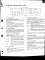
3. FRONT PANEL FACILITIES
dDffi
O poweRswtrcH
Power is suppliedto the stereo amplifieras soon as this
switch is depressedto the ON position.
The power is turned off when the switch is releasedto the
OFF position.
@ sass coNTRoL
This is usedto adjustthe bass(low-frequencyrangelsound.
Rotatethis control with the TONEswitch depressedto the
ON position. The bass is emphasizedwhen the control is
rotated clockwise from its center position and attenuated
when it is rotatedcounterclockwise.
@ rnealE coNTRoL
This is used to adjust the treble (high-frequencyrange)
sound. Rotatethis controlwith the TONEswitch depressed
when the conto the ON position.The trebleis emphasized
trol is rotated clockwisefrom its center position and attenuatedwhen it is rotatedcounterclockwise.
swlrcH
@ REcour sELEcroR
This is usedto selectthe output signalwhich is fed out to the
T A P ER E C1 , 2 i a c k s .
COPY 1 ) 2: The output signalis fed out from the TAPE 1
PLAY jacksto the TAPE2 RECjacks (when
dubbinga tapefrom TAPE1 to TAPE2).
The
output signalfrom the TUNERjacksis
TUNER:
fed out to the TAPE 1 RECand TAPE2 REC
jacks.
The output signalfrom the PHONOiacksis
PHONO:
fed out to the TAPE 1 BECand TAPE2 REC
jacks.
The output signalfrom the AUX jacks is fed
AUX:
out to thE TAPE 1 RECANdTAPE 2 REC
jacks,
@ pnonesJAcK
your headphonesto this jack when
GOnnectthe Plug on
inPrivate'
to aProgram
listening
)
o
@ rurucloNswtrcHEs
Theseare usedto selectthe sound source' At the left of each
switch there is a function indicator (pictographic)which
lights when the correspondingswitch has been depressed.
This indicatesthat the lightedfunction has beenselected.
PHONO: Depressfor playingrecordson a turntableconnectedto the PHONOjacks.
TUNER: Depressfor listeningto a program on a tuner
connectedto the TUNERjacks.
Depressfor listeningto the sound from a stereo
AUX:
componentconnectedto the AUX jacks'
TAPE 1: Depressfor listeningto a tape in a tape deck
connectedto the TAPE 1 jacks or to monitora
recording.
Depressfor listeningto a tape in a secondtape
TAPE 2:
deck (or other adaptorcomponent)connected
to the TAPE2 jacksor to monitora recording.
NOTE:
Depress only one function switch at a time. The desired program
source may not be selected if Nvo or more switches are depressed
at the same time.
O eeLeltcEcoNTRoL
This is used to adjust the balance of the sound from the left
and right channels. When rotated clockwise from its center
position, the volume ol the left (L) channel is reduced; when
rotated counterclockwise, the volume of the right (R) channel is reduced.
@ voluruEcoNTRoL
This is usedto adjustthe volumeof soundheardthroughthe
speakersor headphones'No soundis heardwhen it is set to
the "0" position.To increasethe volume,rotatethis control
slowlyclockwise(C)),
@ louoruEssswlrcH
this switch is
The bass and treble sound is emphasized when
(LOUDNES'S indicator lights)
position
ON
to
the
depressed
The sound
un'der low volume listening conditions'
is
low'
volume
alive even when the
1. SPECIFICATIONS
Amplifier Section
Continuous
Power
0ueutis 35watb*perchannel,
min.,atI ohms
from20HerEto20,000
Hertwithno
morethan0.009%
totalharmonic
distortion.
Total HarmonicDistortion(20 Hertzto 20,000Hertz,I ohms,
from AUX)
continuousratedpoweroutput ....... No morethan0.009%
17.5watts per channelpower
output .. . .. .. .
No morethan0.007olo
fntermodufationDistortion(50 Hertz:7,000Hertz=4:1,
8 ohms.from AUX)
continuousratedpoweroutput .. .. .. . No morethan0.@7o/o
17.5watts per channelpoweroutput No morethan0.00S7o
DampingFactor(20Hertzto20,000Hertz,8 ohmsl ..........S0
Input Sensitivity/lmpedance
PHONO
. .. .. 2.5mV/S0kitohms
T U N E RA, U X ,T A P EP L A Y1 , 2 . . . . . . . . . . 1 5 0 m V / 5 0 k i t o h m s
PhonoOverloadLevel(T.H.D. 0.004o/o,
1,000Hz)
PHONO
. 1zt0mV
Output {Level/lmpedance)
T A P ER E C1 , 2 . . . . . . . . . . . .
1ûnV/2.7 kitohms
Speaker
A/OFF,BIOFF(6ru169)
FrequencyResponse
PHONO(RIAA Equalization)
20 Hz to 20.000Hzr0.5 dB
TUNER,AUX, TAPEPLAY 1, 2 ..... 5 Hz to 100.000Hz:$dB
Tone Control
B A S S. . . . . . . . .
. . . t 8 d B f i 0 0H z )
TREBLE
. . . . . . . .=. 8 d B ( t O k H z )
LoudnessContour(Volumecontrol set at -40 dBl
+ 6 dB fi00 Hzl, + 3 dB fiO kHz)
Hum and Noise(lHF, short-circuitedA networkl
PHONO
. . . 7 0d B
T U N E RA, U X ,T A P Ep L A y 1 , 2 . . . . . . . . . . . . . . . . . . . . . .l.0. .o.d B
Muting
. . . . . .- 2 0 d 8
Miscellaneous
PowerReguirements
lfry,ffiHz
PowerConsumption
1g0Watts (UL)2æ VA (CSA)
Dimensions
. . . . . . . 4 2 0( W )x 9 8 ( H l x 3 6 7( D )m m
1 6 - 9 / t O( W l x 3 - 7 1 8( H l x l z t - I 1 / 1 6( D t i n
Weight (withoutpackage)
.. .. 6.8 kg fl4 lb S oz)
Furnished Parts
O p e r a t i nIgn s t r u c t i o n s
............1
*Measured pursuant to
the Federal Trade Commission's Trade
Regulation rule on Power Output Claims for Amptifier.
NOTE:
Specificationsand design subjectto possiblemodilication without
notice.
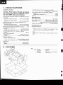
2. PACKING
No.
Part No.
t . AHA-292
2. ARB-416
3 . AHD.922
Description
Side pad
Operating i nstructions ( English)
Packing case
6
I
(
I
1
xvt{ ,tooz
(BHSl'|nSiln
xv;i tûgr lYfo-t
0lH3l tns
zH09
^o?trt
I
I
o
I
d-c8ggfitdtt
xo899tl,ll1N
088qsz
Êttosz
ro'r
69zzarsz
oN adII
âd,(I
oN ed^I
lvlôLszJsz
lvltoJJvsz
9Z9ZCSZ
o01lvsz
916]CSZ
9Ê/l.csz
906VSZ
o98VSZ
v9t6csz
vesrvsz
9t8t3SZ
00?lcsz
910]VSZ
?88I.CSZ
a
09tvsz
o
D
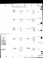
sCl pueslolslsuerl ;o ecuereaddylatratx3
0r
I,L
ZI,
-t
1
2
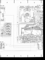
7. P.C. BOARDS CONNECTIONDIAGRAM
LOUDNESSAsJy
2
4
5
o70!
os3
os
4r2
or€
o422
e@
oæa
@
tE Ars'y
5
6
--T
10
11
|
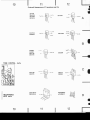
ExternalAppæranceof Transistorsand lCs
2SA750
2SA1015
2SC1400
2SC1815
Sulfix
Lot No
2SA733A
2SC945A
2SC19144
hFE
2SA850
2S4905
2SC1735
2SC19t5
TyPo
-Type
No
2sjc,225g
TOI{E COt{TRo|-Ass'y
FEAOPTIONES
JACK Ass'y
Lot No
hFE
Suflix
2SA1100
2s'C2575
2SD313
2SD880
2SA11@.|Al
2SC2579lAl
NJM4558t)X
pP0I558C-P
Lot
o
o
e
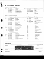
6. EXPLODEDVIEWS
PartsList of ExteriorComponents
No.
Mark
1.
2.
3.
4.
Part No.
Descraptaon
ANE-345
VBZ30P060FMC
ANM-027
AAB-271
Top cover
Screw 3xG
Front panel assembly
Knob (BASS,TREBLE,
REC OUT SELECTOR}
Knob (VOLUMEI
5. AA8-270
Mark
No.
6.
7.
8.
9.
Part No.
Description
Knob(BALANCEI
AAB-272
Nut
NKXlFUC
W A X 1 F 1 6 0 U 0 5 0 Washer
BBT3OPOSOFZK Screw3x8
Lug
Bottom plate
1 0 1.
102.
PartsList of Interior Components
No.
Mark
A
Part No.
1 . ATT-800
2. VXZ40P080FMC
3 . AEC-383
4.
5.
6.
7.
8.
9.
10.
a**
*t
**
AAD-338
VBZ30P060FMC
ABN-O24
ABN-028
A8A-261
GWX-661
ASX-203
11.
12.
13.
14.
ASG-521
........
AEC-818
2SC2579lAl-O*
QSC2579{At-Y*l
15. 2SA1104lAl-O*
(2541104/A/-Y*l
Description
Powertransformer
Screw4x8
Foot assembly
Knob (POWER)
Screw3x6
Washer faced nut
Nut
Screw 3xG
Indicator assembly
Remote slide switch
(BEC OUT SELECTOR)
Push switch (POWER)
I n s u l a t o rs p a c e r
Transistor
Transistor
*hfe should have the sarne value.
A**
,4\
16.
17.
18.
19.
20.
ABA-258
AEK-101
GWK-180
ACG-019
AEC-510
2 1. ABA.252
22. AKP.O41
23. BBT3OPOSOFZK
Screw3x16
Fuse (3A/125V)
AF assembly
Ceramic capacitor (0.O1/ACl 50V)
Nylon rivet
Screw 3x8
AC socket (AC OUTLETS)
Screw 3x8
No.
Part No.
Description
24. MTZ3OP1OOFZK
25. AÉ.C-327
Screw3xl0
Strainrelief
26. ADG-052
27. AKE-051
28. WA35F100N080
AWX-212
AC power cord
Terminal (SPEAKERS)
Washer
Composition assemblV
(Function switch ass'y+ Tone
control ass'y)
101.
102.
103.
104.
105.
Frame
F l e x i b l ej o i n t
Panel stay
Mounting plate
106.
107.
108.
109.
11 0 .
Tone control assembly
S h i e l d i n gc a s e
Wire clip
Headphonesjack assemblY
Function switch assembly
111.
112.
11 3 .
114.
115.
Volume assembly
Loudness assembly
P.C. Board spacer
Right frame
Heat sink
11 6 .
1 1 7.
Rear panel
Terminal (GNDI
Holder
RearPanelView
Terminal ffAPE 1)
AKB.O78
a
o
Terminal{TAPE2)
AK8-078
Terminal(INPUT)
AKB€79
2\ AC socket(AC OUTLETS)
AKP.O41
(
I
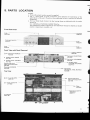
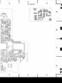
5. PARTS LOCATION
NOTES:
o Parts without part number cannot be supplied.
o The [. marh found on some component parts ind.icates the importance of
the
safety factor of the part. Therefore, when replacing, be sure to use parts of identical
designation.
o For your Parts stoch control, the fast mouing items are indicated, with the marks
** and *.
**
GENERALLY MOVES FASTER THAN *.
This classification shall be adjusted. by each distributor because it depends on model
numb er, te mperature, h u mid ity, etc.
FrontPanelView
Knob
Top cover
ANE.345
AAD.338
Knob
AAB.270
t (
Knob
Knob
AAB.272
AAB-271
Front View with PanelRemoved
A**
lndicator assembly
GWX661
Pushswitch(POWER)
ASG-521
Pushswitch (FUNCTION)
ASG408
Variable resistor (BASSI
ACT-140
*
Pushswitch {LoUDNESSI
ASG-278
Variableresistor(TREBLEI
ACT-140
Remote slide switch
*
( R E CO U T S E L E C T O R }
ASX-203
Phonelack (PHONES)
AKN.O3O
Top View
A **
[
*
ruse(3Al125vl
AEK-101
Variableresistor
(VOLUME,BALANCE)
ACV410
**
Pushswitch
(SPEAKE
RS,TONE,MUTING}
ASG-288
**
Remoteslideswitch
( R E CO U T S E L E C T O R }
ASX-169
Power transformer
ATT€OO
**
Relay
ASR-033
Electrolytic capacitor
(5600/s0v)
ACH-211
AF assemblY
GWK.180
I
o
o
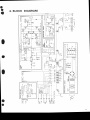
4. BLOCK DIAGRAM
Ç
--*
o
I ^e
g---i
-
ù
E
(,
co
z
o
F
(J
UJ
F
o
É
o-
6
È
J
G
o
trg
="â
F()
@
z-Ë
oo
À | -UI
<l
G
E
D
E
z
to
ô2
F ô-----?-À
6-Ë
q
o
0
o
o
I
j*Ë
Àu È
LIJ
:
&
L
,F-l
-l>
I
<lE I
I
lli
È
{-;t
tEl
tol
tôl
l-l
o
e
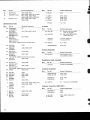
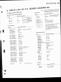
9. ELECTRICALPARTS LIST
NO?ES:
o When ordering resistors, first convert resistdnce ualues into code form as shown in
the following ex.amples.
Ex. 1 When there are 2 effective digits (any digit apart from O), such as 56O ohm
and 47h ohm (tolerance is shown by J = ïVo, and K = 10Vo).
561 ..
. . R D % P Si s @ | n J
56x 10t
560a
RD%PS @ABJ
473 . .
47 x 103
47ha
0.5a
lsr
-
I
0R5..
or0 . .
....
R N z HC I E E K
asrP@$@Iç
Ex. 2 When there are 3 effective digits (such as in high precision metal film resistors).
5621. .
562 x Io0
. . RNZSR EGlE[nF
5.62ha
o The S marh found on some component parts indicates the importance of the
safety factor of the part. Therefore, when replacing, be surc to we parts of identical
designation.
o For your Parts Stoch Control, the fast moving items are indicated with the marks
** and *.
THAN *.
**
GENERALLYMOVESFASTEF
This classification shall be adjusted by each distributor because it depends on model
number , temperature, humidity, etc.
MiscellaneousParts
Mark
Part No.
* ATT-Boo
A
4 ** AEK-rol
a ** AsG-521
Acc{re
A
**
**
**
**
CKDYF 223250
2SC2579lAl-O.
(2SC2579lAl-Y*l
2SA1104lAl-O*
(2SA1104lAl-Y*l
Symbol & Description
Mark
T1
Powertransformer
FUI Fuse(3A/125V)
Pushswitch (POWER)
S1
Ceramiccapacitor(0.01/ACl50V)
C1
c901
01. 02
03, 04
*hfe of 01 -Cl4 should have the same value.
AKEOsl
AKP{41
ADG.O52
GWK-180
GWX661
Terminal (SPEAKERS)
AC socket (AC OUTLETSI
AC power cord
AF assembly
Indicator assembly
AWX-212
Compositionassembly
(Function switch ass'y+ Tone
control ass'Vl
Part No.
Symbol & Description
C E A4 7 1M 6 L
CEA R47M sOL
CEANLOlOM
50
C E A N L2 R 2 M5 0
C E A N L4 R 7 M 5 0
c501
c503
cl3, Cl4
c!.19,c/.20
c3. c4, c409,c410
ccDsL 150J 50
ccDsL151K500
ccDsL 100D 50
ccDsl- 560J 50
ccDsL 820J 50
er05. gf06
u27-U30
c/31.cr'.32
c421,U22
c/,o3,@o4
ccDSL 561J 50
coMA 392K 50
coMA 562K 50
c/o1,uo2
c11,C12
c7, c8
coMA 152K 50
coMA 183J 50
ACH-356
c9, cl0
u11-Ul4
(0.47l50V1
C504,C5O5Electrolytic
RESISTORS
(GWK-I80)
AF Assembly
CAPACITORS
-
When ordering resistors, conuert the resistanceualue
into code form, and then rewrite the part no. as before.
Mark
Part No.
Symbol & Description
ccDSL 221J 50
ACH-211
ACG-o19
ACG-o17
C E A1 0 1 Ml O L
c 1, c 2 , u 2 3 - U 2 6
(5600/50V1
C703,C704 Electrolytic
C E A1 0 1 M2 5 L
CEA 221M sOL
lOL
CEA4TOM
CEA 47OM25L
c502,c710
c707
c705
c407,c4oB,c701, c702,c711,
c712
u17, C418
c301.c302
Part No.
r c92-063
o
o
-
C E A3 3 1M s O L
cEA 100M50
RDz4PMtrtrtr J
C 7 0 8 C e r a m i c ( 0 . 0 1/ A C l 5 0 V )
C 7 0 9 C e r a m i c ( 0 . 0 1/ A C l 2 5 V )
c5, c6, ot1 s, erl6, c706
ACN-045
ACN-070
Symbol & Description
VR1, VR2 Semifixed(100-B)
R1-R27, R401-R406, R413-R41 6,
R419, R420, R429-R440,
R445-R452, R501-R503, R505,
R509-R512,R703,R704,R706
R705
Wirewound l270l5Wl
R443, R444 Wirewound
1o.22+o.22l2Wl
Mark
A
A
Part No.
Symbol & Description
RS1PtrtrtrJ
RDT4PMF
trDtrJ
R465, R466. R50l
R201,R407-R412,R417,R418,
R421, R422, R425-R428,
R453-R460, R701, R702, R707
R441, R442, R461-R464,
R506-R508
RD%PSF
trtrtrJ
A
It/hrk
*
Part No.
**
**
**
**
**
**
**
**
**
Symbol & Description
2SA733A
{2SA1100}
2SC945A
(2SC2575)
o701
2SC1735-C*
(2SC1
735-D*l
2S4850-C*
(2SA850-D*l
0,419,4420
Mark
Part No.
Symbol & Description
**
ASX-169
51
**
ASG-288
52
0403, 0404
2SA1015-Y*
(2SA1015-GR'l
2SC1815-Y*
(2SC1815-GR'l
0405, 0406
TONE, MUTING)
**
Mark
**
Mark
o505
0501, 0502
Q401,0402
0703
ASR€33
RLl
VB23OPOSOFMC
Screw 3x8
Relay
Part No.
Symbol & Description
ACV-410
VR3 Variable resistor
(VOLUME/BALANCE)
AKN.O3O
152473
(1515551
(1520761
MZ-230
lw2-2301
D401, D402, D405-D408, D419,
0420, D501-D505
MZ-157
D506, D702, D703
4423,0,424
D701
**
Phones jack (PHONES)
llart No.
Symbol & Dercriptaon
coMA 563K50
ccDsL 221J50
Cl01,Cl02
Cl03,Cl04
RD%PM123J
RD%PM101J
R 1 0 1 ,R l 0 2
R105
ASG-278
53
Pushswitch(LOUDNESS)
IndicatorAssembly(GWX-661
)
Mark
Dzl1s:Dullg
D403, D404
Symbol & Description
LoudnessAssembly
Mark
MZ-100
(w2.1001
Terminal (TAPE1, 2)
Terminal (lNPUTI
Part No.
0407, 0408
2SC1384
2SC19144
2SC2259
2SD313
(2SD8801
2SC1915
*
AKBO78
AKBO79
Headphones
JackAssembly
**
**
**
**
(wz-1571
* 0523R0
Remote slideswitch (REC
OUT SELECTORI
Push switch (SPEAKERS.
should have the same value.
2541015
{2SA733A}
0409, 0410
*
THl, TH2
OTHERS
4421,0,422
*hfe of C1405-O408 should have the same value.
*
D411-D414
D409,D410
D708. D709
D7U-D707
VolumeAssembly
254905
*
D710
0503, 0504, 0702
**
**
MZ-O47
TH103-2
NJM4558DX
o1
(pP@558C-Pl
2SC1400-E*
a 4 1 1 , 0 4 1 2 ,O 4 1 7 ,O 4 1 8
(2SC1400-U*l
(2SC2603/A/-E*l
(2SC2603/A/-F*)
o413-0416
2SA750-E*
(2SA750-u*)
(2SA111s/A/-E*)
(2SA1 1s/A/-F*l
'hfe of O411-O418 shouldhavethe samevalue.
*hfe of 0419-Q422
**
Ùmbol & Dercription
* 152473
* STV2H
* 10E2
* GP.2OD
SEMICONDUCTORS
Mark
Part No.
Part No.
Symbol & Description
RD%PM431J
RD%PM1O1J
R201
R202
* AEL.346
* AEL-324
D201-D207, 0209-0211
D208
I
a
4
5
6
NO?E:
The indicated semiconductors are representatiue ones
only. Other alternatiue semiconductors may be used and
are listed in the parts list.
AF As'y
at5
c/lo
cWK- i8O
R4€
l@i
ot t2
03,4
2sc2579r^ |
2SA|1O4rA /
/s
O4O,4O2,4O3- 4O8,
04il-4t4 ,4t9,420
ts2473
,Rq
\24
QSO| , 5O2
25Ci914A
PROTECTION
Qæt
O 7!H
-
i;.^;";l
Fvlli,'ïvi"l i
:ÏJ
Ras
r39r
HEAOFHONES
JACK
A$'y
rd€
t
oæ3, 4o4
Mz-roo
?!"ro *i:" in
8198*o'o
i-ffi
-]*-^
lG;te-'l
" ]*-'
--N
PRoTEcrloN I oFF
4Ot t4o2
403-406
æ7,4OA
4O9, 4fO
411 .412
25C2239
2SAlOlS
2SCrAr5
2SA9O5
2SCi4OO
0413-416
Q4t7 | 4A
O49, 4ilo
O42t , 422
O423,424
254750
2SCr400
2SCr735
26A850
2SCr915
rr Â1T-@
A
AMP J
Â!tr
-
SNICED
ûSÎCHED
M52
22r
aæ - 052
aii"î,3'
as6-321
I
c422
sp
4
vRr,2:
"tâfÂ
rru CuffiftÎ ÂOJ
c92-@
I
5
6
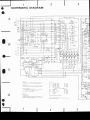
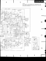
8. SCHEMATICDIAGRAM
FUNCTION S W I T C HA s s ' y
--1
LCH
r
TAPE2
PLAY
"--l
I
s?
|
E"_
*"""
I
Ç"3.1
lr5ohvl
r
TAPE I
lt!g!!,-
PLAY
REc
AUX
liæ;nl
TUNEFI
IEhl
PHONO
tzhg
sr r FUilcTld
asc-€a
TUNER
s2: RECW
SELECTOR
AUX
TUNEF
TAPE I
L
/
--1-
PHOIO
PLAY
r REC
IAPE.2
l_
LOIJDNESS Ass'y
,
I
83t
lhS
i
voLWE / BAUW
(LODNESS)
I
59J lh4
3l
I l,æoa
s3-!-.1 $r-z
caQ2
oos
lOUDNE$
a5G-2?6
gll o
]
se-r I
I
RESISTORS:
fndicat€d in tt, %W, !5% rote.arc€ unt*
M : Mo, (F) | 1l%, {G) : !2%, (K) : r tO
swtlcHEs:
orheruis
notd
k : k0
st-r
SI-2
St.3
SI-4
SI.5
52
,(M):tzo.Élot€rJnce
2 CAPACI.rOFSi
Indicâted in capâcity (! Fl/votra$
{Vi unlæ othrNis
noted p : pF
Indication wirhout vottaæ is SoV except etætrolytic
côpacitor
3 VOLTAGE, CURRENTI
I
t
geoutpur(1kHzl
35
w+
35
fJrsighalvoltasil
w
| Dc vohag€ {Vl ât no input 3isnâl
T]
Vatue In {
I is DC vohæ at ratd power
mA i DC current at no inf t signâl
ê
s34
S4
s5
4 OTHERS:
Signal rilre
+:
@ : Ad j!îiîg
widr
Th€
mâû fad
on eme cohFmr
idi€t6
Fdr
Â
ot the stety fæbr of rh€ psft. Therefore,
Nnæe
whm
F arc to u$ Fft
of ideilicat dBigndbn.
1
Tb
: FUNCI|ON (PHONOI
- OFF
QA
(TUNERI
: FUNCTION
ON - OFF
: F U N C T I O NI A U X )
ON - OFF
; F U N C Î I O N( T A P E I )
ON - OFF
: FUNCTION(TAPE2)
ON _ OFF
: REC OUT SELECTOR
_
COW I>2
TUNER PHONO- AUX
SPEAKER(A)
CN _ SF
SPEAKER(B)
6[çr
TONE
ON- ôiE
MUTTNG r-zodgr
or _ 6F
LOUDNESS
ON _ OFF
POWER
OF
ON-
ùderlid
;ftlicat6
trc *ircà
æsirion
the im,
rÇtæing,
This is ûe hÊic .doarb
diâgffi.
due b improvemenrs in d6iqn.
2
but the æùat
cr@û
may vâry
3
l
o
o
e
FunctionSwitch Assembly
Mark
**
Part No.
Symbol & Description
ASG-408
RD74PMl
OlJ
51
Pushswitch(FUNCTION)
R13
Tone Control Assembly
CAPACITORS
Mark
Part No.
Symbol & Description
coMA 333K50
coMA 122K 50
coMA 124K50
coMA 822K50
ccDsL 390J50
c1,c2
c5, c6
c3, c4
c7,c8
c11. C12
RESISTORS
I
Note:
Mark
When ordering resisfors, conuert the resistance ualue
into code form, and then rewrite the part no. as before.
Part No.
* ACT-140
* ACT-140
R D % P Mt r I ] O J
o
o
Symbol & Description
VRI
VR2
Variable(100k-8.BASS)
( 1 0 0 k - BT, R E B L E )
Variable
Rl_R12
I
e
10. AJUSTE
Ajuste de la corriente la corriente devatiada
o Girar la VRl (L, izquierda) VR2 (R, derecha)
totalmente en la direcciôn hacia la izquierda.
o Sin ninguna carga o sefral de entrada, girar el
internrptor de la alimentaciôn (POWER) a ON y
manténgalo por 10 minutos.
Punto de ljurte
Valor dotorminado
Terminal de medida
lvRl (L)
31 mVt13mV
TPI (+) v TP2 (-)
VR2 (RI
31 mVt13mV
TP4 (+l y Tp3 (-l
I
I
Extraer la tapa
a
a
20
O
o
e
10.RÉcuce
Réglaç du courant déwatté
o Tourner à fond VRl (L, gauche) et VR2 (R,
droite) en sensinverse des aiguilles d'une montre.
o Sans charge ni signal d'entrée, allumer I'intermpteur POWER et le maintenir 10 minutes.
Point de
r6slage
Valeur prccrite
Tcrminal de
mo![trt
VRl (LI
3 1m V t 1 3 m V
TPl (+l et TP2 (-)
VR2 (R}
3 1m V t 1 3 m V
TP4 (+) et TP3 (-)
Enleverle couvercle
vR2- @
@-vnr
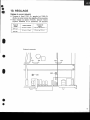
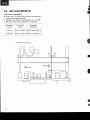
1O. ADJUSTMENTS
ldle Current Adjustment
o T\rm VRl (L) and VR2 (R) fully around in the
counter-clockwise direction.
o Without any load or input signal, tum to POWER switch ON and let stand for 10 minutes.
Adjustment
point
Prescribed
value
Measuring
terminal
vR1 (L)
31mV t13mV
TPl(+) and TP2(-)
vRz (R)
31mV j13mV
TP4(+) and TP3(-)
I
. Removethe top cover
TP4
II
vR2-@
@vnr
a
e
(D rrloNeefl'
a
I
ORDERNO.
ART- 621-0
NON
S\A/ITCHING
AMP
S T E R E OA M P L I F I E R
HE,HB
The basic performance of the HE and HB types is the same as the KU Çpe, pleasereferto the KU type
servicemanual (ART€20) with the exception of this supplements.
SPECIFICATIONS
The specificationsfor HE and HB types are the same as the KU type except for
followingsections:
Amplifier Section
Hum and Noise(DlN, continuousPower/S0mW)
.72d8/64d8
PHONO.
....95d8/69d8
TUNER,AUX,TAPEPLAY.
Miscellaneous
Power Requirements
PowerConsumption
. . .22OV/240V (Switchable)
50/60H2
.....250W
Line VoltageSelection
Line voltagecan be changedwith followingsteps.
the AC Powercord.
Disconnect
Removethe top cover.
Take out the fuse (AEK-018)from the fuseassembly.
Be-install the fuse.in the correct voltage indication
( s e eF i g . 1 ) .
5. Stick the line voltagelabelon the rearpanel.
1.
2.
3.
4.
Part No.
(T1.25A|AC250Vl
rEK-018
_,>[l=F'!
Fuse(T2.5A/AC250Vl
(HEtypeonly)
Description
AAX.193
22OY label
AAX-192
240V label
Front panel
F i g .I
O
Ç
Tokyo 1ss. Japên
Mesu.o-ku,
4-1 . Mesuno 'l-chome,
CG,FIPG'RAI|G'N
ELECTFIG,NIC
PIC'NEEFI
New Jereev 07074.l-JgA.
Ets oxfond E)eive, Moonêchie.
crctElPoFlaTlcl\l
Et-EcTFtct\||cia
u.B. Ffct\fEFf
9, 2O3O AnÈwenp. Belgium
aE|JF|CrFEt N,V. Luithegen-Heven
FIGTNEEFI ÉECTFICINIC
Road, Bneeside. VicÈonie 3195, Aust.tl'Ê
Boundeny
PTY. LfEt. 178-184
Â,uIATHALIA
FfGI\fEEFl ÉEGffE|GrNtCG'
Y L
@A P R . 1 9 8 1
Prinred in laPan
I
CONTRAST OF MISCELLANEOUSPARTS
NOTES:
o Parts without part number cannot be supplied.
o The A mark found on some component parts indicdtes the importance of the
sdfety factor of the part. Therefore, when replacing, be sure to use parts of identical
designation.
o For your Parts Stoch Control, the fast mouing items are indicdted with the marks
** and *.
**
GENERALLY MOVES FASTER THAN *.
This classification shall be adjusted by each distributor because it depends on model
number, temperature, humidity, etc.
I
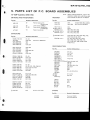
P.C.BOARD ASSEMBLY
Part No.
Mark
Symbol & Description
AF assembly
KU type
GWK-180
HE type
GWK.182
HB type
Remarks
GWK.182
E L E C T R I C A LP A R T S
Part No.
Mark
Symbol & Descriptaon
A*
A*
T1
T1
A**
A**
A**
FUl
FU1
FU2
Powertransformer(120Vl
Powertransformer
1220V,240V1
Fuse(3Al
Fuse(T1.25AIAC250V)
Fuse(T2.5A/AC25OV)
A**
51
Cl
P u s hs w i t c h ( P O W E R )
Ceramic capacitor
/\
A
(0.o1/Acl50vl
ACsocket(ACOUTLETS)
AC power cord
KU type
HE type
HB type
:t:::
ATT-802
ATT.8O2
t.i.'l'.
AEK.O18
AEK-403
AEKOl8
ASG-521
ACGOl9
ASG-522
:::::1
AKP-041
ADG.O52
AKP€26
ADG{41
AKPO44
ADG-051
Remarks
F U R N I S H E DP A R T S
Part No.
Mark
Symbol & Desciiption
(English)
Operating
instructions
Operatinginstructions
(English,
French,German,ltalian)
KU type
HE type
HB type
Remarks
AR8-423
a
t
2
PartsList of AF Assembly(GWK-182)
**
CAPACITORS
A
Part No.
Symbol & Description
ccDsL 221J 50
ACH-211
c1,c2,u23-U26
ACGO{9
C E A1 0 1M 1 O L
C E A1 O 1 M2 5 L
C E A3 3 1 Ms O L
C E A4 7 1M 6 L
c707
c705
c407,c408,c701.C702,C711.
c712
u17, C418
c501
CEA R47M 5OL
C E A N LO l O M5 0 L
CEANL2R2M 50L
C E A N L4 R 7 M5 0 L
ccDsl 150J50
c503-c505
cl3, Cl4
c419,C420
c3, u. c409,c410
c405.c406
ccDsL
ccosL
ccDSL
ccDsL
ccDsL
c427-U30
c/.31, C432
u21,C422
c403, gr04
c/io1,uo2
CEA 221M 5OL
C E A4 7 O Ml O L
CEA 47OM25L
,fr
ls1 K 500
100D50
560J 50
820J 50
561J50
coMA 392K 50
coMA 562K 50
coMA 152K 50
coMA 183J 50
cEA 100M50
J
C7O3,
C7O4Electrolytic
(5600/50v)
(0.01/AC150Vl
C708
Ceramic
c5, c6. c415,@16,C706
c502,c710
Mark
**
**
**
c92063
VR1, VR2
RD74PMtrtrtrJ
R1-R27, R401-R406, R413-R41 6
R419, R420, R429-R440, R445R452, R501-R503, R505, R509R512,R703,R704,R706
R705
Wirewound l270l5Wl
R443, R444 Wirewound
lo'22 + g'2212v11
R412,R453,R454
R465, R466. R504
0413-o416
o701
0503, 0504, 0702
4419, A420
4421, A422
should have the same value.
**
2541015
{254733A}
0403, 0404
**
2SA1015-Y*
(2SA1015-cR*l
2SC1815-Y*
(2SC1815-GR*l
0405, 0406
**
**
**
**
**
**
**
*
When ordering resistors, convert the resistance value
into code form, and then rewrite the part no. as before.
Symbol & Description
2SA733A
(2SA11001
2SC945A
(25C2575)
2SC1735-C*
(25C1735-D*l
2S4850-C*
(2SA850-D*)
*hfe of 0419-0422
c l 1 ,C l 2
c7,æ
c9, c10
u11-U14
c301,c302
PErt No.
Symbol & Description
o,411,0412, O417,O418
'hf e of O41 1 -O418
should have the same value.
**
RESISTORS
Note:
**
Part No.
2SC1400-E*
{2SC1400-Ur}
(2SC2603/A/-E.l
(2SC2603/A/-F*l
2SA750-E*
(2SA750-U*l
(2SA111s/A/-E*l
(2SA111s/A/-Frl
0407, 0408
*hfe of Q4O5-O408
should have the sôme value.
2SA905
2SC1384
2SC1914A
25C2259
2SD313
(25D8801
2SC1915
o505
0501, 0502
0401, 0402
o703
152473
(151555)
(1520761
D401, D402, D405_D408,D419,
D420, D501-D505
0.423, A424
MZ-230
ACN€45
ACNO70
,A
RD%PMFtrtrtrJ
RS1PtrtrtrJ
A
RD74PMFLtrtrCJ
RD%PSFtrtrCJ
Semifixed(100-8)
o
Ç
**
*
*
*
*
*
*
R201,R407-R411, R417,R418,
R421, R422, R425-R428, R455R460, R701, R702, R707
R441, R442, R461-R464, R506R508
MZ-157
(wz-1571
o523R0
MZ-100
(wz-100)
D506, D702, D703
D415-D41 I
D403, D404
MZ-O47
D710
152473
STV2H
1082
GP-200
D411-D414
D409, D4lO
D708, D709
D704-D707
TH103-2
THl, TH2
PartsList of FuseAssembly
SEMICONDUCTORS
Mark
twz-2301
Mark
PartNo.
Symbol & Description
NJM4558DX
ûrPC4558C-Pl
o1
A
Part No.
Symbol & Description
ACG-001
c1
Ceramic capacitor
(0.01/Ac2s0vl
2
3
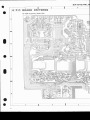
P.C. BOARD ASSEMBLIES
ô
A F A s s e m b l(yG W K - 1 8 2 )
o
-TÀPEI
REC
/ ô 1 O ^(!,@
o@
o@
EEC
tL,
PHONO
fr AY
A
r
",
ï
r ll";'i
t / ! I
1
(9/
TUNER
11
1i , i
I
tt
,l
i",
PLA!
ooo
ÂUX
i ; i o 4 s + "+: : : . r ' l o .
{Y
J o48l I
) i;r,
-
t.:.
I
JI
F7.5
À
, / R E CO U T S E L E C T O F
?
;
j-+
oo
65
.-ryrI
070
2SA733A
i'r
I'
ax
eÀ
T+
b
.Èr" l
:1,"1:
I
'
NJMA5SAOX
I D7A2
I MZ-
q
:;i
:
B
i9
o
J
fo .:.
r
I
I
I
Pow.' Tr
E
B
C
B
ô
2scl9l4a
O5O2
Qæ3r5@?SC945A
oæ5
2SCl384
0502.5O4
C
o€a
2sc1al5
0420
25C17f,5
04,4 2S4750
04ta 2sc14oo
D4r6.4ia
o5?!RO
5O5
152473
04rO 5TV2!
.
)}1_
D 4 4 2. ô \ 2 , 4 4 , 4 2 A
's2413
:il
D
o
t
*'l
t l i1 i
ïl
j:H
ï'
o702
2S945À
, ? (h
\ lÂ" ï
v
1
j
t
J
'
I
J
J"
T
ï
I
ï
"Zi.îi"
È{r
:?; -;ù
*', *l tl
*ro4v"1
*;"r :ii
II
lI ' "t1t"t.
,,,:,I o
ll
i'-,
I
'"T I T-*
i nr*
I
10
I
I
1æ
;1,,,.'
ir;,,J'1.::
I r illî 1
: : , 1- I r " , " { ;
I
t'.,"i
o I
o
50
"",T T'""
ï , ,
1
1
1i
o
51
L
o40
4
5
6
[
a
a
FuseAssembly
A
B
-o
rirltiiiiliËi{i}l
lËl
jJ:
D4r5,4l#
o523Rq+i
o42t
O42l
o4r3
o4r5
Q407
o4o9
o405
o403
2sc22s
o40
@o3,æ5 2SAror5
o@7
2ær8r5
Q@
2SAæ5
04ù
esctars
04t3,4r5 25A75O
Ml?
2SC|€O
@r9
25Ct735
D
o
)
3
2
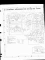
SCHEMATIC DIAGRAM
)
I
lt!q!l
ÎAPE I
tlgllJr
REc
Iiffil
TUNEF
lisdl
ÈoNo
l';;Tl
rUNF
.
TAPE I
REC
I
IAÆ 2
REC
I
----
i
I
t_
-
-l
-
le3
-1
LoUoNEsS Âst'Y
I
I
940
lilFr'l:r-*Fl , r
I
3tl*
L-
o4ot,æ2
os3-4o6
o€7, æ8
o€, 4io
O{it ,4t2
t_=
2SC
291(
2SC
2sA9
æCt
L p .
VOLUMÊ Âss'y
a!:tr
{F
I FEsrsTORs:
lndicôrd in !) ZW ,5% rolerânce unres orhe'wi* nord k
M Mr! {F) -l%, {G) '2% {K)
tO?.,(Ml !zo%rot.,J..
swrTcBEs
k0
2 CAPACITORS:
Indicatd in.àoaciy (!Fllvolree lvl ùnle6orheri*ootdp
pF
Indrcaron wrthout volrage rs 50V exceor elær.otync caoac'ror
J VOLIAGE CUFEENT
Sianârvoll+ar 35 w+
33 w
Sirourpur(tkH!)
---L]
OC volràse (vl ar no inpur sisnal
Vârve in (
) 6 OC votrâæ ar rârd power
O C t u . r e n t i l n o I n p u rs i g n â l
ëmA
sr-t
SI -2
sr-3
SI -4
SI.5
52
s5- 4
s4
4 OTÉERS
o
t
@ Adru$ing F,rr
rhe
m..k t@d oô sme cohponenr Fns ,dicar6 rhe im
Â
@n6ft. ot the slery rætor ol ùe p.n Th€relo.€ whên .@ræing.
be tu.e io u* pa(sol @n(icat Gi$ârion
FUNcTt6 {PHONOI
FUNCTION (TUNERI
FUNCTION (AUX)
FUNCTION (TAPE I'
FUNCTIil (TAPÊ?)
- OFF
QÙ
q-gEE
M-OFF
ON _ OFF
d-OFF
REC OUl SEIECTOF
C O P Y I > z - T U N E F - P H O N O- A U X
S P E A K E R( A I
9S_ GF
SPE&ER (8I
s- sF
TONE
MUTING
(_20dB)
LOUONESS
POWER
ïhe underlind idicar6
rhe vtch
ON_
ON -
OFF
OFF
S_
O_
OFF
OFF
pslion
This k rhe ba.ic shù.tic
di4.âm, but rhê ætuât cird[
due to rmProvemenr3in d6iF
2
may vâry
4
5
a
NOTE:
The indicated semiconductors are representativeones
only. Other alternatiuesemiconductorcmay be usedand
are listed in the parts list.
AF As'y
I
GWK-182
ot,2
03,4
2sc2a79ra I
8ilO4 tA '
D0, €2. æ5- 4Oa,
D4t!!414 | 4r9,420
rs2{75
oSot,3o2
2SCt914A
A
Bf
oæ3, æ4
M2-rOO
re,4ro
*vd
ROL A6s'y
0413-416
o4r?, ar8
o49, 420
o42r, æ2
Q423, 424
I
I
2SA75O
2scl4æ
2SC1æ5
2SA85O
2æt9t5
I
s*rrcHEO
rclA@td
UÉUrc@
r@ ra
i-e
'#J'ffo*' ""Ëflffi t"tr*"
4
5
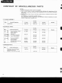
2, CONTRAST OF MISCELLANEOUS
PARTS
some compon"ns partljndicates
'I'herefore,
the importance of the
when replacing, be sure
to useparts ol, identical
P.C.BOABD ASSEMBLIES
AF amplifier assembly
Tone control assembly
S w i t c h a s s e m b t y( A l
GWK-143
GWG-137
Gws-212
Switch assembly(B)
VoJume assembly
Headphone assembly
GwK-154
GWG.144
Gws-238
GWK-1 54
GWG.144
GWS-238
GWS.213
Gws-239
GWS-239
GWX457
GWX-492
GWX.492
GWX458
GWX-493
GWX.493
GWX-494
GWX-494
F u s ea s s e m b l y
OTHERS
Symbol
Part No.
Description
KU type
HB type
HE type
Front panel assembly
ANB.848
ANB.896
AN8-896
Arr
Power transformer
ATT.666
AÏT-705
ATT.7O5
A ru r
Fuse (3A)
A E K - l0 1
Arur
F u s e{ 1 A )
AEK4O2
AEK-402
I ru za,
I ru+
F u s e( 2 . 5 A )
AEK.4O3
AEK-403
A56
L e v e rs w i t c h ( P O W E R )
ac1
C e r a m i cc a p a c i t o r
A
Fuse (2.54)
AEK.4O3
ASK.52O
0.01/250v
ASK.521
ASK-521
ACG-001
AC socket
AKP-032
AKP-O44
AKP-026
AC power cord
ADG{23
ADG.O51
ADG.O41
Screw
ABA.145
A B A - 11 6
A B A . I1 6
P A C K I N GA N D F U R N I S H E D
PARTS
Symbol
Description
O p e r a t i n g i n s t r u c t i o n s( E N G L I S H )
Part No.
KU type
HB type
ARB-352
AR8-366
Operatinginstructions
(GERMAN/FRENCH}
P a c k i n gc a s e
HE type
ARD.148
AHD.749
AHD-776
AHD-776
EiA-51g,l|{Ê,
I
HEI
t ^]r?)rDl
IEC
ott:'y'ri;:';r*'iÏ:rt#;F
BoARD
P'c'
oF
Lrsr
5.PARrs
"i
^
L
-..r^rrr (GWK'1541
tcwK-154)
'-AMP 'Asembly
AF ''trrr'
AF
'-raoÀiÉEl
TRANSFoRMER
AND
sWlTcHEs
sv.uol l!D"!9'i491
Part No'
ASK-172
A S K - 17 1
Pj't!9'---
Remote
"'o'-iËJil'o*,
s1
ASx-115
st
(TAPE2)
Leverswitch
12
Heater transformer
i'.,r.
A-fl'577
tnu 'v"
ii"ï'"t'it"
'*"
':":'*":'"'*"otton
symbol & DescriPtion
"'"-'
--â.ôrrrEr
REslsToR
"-'
(BALANCE)
Variable SOOk
AcN-o7o
iï"' '*,..ntl|j3iil,?i
CAPACITORS
É
Patt No,
R D % l|',wMt u u "u
-
nar _R50. RS3,R54, nov,^.1,
;;;-:À;;:'ll
42v
1-nss' R105'R106'
rz
Ëiôe-âr
SEMICONDUCTOBS
cEA 1O1M 1OL
:3i
::â13iil
'totr.'o
àii
"'n
.EANL
---,
2R2M bo
cEANLlooM 16
CEANLR33M50
oroni-uoi"ro
C C D S L O 3 O C5 0
CCDSL IOOK bOO
-
Part No'
C83, C84
'u'
3?1,
"uo'
c25,c26
c7'CB
C5' C6' C21 'C22'C2}-C32
c c o s L 8 2 o J5 0
c 3 5 ,c 3 - 6
50
5601
ccDSL
c15'c16'c27'c28
c c D S L 1 8 1 K5 O O
c43-C46
c E A 2 2 1 Mi o L
cKDyF 223zso
CKDYX 473M25
CKDYA 1O2J50
c17,c18
c a g :c 4 o , c 8 9 , c 9 o
c78-C81
c85-C88
CKDYA 122J5O
éô*À teil so
coMA 563J 50
coMA 683J50
C E A N LR 4 7 M5 0
[ncc-oo+
2sA798
0 1 7 '0 1 8
07' oB
015' 016
2SC1919
2SCtBt5
2SC1775A
2Sg3A4
03, 04
OS, 06
O9'o10'O13'O14
A23'424
?3??33t
332
1s2o76
D 1 - D 4 ,D 1 8 ,D 1 9
(1S1s55)
c47,c48
c1l,c12
cs' clo
c23'c24
c13' c14
c 1 9 ,c 2 0
c58
""1'.,."'o',,
rank
-t1t"it3,t;%l8shotrrd havethesame
C37' C38
C4't,C42
CcDsL 22oJ5o
CCDSL 47OJ 50
éâtÀozsr so
î:'^9:'^
2SA872A
zioeio-o(2sA85o-c*)
2SC1735'D"
cg'cl Cl5,c7-6c77,c82
& Description
Symbol
=--
ceramico'01/150V
Asooz
Âroez
(SlB01-o2l
D11-D14
D9'D1o
i:ï:"
3:;"'
MZ-192
lwz-1s21
MZ-250
STV3H
D16
D7' D8
D17
oTHERS
Part No'
AKB.063
AKB.064
SYmbolq
Terminal (TAPE)
Terminal {INPUT)
sA-E'îO/HE,
t,
HEf
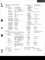
5. PARTS LIST OF P.C. BOARD ASSEMBLIES
AF AMP Assembly(cWK-154)
Note:
SWITCHES
AND TRANSFORME
R
RESISTOR
When ordering resisfors, conuert the
rcsistance ualue into code form, and
then rewrite the part no. as before.
Part No.
Part No.
Symbol & Doscription
Symbol & Description
A S X - |1 5
s1
ASK-172
ASK-171
s2
s3,s4
ATT.577
T2
Remoteslide-switch
{FUNCTION)
Leverswitch (TAPE2)
Leverswitch(SUBSONIC,
LOUDNESS}
Heatertransformer
RSlP Dtrtr J
7\ Rste noo.r
RD%PSNtrO J
2\ Rozesraao.r
RN%PO DOD F
CAPACITORS
Part No.
ACT-130
ACN-070
Symbol & Description
I nozenaranc I
RD%PMtrCD J
cr.c2
c c D s L 1 0 1 J5 0
ACH-224
CEA 22OMsOL
CEA 22OM35L
C E A 4 T O Ml O L
c52, C53
c51
c57
c33, C34
C E A 1 0 1 M1 O L
CEA 1O2MsOL
C E A 1 O l Ms O L
CEA IOIM 35L
CEANL 2R2M 50
c83, C84
c54
c55, C60,C61
c56
c25, C26
C E A N L1 O O M1 6
CEANL R33M 50
CEA 47OMsOL
ccDSL O30C50
ccDsL 100K 500
c3, c4
c75, C76
c77,CA2
c37, C38
c41 , C42
ccDsl 220J 50
ccDsL 470J 50
ccDsl 560J 50
ccDsL 820J 50
ccDSL 181K 500
c7, c8
c5, c6, c21, C22, C29-C32
c 1 5 ,C l 6 , C 2 7 , C 2 8
c35, C36
c43-C46
C E A2 2 1 M1 O L
CKDYF 2232 sO
CKDYX 473M25
CKDYA 1O2J50
coMA 473K 50
c 1 7 ,C 1 8
c39, C40, C89,C90
c78-C81
c85-C88
c47, C48
CKDYA 122J50
coMA 183J50
coMA 563J s0
coMA 683J 50
CEANL R47M 50
c11 , C12
c9, cl0
c23,C24
c 1 3 ,C 1 4
c 1 9 ,C 2 0
Electrofytic 8æO42V
VRl
R65, R66
Variable5O0k(BALANCE)
Wirewound O.22l2Wx2
R74
R102
R63, RAt, R67, R68
R 7 1 , R 7 2 ,R 7 6 ,R 8 0
R 1 1 , R 1 2R
, 1 5 ,R 1 6
R 1 9 ,R 2 0 ,R 5 1 ,R 5 2 ,R 5 5 - R 6 2 ,R 7 0 .
R 7 5 .R 1 0 3 ,R 1 0 4 ,R 1 1 3
R 1 - R 1 0 ,R 1 3 ,R 1 4 .R 1 7 ,R 1 8 ,
R 2 1 - R 5 0 ,R 5 3 ,R 5 4 ,R 6 9 ,R 7 3 ,
R 7 7 - R 7 9 ,R 9 1 - R 9 5 ,R 1 0 5 ,R 1 0 6 ,
R 1 0 8 - R 1t 2
SEMICONDUCTORS
L
t
l\AcG.oo4
C58
Part No.
25C2602
2SA872A
2SA798
2SAg5o-D'
(2SA850-C*l
2SCt735-Dr
{2SC1735-C*)
o1, 02
Q 11 , 0 1 2
07, 08
0 1 7 ,0 1 8
2SC1919
2SC1815
25C1775A
2SCr384
25D880
2SC1885
152076
( 151555)
03, 04
05, 06
09, or0, o13.o14
423, A24
o25
026
D l - D 4 , D 1 8 ,D î 9
* hfe of 01
5-OlSshould
CeramicO.01/15OV
I sooz
I roez
(stBo1-02)
152473
MZ-230
MZ-192
twz-1921
MZ-250
STV3H
AKB.063
AKB-064
L
Q 1 5 .O 1 6
h a v e r h e s a m er a n k
D11-D14
D 9 ,D l O
D5, 06
D20
D17
Dl6
D7, D8
OTHERS
Part No.
J
Symbol & Description
Symbol & Dæcription
Terminal (TAPEI
Terminal {INPUT}
,
I
2. CONTRASTOF MISCELLANEOUSPARTS
o The A marh found on some component parts indicates the importance of the
safety factor of the part. Therefore, when replacing, be sure to use parts of identical
designation.
P.c.BoARDASSEMBLTEs
Part No.
Symbol
D6scriptaon
KU typ6
HB typ€
HE type
AF amplifier assembly
GWK-143
GWK-154
GWK.I54
Tone control assemblY
GWG.137
GWG-144
GWG-144
Switch assembly (A)
Gws-212
GWS-238
GWS-238
Switch assembly (B)
GWS-213
GWS.239
GWS.239
Volume assembly
GWX.457
GWX492
GWX.492
Headphone assembly
GWX.458
GWX493
GWX-493
GWX-494
GWX.494
Fuse assembly
OTHERS
Part No.
Dæcription
Svmbol
KU type
HB type
HE typ€
Front panelassembly
ANB.848
ANB-896
AN8-896
A rr
Powertransformer
ATT-666
ATT-7O5
ATT.7O5
A rur
Fuse(3A)
AEK.l01
Arur
F u s e( 1 A l
AEK4O2
AÉK4O2
2\ruz,:
I rua
as 6
Fuse(2.5A)
AEK4O3
AEK-4O3
acl
Ceramiccapacitor
A
AC socket
Â
Fuse(2.5A)
AEK4O3
Leverswitch(POWER)
ASK-521
ASK-521
AKP.O32
AKP.O44
AKP.O26
AC powercord
ADG€23
ADG{)51
ADG.O41
Screw
ABA.145
A B A . 11 6
A B A . 11 6
o.o11250v
ASK-520
ACG-O01
P A C K I N GA N D F U R N I S H E DP A R T S
Part No.
Symbol
Description
KU type
HB type
HE type
O p e r a t i n gi n s t r u c t i o n s( E N G L I S H )
ARB-366
Operatinginstructions
(GERMAN/FRENCH)
ARD-l48
P a c k i n gc a s e
AHD-749
AHD.776
AHD-776
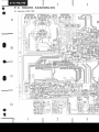
4. P.C. BOARD PATTERNS
A F A M P A s s e m b l y( G W K - 1 5 4 )
^ô^fà
LæC?i
o@
o@
.. rfu^f 2'
o s2
oHNr
C!i CCal
",,00'-
oJ Ërurr'
Ctqol!?
F,100
o@
-
'
q Ë Àut
C40 .1'
?SCl885RqS
o@
/e,o* $]a
rhls
JY)
c 8 c0 0 4 7
ù
R333Ôt
8! 33oX
^
,,-ir:
o i*
o.+
acr !0/'6
#
"lF
!.00P
..
3o:ailtrV$h q,m
/{_T/+\ôq=
4F
r'6P
r!-aû16
;p
o.
:".9'.
4220
0 , 6I 2 . 2 5 0
",+tè#
o
2\
o
o
v) t9
o
18
t"
".ïp
" + hra,Ïf
=!à.t
"i*'
-"t;
ier:'j"r
-"*.':ï'Q "t-1i:lTîtg-rtrg- ,T'* - J3P - ie,l1-'.i'l:'
q.::x
S cr5
"4r00t50 1æ0/rc
I
*G;iq ""- " """ p*.ÉF
R rj 3 9 K
qs -
cB c068
4F
Jj#1
#.
lllsc
F556K
+crl
#;"
>s1:*rE
fu *K
-46
cF 0064
qF
Crô+
ffi;
-!egL
Jl*o*-
û
R,o2?zrw)
:?l
fuilcr oN
iî:r"il",
R 9 51 o o K
C 4ll$
R 2 62 ? X
#
C.6004?
*<
c.7 0041
013
(5r
+
,æ'
TPl
o
@
@@
I
r'"t
q"
;;a
I
I r3
o
o
_@o
I
620
r20
{*..
J""
o
o
L
I
3
Ç
(GWX-a94)
FuseAssembly
o
63
o
64
o61 1 eoo os9
F U rT I A
ZZOV
t
I
F U 1r l A
I
Lt r!H
R650 ?Z(?l)
l-A
Fuz
24OV
062
13'i1
I-
sao
570
I
Ta5a
O
5e:lri*
/rcÉfrô-\
/
@
o\
[_i
J ? s T V 3 N0 o f Y
NOTE:
The only difference between following assemblies in models
SA-5 10/KU, HE and HB types lies in the assembly parts
numbers. All circuit and parts are exactly the same For
P C
board patterns
refer to the seruice manual for
SA-5 10/KU type.
? S A A T 2A . t o t F
T aozz
HE and HB types
Switch assembly (A)
Switch assembly (B)
Volume assembly
H e a d p h o n e as s s e m b l V
o
o
(hg
(!sEV 3SîJ
-1300rÀl
gH uoi .Llncdlc^'lddns u3Mod
u6'sp
NO
-
ljo
6u,tter
€ - v - l j o
NO
çgsl3s?
oçz-7n
-
NO
eto
NO -
*o
-
sslNonoa
llo
frilosen9
llo
-
uo{!u6&p(tttr!'pl
!.qa'JrôrDql'!.d'
,".d-'
-
*-
t s
Fr.r
B3NÔl
!3dv!-1)w-;-
u! tuà@arc)dol
losu'd
or r'P
iln or tB'q
*F-'
v
r",dtu,Énar
?re
Pd'S
41
A
'
€ s
lfo
rild
_
'
xfi!
r.HrLrrdr@ùa
ùoc
!ll
E*no^co
) ul t^rt^
*uonrnà.ro'ælnr*'ronco'É
r&ùo[65
+Moc
fNlusnt
rdJrrt
!'
^6
l9vrtO^
'
*ild
I 54roÀ
'
rl'r
ltl#rr
ui il:"Fl
I
I
suolrtvdvo
(ll lln
w
I {vl'%ar I (5i %lr
Ù u' ÈrblNl
.r.ror tç:
fft
'suofsls3u
.NBlorg!
gç2-2y1o"o
I
ùaelgsz 'zr'zÙ
.3à -l
I ldsr
,..
t:
-'---
I
- " * ïI
-_l
rze '.ù
I
'";;"'
I
------
L--
.'.i;;il^I
^r'o 1oËrloc3mr
iois^e
{t-
L----------)
vç/rl3sz or'50
g6zVsz e'rÙ
clJvT3l.|cs€
sed^l sH onrvaHuo1 snvueYto
o
o
900-^vv
,.
-1
,-r
o 9 € v s z r r ' . ro v g a z t c s z , r . e r o
çÊ1t?szr'.Ê'b vzzgvsz.,.,,o
t----.4;a;.,
.,r.v s3iloHdovfH
puo p asnaq Æo
u srolcnpuoc,tu::'::i::,
sauo anqDluasatda.t arD srollnpuoilwu,'
;i:
gez-sff 9 (v) r,3.v
Hcltms
:: fr:;tt
pu1i"rpu,
r;;:
,r;tr,
EH'aH/ou s-w s