1
f f
o'll
,r*:('
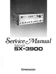
EefvicecVlanual
S T E R E OA M P L I F I E R
S \-Ci,lO
()rrroruEErl'
o This servicemanualis applicableto the KU type.
CONTENTS
I.SPECIFICAT|ONS
2. FRONTPANELFACILITIES
3. DISASSEMBLY
D I A G R A M ,P . C .B O A R D
10. SCHEMATIC
.......3
P A T T E R N SA N D P A R T S L I S T
.....4
....
6
1 0 . 1M i s c e l l a n e a
'.-..'.14
4.PARTSLOCATION
......6
c iagram
1 0 . 2 S c h e m a t iD
15
5. BLOCKDIAGRAM
......8
1 0 . 3 P . C .B o a r dC o n n e c t i o nD i a g r a m
10.4 PartsList of P.C.BoardAssembly
21
6.LEVELDIAGRAM
T.CTRCUITDESCRIPTIONS...
S.ADJUSTMENTS
.......8
...'
9
......10
9 . E X P L O D E D V I E W S A N D P A R T S L I .S.T. . . . . 1 1
1 1 . P A C K I N G.
18
...... 22
(
r
siA-ci1 cl
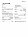
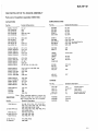
1. SPECIFICATIONS
Semiconductors
FrequencyResponse
P H O N O( RI A A E q u a l i z a t i o n )
lCs
Transistors
Diodes
......
27
18
Amplifier Section
Continup
o0
uw
s eoru t p uotf 4 5 w a t t sp*e rc h a n n e l ,m i n .a, t 8 o h m sf r o m2 0 H e r t zo 2 0 , 0 0 0
H e r t zw i t hn o m o r et h a n
0 . \ 3 % t o t ahla r m o n i c
distortion.
I
Total HarmonicDistortion (20 Hertzto 20,000 Hertz,
I o h m s ,f r o m A U X )
22.5 watts per channel'power
output
. N o m o r et h a n 0 . 0 2 %
IntermodulationDistortion(50 Hertz : 7,000 Hertz= 4 : 1
8 o h m s ,f r o m A U X )
continuousratedpoweroutput . . No more than 0.03%
22.5 watts per channelpoweroutput
No more than O.O2%
DampingFactor (2OHertzto 20.000Hertz,S ohms) . . 50
I nput (Sensitivity/lmpedance)
PHONO
....2.5mV/50kilohms
TUNER
1 5 0 m V / 5 0k i l o h m s
AUX.
....150mV/50kilohms
T A P E P L A Y 1, 2 . .
1 5 0 m V / 5 0k i l o h m s
P h o n oO v e r l o a dL e v e l( T . H . D .O . O 5 o 1
/ o. 0
, 00H2)
PHONO
130mV
O u t p u t( L e v e l )
TAPERECl,2..
... 150mV
Speaker
.... A,B,OFF
20Hzto 20.000H210.3d8
T U N E RA, U X ,T A P EP L A Y1 . 2
13dB
. . 1OHzto 60,000H2
Tone Control
BASS.
..t10dB(100H2)
TREBLE
....t10dB(10,000H2)
SubsonicFilter .
. 15Hz (-6dB/oct)
(
V
o
l
u
m
e
L o u d n e sC
s ontour
c o n t r o ls e ta t - 4 0 d B p o s i t i o n )
, 3 d B( 1 0 , 0 0 0 H 2 )
+
6
d B( 1 0 0 H 2 ) +
.. ..
H u m a n d N o i s e( l H F , s h o r t - c i r c u i t e A
d,network)
PHONO
. . .82dB
TUNER,AUX,TAPEPLA
1 ,Y2 . . ,
... IOOdB
Miscellaneous
P o w e rR e q u i r e m e n t s
AC 120V,60H2
PowerConsumption
...100W(UL)
Dimensions
. 4 2 O ( W xl 9 4 ( H ) x 3 4 7 ( D )m m
1 6 - 9 / 1 6 ( Wx )3 - 1 1 l 1 6 ( Hx) 1 3 - 1 1 / 1 6 ( D
i n)
W e i g h t( w i t h o u tp a c k a g e )
6 . 9 k g( 1 5 l b 3 o z )
FurnishedParts
Operatinglnstructions
........1
NOTE:
Specifications and the design subject to possible modifications
without notice due to improvements.
*
Measured pursuant to the Federal Trade Commission,s Trade
Regulation rule on Power Output Claims for Amplifiers.
2 . F R O N TP A N E L F A C I L I T I E S
O POWERSWITCH
Set this switch to ON to supply power to the amplifier.
There will be a short delay when it is set to ON. because
the muting circuit has been actuated to suppressthe
unpleasantnoise that is sometimesgeneratedwhen the
power is on and off .
@ P O W E RM E T E R
This meter allows you to readout the rated power level
on the fluorescentdisplay tube when speakerswith a
nominal impedanceof 8 ohms are connectedto the
a m p li f i e r ' ss p e a k etre r m i n a l s .
INDICATORS
@ FUNCTTON
@ S P C E T E RS E L E C T O R
Usethis selectorto selectthe speakersystem.
O F F : S o u n dn o t o b t a i n e df r o m s p e a k e r s .
A:
Sound obtained from speakersconnectedto the
A s p e a k etre r m i n a l s .
B:
Sound obtained from speakersconnectedto the
B s p e a k etre r m i n a l s .
@ B A S SA N D T R E B L EC O N T R O L S
Use these controls to adjust the bass and the treble.
lf you set the tone switchto ON and turn the basscontrol
to right from its center position, you will be able to
e m p h a s i z et h e s o u n d i n t h e l o w - f r e q u e n c yr a n g e .C o n versely, turning the bass control to the left from the
c e n t e rp o s i t i o n y, o u w i l l a t t e n u a t et h e s o u n d .
You can use the treble control to adjustthe soundin the
range.
high-frequency
T h e T U N E R , P H O N O ,T A P E , A U X f u n c t i o n i n d i c a t o r s
light up in accordancewith the positionof the function
selector.
@ F U N C T I O NS E L E C T O R
Use this selectorto selectthe programsource.When set.
the function indicatorabovethe meter panelcorrespondr ill lightup.
i n g t o t h e p o s i t i o no f t h e f u n c t i o ns e l e c t ow
t o b r o a d c a so
t sn a t u n e r
T U N E R : S e t h e r ew h e n l i s t e n i n g
t o t h e T U N E Rj a c k s .
connected
( T h eT U N E R f u n c t i o ni n d i c a t o rl i g h t su p . )
P H O N O : S e t h e r e w h e n p l a y i n gr e c o r d so n a t u r n t a b l e
connectedto the PHONOjacks.
( T h eP H O N Of u n c t i o ni n d i c a t o rl i g h t su p . )
T A P E 1 : S e t h e r e w h e n p l a y i n gt a p e so n t h e t a p ed e c k
connectedto the TAPE 1 jacks.
(TheTAPE function indicatorlightsup.)
AUX:
Set here when listeningto a programsource
w h i c h i s c o n n e c t e tdo t h e A U X j a c k s .
( T h eA U X f u n c t i o ni n d i c a t o rl i g h t su p . )
r
sA-Ci1cl
i
I
i
O volurvrEcoNTRoL
Use this control to adjustthe output levelto the speakers
and headphones.
Turn it clockwiseto increase
the output
l e v e l .N o s o u n dw i l l b e h e a r di f y o u s e t i t t o , , 0 . , '
JA cK
@ nCRopHoNE
Plug the headphones into this jack when you want to
listen through your stereo headphones.
NOTE:
Set the speakerselector to OFF when listening only with headphones.
S WT T C H
€ ) su e s o N t c F TL T E R
I
I
When this switch is set to the 'l 5Hz position,the subsonic
filter with a cut-off frequencyof 15Hz is actuated.The
subsonicfilter servesto attenuatefrequencieslower than
15Hz in a 6dB/oct slope. lt is therefore effective in
suppressing
ultra-low-frequency
noise which is generated
by record warp and other causes.You cannot actually
hear this noise but it is a factor in the generationof
intermodulation distortion and it may damage your
speakersystem. Set this switch to the 1SHz position
during recordplay for the besteffect.
@ rorueswtrcH
f'
r
t-
Set this switch to ON when adjustingthe bassand treble
controls.When set to the upper (OFF) position,the tone
control circuits are disengaged
and frequencyresponseis
flat. This function is convenientfor checkingphono cartridge and speaker tone quality and listening room
acoustics.
@ powentNDtcAToR
When the power switch is set to ON this lamp lights up,
indicating
t h e a m p l i fi e r i s t u r n e do n .
swtrcH
@ LouolrrEss
When listeningto a performancewith the volumecontrol
turned down, set this switch to ON and the bassand
treblewill be accentuated.
W h e nt h e v o l u m e i s l o w , t h e h u m a ne a r f i n d s i t h a r d e r
to hear the bassand treble than when the volumeis high.
The loudnessswitch is thus designedto compensatefor
this deficiency.By setting it to ON, the bassand treble
come throughmuch more stronglyand the soundtakeson
a punchevenwhen the volumecontrol is turneddown.
@ rnpe 2 swrTcH
Set this switch to the ON position when monitoring a tape
performance on a tape deck which you have connected to
t h e T A P E 2 j a c k so r w h e n m o n i t o r i n g a r e c o r d i n g .
NOTE:
Set the switch to the upper (OFF) position when tistening to
records or broadcasts, etc. selected by the function selector.
@ BalarucEcoNTRoL
Use this control to balancethe volume of the left and
r i g h t c h a n n e l sl.f t h e s o u n da p p e a r tso b e l o u d e ro n t h e
r i g h t , i t m e a n st h a t t h e v o l u m eo f t h e r i g h t c h a n n e li s
higher.Turn the balancecontrol to the left and adjust.
Conversely,if the soundappearsto be louderon the left,
it meansthat the volume of the left channel is higher.
Therefore, turn the balancecontrol to the right and
adjust.
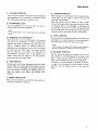
3. DISASSEMBLY
Bottom Plate
Removethe six screws O.
Bonnet Case
Removethe four screws o .
Front Panel
Removethe four screws e .
\o..oo/o'
Bonnet case
Front panel
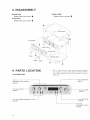
4. PARTS LOCATION
o The !i, marh found on some component parts indicates
the importance of the safety factor of the part. There'
fore, when replacing, be sure to use parts of identical
designation.
FrontPanelView
m
(t
.J!g!r.-
K n o b( B A L A N C E I
AAB.223
Leverknob
( L O U D N E S ST,A P E2 )
AAD.2OO
6
siA-610
Front View with Front Panel Removed
F l u o r e s c e n ti n d i c a t o r t u b e
AAV-O06
V a r i a b l er e s i s t o r( B A S S .T R E B L E )
ACT-127
Slide rotary switch
(FUNCTION)
A S X - I1 3
sl ide rota ry r*i t"tr -------]-=---.'
(SPEAKERS)
ASE-oo3
:
I"
| ,, ll
'!'tlr '
I
'l
o L:---Variable
€
tu
r e s i s t o r( V O L U M E )
"
I
I
L e v e rs w i t c h ( P O W E R ]
V a r i a b l er e s i s t o r( B A L A N C E )
ASK.520
Headphones
.jack
AKN-023
f
ACT-130
-Lever
s w i t c h( T A P E2 )
ASK.172
L e v e rs w i t c h ( S U B S O N I C ,T O N E )
A S K - 17 1
Leverswitch ( LOUDN ESS)
ASK-171
Top View with Bonnet Removed
rl|r
j
Powertransformer
ATT-667
Switch assembly
GWS-215
Switch assembly
GWS-216
Volume assembly
GWX459
t-
t
A F a m p l i f i e ra s s e m b l y
GWK.144
H e a d p h o n e sa s s e m b l y
GWX460
Tonecontrolassembly
GWG-138
RearPanelView
I AC socker
AKP.O32
1i Power code
ADG-023
T e r m i n a l{ I N P U T )
AK8.064
T e r m i n a l( T A P E 1 )
AKB-063
Strein reliel
AEC-327
Terminal(SPEAKERS)
AKE-051
5. BLOCK DIAGRAM
swtrcHEs:
st Fu&trox luxEP-M-raPEI-AUX
ON - 6F
32
fAPE?
t3
ouoi€ls
ox - gll
54
Su6oirt(t5Hrl
Ox - 6
55
SPEAXERS
O'F-A-'
s6
&s€R
ox -!Il
se
ioilE
or _lI!
6 . L EV E L DI A G RA M
l}.tlJ"roo't
AUX /TUNER
15OmV
xeai pnone(eo)
siA-61
n
7 . C I R C U I TD E S C R I P T I O N S
EqualizerAmplifier
The 54,-610 features a 3-stage direct-coupled
equalizer amplifier for greater reduction of noise
and distortion.
Besides the use of an ultra low-noise transistor
(25C26O2) in the first stage, the adoption of low
impedance input resistance and equalizer circuit
has contributed to an S/N ratio of at least 82dB
(at 2.5mV input, IHF-A).
rl
I
!f'
f,
cl
Power Amplifier
This all stage direct-coupled pure complementaly SEPP circuit features a current mirror load
differential amplifier in the first stage, and incorporates the tone control circuit in the NFB loop.
Although the incorporation of the tone control
circuits in the power amplifier stage reduces the
number of elements that the signal has to pass
through, and thereby further reduces noise, distortion, and cost, the power stage does require a
higher gain and a higher degtee of stability. In the
SA-610, this high gain and high stability are
achieved by a cunent mirror load differential
amplifier in the first stage and by the use of a
constant current circuit for the load of the predriver stage. Furthermore, the tendency for the
pre-driver stage capacitance impedance load to
cause deterioration in the high end frequency
responseis suppressedby inserting a capacitor (C)
between the emitter of the pre-driver stage (Q2)
and the baseof the constant current circuit (Q1) as
shown in Fig. 7-1. At frequencies where the
reactance of this capacitor may be ignored, the
push-pull action of Ql and Q2 servesto counteract
the high end frequency response deterioration.
The power amplifier stage is a complementary
2-stage' Darlington connection, resulting in an
output power rating of 45W + 45W (8Q, 20Hz2OkHz\, harmonic distortion of less than O.O37o
(20H2
20kHz at rated output), and output
power bandwidth of 5Hz - 50kHz (0.O3% THD).
Certainly a superb performance for an amplifier
of this classis obtained.
/
/. Constant
circuit
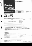
Protection Circuit
Besides protecting the speakers if a DC voltage
should happen to appear at the power amplifier
stage outputs, this circuit also mutes the signal
path when the power switch is turned on and off
(SeeFig. 7-2).
If for any reason a DC voltage (in excess of
about tbV) should happen to appear in the output
of the power amplifier stage, it is detected immediately by either Q23 or q24. qn is turned on by
a positive voltage, and Q24 by a negative voltage. In
either case,Q25 is also turned off, thereby opening
the relay contact to disconnect the power amplifier
stage from the speakers. ,
The muting action when the power switch is
turned on is achieved by delaying the rise of the
Q25 base potential by means of the R95/C77 time
constant circuit. When the power switch is turned
on, C77 is charged up via R95, thereby increasing
the voltage across both ends of this capacitor.
When this voltage exceeds the zener voltage of the
D15 zener diode, Q25 is biased in the forward
direction, and is thereby tumed on to close the
relay contact.
When the power switch is turned off., C77
dischargesrapidly via D18, resulting in Q25 being
turned off, thereby opening the relay contact.
L CH SP OUT
R CH SP OUT
Fig. 7-2 Frotectioncircuit
current
o,,u.,..r"n"
iF
)to
\Pre-driver
staga
stage
Fig. 7-1 Pre-driver
I
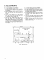
8. ADJUSTMENTS
8 . 1 I D L E C U R R E N TA D J U S T M E N T
1. Set the SPEAKERS selector to the A position,
and connect an 8Q resistor to the speaker output terminals.
2. Turn the VOLUME control down to minimum
level, turn the power on, and wait about 10
minutes.
3. Connect a DC voltmeter to the TP terminals
(Lch; TP4 and TP3, Rch; TP2 and TP1) of the
AF Amplifier Assembly (GWK-144).
4. Check that the voltage between TP4 and TP3
(Lch) lies within the DC 4mV-50mV range
then make a similar check for the Rch (between
TP2 and TP1). If the voltage is less than 4mV,
cut jumper wire A (Lch), and jumper wire B
(Rch). If the voltage exceeds 70mV, check for
circuit failure.
8.2 OUTPUT INDICATOR ADJUSTMENT
1. Set the TONE CONTROL to the center position.
2. Set the SPEAKERS selector to the A position,
and connect an 8O resistor and AC voltmeter to
the speaker output terminals.
3. Set the FUNCTION switch to the AUX position,
and apply a 7kHz, 150mV signal to the AUX
terminals.
4. Adjust the VOLUME control so that the voltage
on the output terminals (SPEAKERS) read 9V
(AC).
5. Adjust VR1 (Lch) and VR2 (Rch) of the indicator assembly so that the output power
indicator read 10 watts.
AF Amplifier Assembly
(GWK-144)
@ Jumperwire A
Jumper
--l
@vR2
vR1
F.L MeterAssemblye
F i g .8 - 1 A d j u s t m e npt o i n t
10
sA-61
r
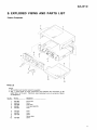
9 . E X P L O D E DV I E W S A N D P A R T S L I S T
ExteriorComponent
fa
'-:'\
I
.t4
f-'
f,
PartsList
NOTE:
c Parts without part number cannot be supplied.
o The A marh found on some component parts indicates the importance of the
safety factor of the part. Therefore, when replacing, be sure to use parts of id.entical designation.
Part No.
Description
1.
2.
3.
4.
5.
ANE.269
ABA-079
AAD.2OO
AN8.847
AAB.222
Bonnet case
Screw
Lever knob
Front panel assembly
Knob
6.
7.
8.
9.
10.
AAB.223
AAB.221
ABA-186
Knob
Knob
Screw
Bottom plate
Screw
Key No.
1;r
AB4-066
.4
cl
InteriorComponent
lK'?
il
32
- - 36,2ssl-
ffu..Q
Nf-,
ro '9;i,
w
38
34
um
;l _^s-
44
Y'2o
29
30
Y
siA-cil
tt^
o
PartsList
Part No.
Description
l\ 1.
2.
3.
4.
4rT-667
A s.
AsK-s2o
Power transformer
Wire clip
Frame
Switch assembly
Lever switch
26.
27.
28.
29.
30.
ASK-I71
ASK-172
ACT-130
AKB-063
AKB-064
Lever switch
Lever switch
Variable resistor
Terminal
Terminal
A e.
Acc-ool
7.
8.
9.
10.
GWX460
GWG-I38
AWV{07
Capacitor
Headphones assembly
Tone control assembly
F.L. assembly
Cushion
31.
32.
33.
34.
35.
AEC-672
ABA-107
484-066
ABA-234
Frame
Foot assembly
Screw
Screw
Screw
LED socket
Switch assembly
Volume assembly
Cushion rubber
LED
36.
37.
38.
39.
40.
A84-026
M45-O86
871-004
ABE-005
ABA-240
Screw
1t spacer
Nut 9@
Washer
Screw
Panel stay
Heat sink
AC socket
Rear panel
Power code
4't.
42.
43.
44.
45.
ABA-198
Screw
Remote wire
AEC-352
Nylon rivet
P . C . B .h o l d e r
I nsulator spacer
Strein relief
Terminal
Terminal(GND)
Fuse
AF amplifier assembly
46.
47.
48.
2SA1108/A/Oor R T r a n s i s t o rt h f e s h o u l d h a v et h e
25C2588/A/OorR T r a n s i s t o rJ s a m er a n k
Screw
ABA-145
Key No.
|'^
xr-
11.
12.
13.
14.
15.
16.
17.
A rg.
19.
Azo.
21 .
22.
23.
Azc.
25.
GWS-215
GWS-216
GWX-459
AEL-320
AKP-032
ADG-o23
AEC-327
AKE-O51
AEK-Ioo
GWK-I44
Key No.
Part No.
AEC-488
Description
T,
13
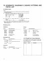
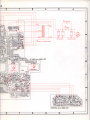
1 O .S C H E M A T I CD I A G R A M . P . C . B O A R D
P A T T E R N SA N D
PARTS LIST
1 0 . 1M I S C E L L A N E A
NOTE:
When ordering resistors,first conuert resistance ualues into code form as shown in
the following examples.
Ex. 1 When there are 2 effectiue digits (any digit apart from 0), such as 560 ohm
and 47h ohm (tolerance is shown by J = SVo,and K = 10Vo).
RDVTPSE@IilJ
...
56Oa-56x10t-561
RD|/tPSAABJ
...'
47ha-47x103-473
R N 2 H@ E E K
...
.._
6.Sa-1RS
...8SrP@[0@/(
...
ta-010
c
When there are 3 effective digits (such as in high precision metal film
resistors).
' . RN7ISrB tr@gm ,F
5621. .
562 x 10'
5.62ha
o The A mark found on sotne component parts indicates the importance of the
safety factor of the part. Therefore, when replacing, be sure to use parts of
identical designation.
Ex. 2
Miscellaneous
Parts
ASSEMBLIES
Part No.
OTHERS
Symbol & Description
GWK-144
GWG-138
GWS-215
GWS-216
GWX459
AF amplifier assembly
Tone control assembly
Switch assembly
Switch assembly
Volume assembly
GWX460
AWV-007
Headphones assembly
F.L. assembly
Part No.
A 4TT-667
7\ ner-t oo
ASK-520
A nrpoez
Symbol & Description
T1
F1
SB
A nocozs
Powertransformer
Fuse
Leverswitch (POWER)
AC socket
Power code
ANB-847
AKE451
Front panel assembly
Terminal(SPEAKERS)
SEMICONDUCTORS
List of ChangedPartsfor FactoryModification
Part No.
Symbol & Description
2sA1108/A/o 021,422\
2sc2s88/i;5 019,o2o I
.j
orR
AEL.32O
ntesnoura
havethesamerank
Symbol
D1 LED
CAPACITOR
Part No.
A ACGOO1
List of changedparts informationwill be furnishedwhenever necessaryand you are requestedto amend parts
numberin this partslist.
Symbol & Description
C1
Capacitor 0.01/250V
Part No.
Description
1
3
2
DIAGRAM
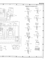
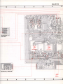
1 0 . 2S C H E M A T I C
o':
o"t'' (1/2)
GW-K-144
l---ot
A
|IIp-]]*_|..."::.F I
IIIl'"::'""-#"I
$"il | Lry
I l_UI
l-r'
it---1 "'
i "'o"I E--l I @ H'l
lffil
{.i''#,,ffiff
l
.AUX
J"'"1
i"*,'''rt5i
illlF'-._'*
1\Jn*'ffii
l:;;
l
::iHEi-Tf
l{----l
l-:::
llll l _H ll
I
B
(
[4Eg
l:#i
i-iI";+
II
':n
'l
s2:' aPEz-
REc
f
l
r 3l
too47/25
.l'l
i
17 |
|
1
ffiNrRoLAss.v(2,2,G
llll---.-.
I| """-"
i| t*41+.t_|dr{::::,:^f{..",","u"1*,,oI
||Hl fd h
l , J
L-,=:i
c
l
Ll-I
*HE-{
l
l^'- ftzzzu
r
-
S WI T C HE S :
S
Z
TUNER -
FUNCTION
s t,7:
:
T
A
p
E
?
O
N
-
O
PHONO F
F
TAPE I -
AUX
-
r
I
53
:
LOUDNESS
ON -
OFF
I
54
:
SUBSONIC (15 Hz )
ON -
OFF
I
S P E A K E R S
O F F - A - B
56
.
POWER
ON _
OFF
58
:
TONE
ON -
OFF
5 5 :
T h e u n d e r l i n e di n d i c a t e st h e s w i t c h p o s i t i o n .
I
I
L
D
1
2
3
-l
l
S W I T C HA s s ' y
-
GWS -?15
_
I
R5l
2.2k
D3
rs2075
c39
o.ot/
500
I
t-
'-^
i--T--i
c67 27p I
f
; ??'?t I
---"J"-l F ttr-J
'o*
56
asE-oo3
u'tt*'
SB%,,
l
tok
cto
o.00r2
Rrol
6 . 2t
c68
27o
nea'6zr YFl,i., I
-
-
-
82P
ol
ts2076
2SC19r4A-G
!*
l'"
l"F
c6l
RzO lgk
Q2
roo,/so
RzZ
tO
HA r2 0 t O
C48
_^.-J?rJ
d
) L A s s ' y( 2 / 2 1 G W G- 1 3 8
,r.3i.
*^^-J
R92
ilOk
R52
I
0l(POWER)
az6 2scrass-R
"ro A
I
vr
aAv-oo6
o r rc e z s o
AIC58
4A - O.OllACtso
T2
A T T -5 7 7
ot7
AF AMP Ass'y (2/21
GWK-144
lt/zwl
AC POWER
CORO
aDG-o23
A
A rro
820(t/2w)
oizso
\
c e z ' 6 . ot
I
acr25
L___
J
EiA-61cI
7
8
9
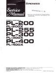
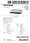
Appearance of Transistorsand fCs
2SA912
.---
-l.
2 S C18 8 5
F
O
__1__fr_
I
l l 3
l'.-.lL-J
r* J "Jl L_j
| *r------ll
) )
a:u
l<#ll
]llnt-t
ll_--
l
l--
suffix===O
otNo--B^
'veNo
h"-]1tt/ !ilf-rvpe
)
u"tru"-*ffii)-n'E
/l\
"o
4[L\
il
-
g_l
_l
d%&;
+48?q-E
+l
2SC19144
2SA979
r y p e " " $-
--
'/50
A
rvpe..-fl${
i-3
t
2SC1815
R ?
I
> ' 2k
-liI
{At20t0
=-----r
i Ef l r l , ' l
Lot No-S;a/
trr"-"$
^"7
l !
f l l l =l l m . l
illl*llttl.l-
lt il
islll'lll.l-
B
2SC2602
,^\
2 S C2 2 7 5
I
r l H l
I
''nlg
2SC
2SA985
I
n*=-+*LfT-rvpe
No
sflK
!\
3r!
2SD7
12
2SA1 108A
\
fr'"ru"-fu
2SC2588A
Type
*"-__N+\-\,\_\
n,.ffi
ll lt (J-
LotNoffin'.
--Lot
uu\i
No
su ll
u
c
s
T A7';::
2 S C13 8 ;
n"-$ii
/m
!\
r-otruo-{Ul+-rvpe
No
ru
\--===-J
2sc,::r ^
?
- - ruo-{
r'
rype
p--.--LotNo
D
t-hre
)fr1=--c,.{{i,
il u
surTrx
il
I
E
U\
7
8
I
17
10.3P.C.BOARDCONNECTIONDIAGRAM
Lch
Rch
HEADPHONE
Arr'y
(GWX460I
FL Asr'y (AWV.007I
SWITCHAs'y
(cws-216)
EtA-Ci1 cl
HEADPHONE
As'y
(cwx460l
2s A11o,AlA/
VOLUMEArr'y (GWX459)
I
lo
-t
ACl 20V
6OHz
SWITCHEO
L - - - - - - _ - - _ J
UNSWITCHEO
T1
POWER TFIANSFORMER
AF AMPAr'y (GWK-1441
CONTROLAr'y (GWG-I38)
;
t
*
siA-61
Cl
10.4PARTSLISTOF P.C.BOARDASSEMBLY
PartsList of AmplifierAssembly(GWK-144)
SEMICONDUCTORS
CAPACITORS
Symbol & Description
Part No.
Part No.
Symbol & Description
c c D s L 1 0 1 J5 0
CEA 1O2MsOL
C E A 2 2 1 M3 5 L
C E A 1 O l Ms O L
C E A 1 0 1 M3 5 L
c't,c2
c54
c59
c60, c61, css
c56,C77
25C2602
2SC1919
2SC1815
25A979
25C17754
01,02
03, 04
05, 06
07, 08
09, 010
C E A 1 0 1 M1 O L
C E A4 7 1 M6 L
CEA 47OMsOL
C E A2 2 1 M1 O L
C E A 4 T O M1 O L
c83, C84
c49
c51
c 1 8 ,C 1 7
c33, C34
2SA912
2SC1885
2SC 2275-0
2SA 985-O
2SC1914A
0 1I , 0 1 2
0 1 3 ,0 1 4 ,0 2 6
C E A N LO l O M5 0
C E A N L2 R 2 M5 0
C E A N Ll O O M1 6
C E A N LR 3 3 M5 0
C E A N LR 7 4 M5 0
c71,c72
c25, C26
c3, c4
c75,C76
c19,C20
2SC1384
25D712
o2s
o27
D l - D 4 ,D l 8
ccDsl mrc 50
ccDSL100K500
ccDSL 220J 50
ccDSL 330J50
ccDSL 470J 50
c37, C38
c41, C42
c7,c8
c86, C87
c5, c6, c21-22,C29-C32
1S2076
( 1S1555)
152473
STV3H
10F-2
(srBo1-02)
GP-25D
MZ-130
D11-D14
Dl5
ccDsL 560J 50
ccDSL 820J 50
c c D S L 1 5 1 K5 0 0
C K D Y F1 0 3 25 0
cKDYF 1032 500
c 1 5 , C 1 6 ,C 2 7 , C 2 AC, 8 8 ,C 8 5
c35, C36
c43-C46
c50
c39, C40
coMA 473K 50
CKDYX 473M25
coMA 122J50
coMA 183J50
coMA 563J 50
c47, C48
c78-C81
c11, C12
c9, cl0
c23, C24
coMA 683J 50
ACG-017
ACG-004
ACH-215
c 1 3 ,C l 4
c62
c58
c52, C53
Note:
RESISTORS
Part No.
RD!/rPMoDtrJ
A noy. PMFoooJ
RNTcPOootrJ
ARD% PsFotroJ
RD% PSOOOJ
A RS t poool
A ncruozo
When ordering resistors, convert the
resistance ualue into code form, and
then rewrite the part no, as before.
Symbol & Description
0 1 5 , 0 1 6 l h f es h o u t d h a v e t h e
01 7, 01 8 J samerank
o23,O24
D5, D6
D7, D8
D9,DlO
{wz-130}
MZ-270
D16
MZ-I92
lwz-l921
D17
OTHERS
Part No.
ACT-130
ASK-171
ASK-172
A S X . I1 5
Inrr-szz
AKB.063
AK8-064
ASR-033
Symbol & Description
VR1
s3,s4,s7
s2
s1
T2
Variable resistor
Lever switch
Lever switch
Remote slide switch
Heater transformer
Terminal
Terminal
Relay
R1-R8. R13, R14, R17, R18,R21R50, R53, R54, R69, R70, R77-R79,
R 9 1 - R 9 3 , R 9 5 ,R 1 0 5 - R 1 0 8
R19, R20, R51, R52, R55-R62. R73,
R 7 5 ,R 1 0 3 ,R l 0 4
B g - R 1 2 ,R 1 5 ,R 1 6
R63, R64, R76, R80
R67, R68, R71,R72
R74, R94, R102
R65, R66
21
PartsList of Tone ControlAssembly(GWG-I3b)
CAPACITORS
Part No.
Part No.
Symbol & Description
coMA 303J50
coMA 124K50
cosA 270KsO
CQMA122K50
coMA 562K50
Note:
RESISTORS
Part No.
ACT-127
tr qJ
RDT4PMD
PartsList of SwitchAssembly(GWS-216)
c63, C64
c65, C66
c67, C68
c69, C70
c73, C74
When ordering resistors, conuert the
resistance ualue into code form, and
then rewrite the part no. as before.
Symbol & Description
VR3. VR4
Variableresistor
R 8 1 - R 9 0 ,R 1 0 1 ,R 1 0 0
A S X - 1| 3
Part No.
Symbol & Description
ASE.OO3
R S l P3 3 1 J
RDlzrPM563J
55
Sliderotaryswitch(SPEAKERS)
R96, R97
R98, R99
11. PACKING
PartsList
Key No.
1.
2.
3.
Part No.
Description
ARB.351
AHD.754
AH4.239
Operating instructions
Packing case
Side pad
56 Slide rotary switch (FUNCTION)
PartsList of VolumeAssembly(GWX-4S9)
Part No.
ACV-184
Symbol & Description
VR2
V a r i a b l e r e s i s t o r( V O L U M E )
PartsList of Headphones
Assembly(GWX-460)
Part No.
AKN-023
PartsList of Switch Assembly(cWS-215)
Symbol & Description
Symbol & Description
H e a d p h o n e sj a c k
0
I
)
a
PICINEEFI
ELECTFICINIC
CCIFIPCIFIATICIN
4-1, Mesuno 1-chome, Mesuno-ku. Tokyo 'l 53, Japen
U.a. FEIfVEEFI
EI-ECTFICDNICE
CCIFIPCIF|ATICIN
E|5 Oxfond Dnive, Moon€chie,
U.S.A.
New Jereey O7O7\
(El.rFlCtFE
FGIilCEFI
eECTFlClillC
N.\/. Luithagen-Heven
9,2O3O
Antwe.p,
Elelgium
FCIwCEF
A|J3TFIALIA
El-CTFlCtI\llC|l
FTY. LtEl. 17A-1A4
Eloundenv F|oad. Eltreeside. Victonia 3'l 95, Augtnelie
(aRT'478€)
EAiT-
. a7q
PFhted
in
Jeoan