1
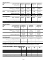
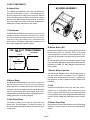
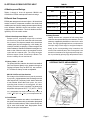
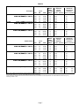
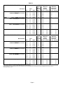
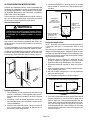
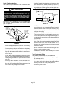
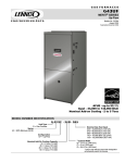
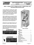
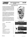
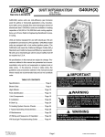
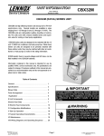
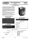
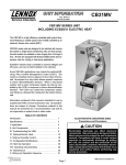
CB26UH
CBX26UH
Corp. 0527−L10
Service Literature
CB26UH &CBX26UH Series
The CB26UH, and CBX26UH are high efficiency blower coils.
Several models are available in sizes ranging from 1-1/2
through 5 tons (5.3 through 17.6 kW). The CBX26UH is designed for R−410A refrigerant and the CB26UH is designed for
R−22 refrigerant. The units are up flow / horizontal that can be
field converted to down flow applications. The units come with
a factory installed check and expansion valve for cooling or
heat pump applications.
CB26UH and CBX26UH series units are designed to be
matched with the 13SEER air conditioner and heat pump line,
but can be matched with other air conditioners or heat pumps
as noted in the rating information. See Engineering Handbook.
Electric heat, in several kW sizes, can be field installed in the
CB26UH and CBX26UH cabinets.
Information contained in this manual is intended for use by experienced HVAC service technicians only. All specifications are
subject to change. Procedures outlined in this manual are presented as a recommendation only and do not supersede or replace local or state codes.
IMPORTANT
Improper installation, adjustment, alteration, service
or maintenance can cause property damage, personal injury or loss of life. Installation and service must
be performed by a qualified installer or service
agency.
WARNING
Electric shock hazard. Can cause injury
or death. Before attempting to perform
any service or maintenance, turn the
electrical power to unit OFF at disconnect switch(es). Unit may have multiple
power supplies.
Page 1
Table of Contents
Specifications / Electrical Data . . . . . .
Blower Data . . . . . . . . . . . . . . . . . . . . . .
I Application . . . . . . . . . . . . . . . . . . . . . .
II Unit Components . . . . . . . . . . . . . . . .
III Optional Electric Heat . . . . . . . . . . .
IV Configuration Modification . . . . . . .
V Start Up . . . . . . . . . . . . . . . . . . . . . . . .
VI Typical Operating Characteristics .
VII Maintenance . . . . . . . . . . . . . . . . . . .
VIII Wiring Diagrams . . . . . . . . . . . . . . .
NO TAG
Page 3
Page 4
Page 5
Page 6
Page 10
Page 13
Page 14
Page 14
Page 15
© 2005 Lennox Industries Inc.
Litho U.S.A.
SPECIFICATIONS
Model Number (R−22)
Model Number (R−410A)
CB26UH−018
CBX26UH−018
CB26UH−024
CBX26UH−024
CB26UH−030
CBX26UH−030
CB26UH−036
CBX26UH−036
1.5
2
2.5
3
Suction/Vapor line (o.d.) − in. (mm) sweat
3/4 (19)
3/4 (19)
7/8 (22.2)
7/8 (22.2)
Liquid line (o.d.) − in. (mm) sweat
3/8 (9.5)
3/8 (9.5)
3/8 (9.5)
3/8 (9.5)
Condensate − in. (mm) fpt
(2) 3/4 (19)
(2) 3/4 (19)
(2) 3/4 (19)
(2) 3/4 (19)
Wheel nominal diameter x width − in. (mm)
10 x 6
(254 x 152)
10 x 6
(254 x 152)
11 x 8
(279 x 203)
11 x 8
(279 x 203)
1/4 (187)
1/4 (187)
1/4 (187)
1/3 (249)
16 x 20 x 1
(406 x 508 x 25)
16 x 20 x 1
(406 x 508 x 25)
18 x 20 x 1
(457 x 508 x 25)
18 x 20 x 1
(457 x 508 x 25)
208/240V
208/240V
208/240V
208/240V
15
15
15
15
1.5
1.5
1.6
1.8
129 (58)
131 (59)
148 (67)
148 (67)
General
D t
Data
Nominal tonnage
Connections
Blower
Blower motor output − hp (W)
1 Filters
Size of filter − in. (mm)
ELECTRICAL DATA
Voltage − 1 phase (60 hz)
2 Maximum
overcurrent protection (unit only)
3 Minimum
circuit ampacity (unit only)
Shipping Data −1 package − lbs. (kg)
SPECIFICATIONS
Model Number (R−22)
Model Number (R−410A)
CB26UH−042
CBX26UH−042
CB26UH−048
CBX26UH−048
CB26UH−060
CBX26UH−060
3.5
4
5
Suction/Vapor line (o.d.) − in. (mm) sweat
7/8 (22.2)
7/8 (22.2)
7/8 (22.2)
Liquid line (o.d.) − in. (mm) sweat
3/8 (9.5)
3/8 (9.5)
3/8 (9.5)
Condensate − in. (mm) fpt
(2) 3/4 (19)
(2) 3/4 (19)
(2) 3/4 (19)
Wheel nominal diameter x width − in. (mm)
11 x 8
(279 x 203)
11 x 8
(279 x 203)
11−1/2 x 9
(292 x 229)
1/3 (249)
1/2 (373)
1/2 (373)
18 x 25 x 1
(457 x 635 x 25)
18 x 25 x 1
(457 x 635 x 25)
18 x 25 x 1
(457 x 635 x 25)
208/240V
208/240V
208/240V
General
D t
Data
Nominal tonnage
Connections
Blower
Blower motor output − hp (W)
1 Filters
Size of filter − in. (mm)
ELECTRICAL DATA
Voltage − 1 phase (60 hz)
2 Maximum
overcurrent protection (unit only)
3 Minimum
circuit ampacity (unit only)
Shipping Data −1 package − lbs. (kg)
1 Filter is not furnished and must be field supplied.
2 HACR type circuit breaker or fuse.
3 Refer to National or Canadian Electrical Code
15
15
15
1.9
2.6
4.1
172 (78)
177 (80)
190 (86)
manual to determine wire, fuse and disconnect size requirements. Use wires suitable for at least 167°F (75_C).
OPTIONAL ACCESSORIES − MUST BE ORDERED EXTRA
−018
−024
−030
−036
−042
−048
−060
Circuit Breaker Cover Kit
93M85
93M85
93M85
93M85
Down−Flow Conversion Kit
12W61
12W61
12W61
12W61
Model
Horizontal Support Frame Kit
56J18
56J18
56J18
56J18
Side Return Unit Stand (Up−Flow Only)
45K32
45K32
45K32
45K32
Single Point Power Source Control Box (for Electric Heat)
21H39
21H39
21H39
21H39
Wall Hanging Bracket Kit (Up−Flow Only)
45K30
45K30
45K30
45K30
Page 2
BLOWER DATA
CB(X)26UH−018 BLOWER PERFORMANCE
Air Volume at
External Static
Specific Blower Taps
Pressure
High
Low
in. w.g.
Pa
cfm
L/s
cfm
L/s
.10
25
1020
460
755
340
.20
CB(X)26UH−024 BLOWER PERFORMANCE
Air Volume at
External Static
Specific Blower Taps
Pressure
High
Low
in. w.g.
Pa
cfm
L/s
cfm
L/s
.10
25
1040
470
1000
455
50
960
435
715
325
.20
50
980
445
940
425
.30
75
885
400
675
305
.40
100
800
365
625
285
.30
75
905
410
870
395
.40
100
815
370
785
355
.50
125
690
315
570
.60
150
525
250
500
260
.50
125
705
320
680
310
235
.60
150
535
250
530
250
NOTE − All air data measured external to unit with dry coil and 1 inch non−pleated air
filter in place.
Electric heaters have no appreciable air resistance.
NOTE − All air data measured external to unit with dry coil and 1 inch non−pleated air
filter in place.
Electric heaters have no appreciable air resistance.
CB(X)26UH−030 BLOWER PERFORMANCE
Air Volume at
External Static
Specific Blower Taps
Pressure
High
Low
in. w.g.
Pa
cfm
L/s
cfm
L/s
.10
25
1350
610
1145
520
CB(X)26UH−036 BLOWER PERFORMANCE
Air Volume at
External Static
Specific Blower Taps
Pressure
High
Low
in. w.g.
Pa
cfm
L/s
cfm
L/s
.10
25
1560
705
1405
635
.20
50
1290
585
1090
495
.20
50
1480
670
1340
610
.30
75
1225
555
1030
465
.40
100
1150
520
960
435
.30
75
1390
630
1270
575
.40
100
1290
585
1185
540
.50
125
1065
485
875
.60
125
965
455
775
395
.50
125
1170
530
1090
495
365
.60
150
1015
480
975
460
NOTE − All air data measured external to unit with dry coil and 1 inch non−pleated air
filter in place.
Electric heaters have no appreciable air resistance.
NOTE − All air data measured external to unit with dry coil and 1 inch non−pleated air
filter in place.
Electric heaters have no appreciable air resistance.
CB(X)26UH−042 BLOWER PERFORMANCE
Air Volume at
External Static
Specific Blower Taps
Pressure
High
Low
in. w.g.
Pa
cfm
L/s
cfm
L/s
.10
25
1940
880
1785
810
CB(X)26UH−048 BLOWER PERFORMANCE
Air Volume at
External Static
Specific Blower Taps
Pressure
High
Low
in. w.g.
Pa
cfm
L/s
cfm
L/s
.10
25
1945
880
1870
850
.20
50
1845
835
1705
775
.20
50
1860
845
1790
810
.30
75
1745
790
1615
730
.40
100
1630
740
1515
685
.30
75
1765
800
1700
770
.40
100
1660
155
1600
725
.50
125
1495
680
1400
.60
150
1330
630
1265
635
.50
125
1540
700
1485
675
595
.60
150
1395
660
1350
635
NOTE − All air data measured external to unit with dry coil and 1 inch non−pleated air
filter in place.
Electric heaters have no appreciable air resistance.
NOTE − All air data measured external to unit with dry coil and 1 inch non−pleated air
filter in place.
Electric heaters have no appreciable air resistance.
CB(X)26UH−060 BLOWER PERFORMANCE
Air Volume at
External Static
Specific Blower Taps
Pressure
High
Low
in. w.g.
Pa
cfm
L/s
cfm
L/s
.10
25
2160
980
2075
940
.20
50
2065
935
1985
900
.30
75
1960
890
1885
855
.40
100
1845
835
1775
805
.50
125
1710
775
1645
745
.60
150
1550
730
1495
705
NOTE − All air data measured external to unit with dry coil and 1 inch non−pleated air
filter in place.
Electric heaters have no appreciable air resistance.
Page 3
CB26UH & CBX26UH PARTS ARRANGEMENT
ELECTRIC HEAT SECTION
(plate to be removed if installed)
CONTROL BOX
BLOWER COMPARTMENT
COIL
HORIZONTAL DRAIN PAN
EXPANSION VALVE
(R−22 or R−410A)
UPFLOW DRAIN PAN
FIGURE 1
ELECTROSTATIC DISCHARGE (ESD)
Precautions and Procedures
I−APPLICATION
All major blower coil components must be matched according to Lennox recommendations for the unit to be
covered under warranty. Refer to the Engineering Handbook
for approved system matchups. A misapplied system will
cause erratic operation and can result in early unit failure. The
units come with factory installed check and expansion valve for
all applications. The TXV valve has been installed internally for
a cleaner installation and is accessible if required.
CAUTION
Electrostatic discharge can affect electronic
components. Take precautions during unit installation and service to protect the unit’s electronic
controls. Precautions will help to avoid control
exposure to electrostatic discharge by putting
the unit, the control and the technician at the
same electrostatic potential. Neutralize electrostatic charge by touching hand and all tools on an
unpainted unit surface before performing any
service procedure.
Page 4
II−UNIT COMPONENTS
BLOWER ASSEMBLY
A−Control Box
The CB26UH and CBX26UH control box is located above
the blower section shown in figure 1. Line voltage and electric heat connections are made in the control box. Optional
electric heat fits through an opening located in the center of
the control box. When electric heat is not used, cover plates
cover the opening. The electric heat control arrangement is
detailed in the electric heat section of this manual.
1−Transformer
All CB26UH and CBX26UH series units use a single line
voltage to 24VAC transformer mounted in the control
box. The transformer supplies power to the control circuits in the indoor and outdoor unit. Transformers are
rated at 40VA. 208/240VAC single phase transformers use
two primary voltage taps as shown in figure 2.
FIGURE 3
B−Blower Motor (B3)
208 / 240 VOLT TRANSFORMER
PRIMARY
CB26UH and CBX26UH units use single phase direct drive
blower motors with a run capacitor. Figure 3 shows the
parts arrangement. All motors have two speed taps. Typically, the high speed tap is energized during normal operation.
SECONDARY
ORANGE
BLUE
240 VOLTS
RED
All units are factory wired for the high blower speed for heat
pump and cooling applications with or without electric heat. No
field wiring is required. The wiring diagrams show factory set
blower speeds.
208 VOLTS
YELLOW
BLACK
1−Blower Motor Capacitor
FIGURE 2
All CB26UH and CBX26UH series units use single phase direct drive motors with a run capacitor. The run capacitor is
mounted on the blower housing. See figure 3. Capacitor ratings are shown on side of capacitor and indoor blower motor
nameplate.
2−Blower Relay
All CB26UH and CBX26UH units use a DPST relay to energize the blower motor. The relay coil is energized by
blower demand from indoor thermostat. When the coil is
energized, a set of N.O. contacts closes to energize the blower
motor on cooling speed. When de−energized, a set of N.C.
contacts allows the electric heat relay to energize the blower on
heating speed (refer to unit wiring diagram).
C−Coil
CB26UH and CBX26UH units have dual slab coils arranged in an A" configuration. Each coil has two or three
rows of copper tubes fitted with ripple−edged aluminum
fins. An expansion valve, feeds multiple parallel circuits through
the coils. The coil is designed to easily slide out of the unit cabinet.
3−Time Delay Relay
The blower time delay is a 24 volt N.O. relay wired to the
blower relay. See unit diagram. The delay is between 10
and 60 seconds and delays the blower on and off time in the
cooling cycle.
D−Plastic Drain Pans
Drain pans are provided and installed on the CB26UH and
CBX26UH, The drain pans are made from fiberglass filled
plastic.
Page 5
TABLE 1
III−OPTIONAL ECB26 ELECTRIC HEAT
ECB29 CIRCUIT BREAKERS
A−Matchups and Ratings
UNIT
CB1
AMPS
CB2
AMPS
CB3
AMPS
ECB26-5CB-1 (P)
30 AMP
−−−
−−−
ECB26-7CB-1 (P)
45 AMP
−−−
−−−
ECB2610CB-1 (P)
60 AMP
−−−
−−−
ECB26-15CB-1 (P)
60 AMP
30 AMP
−−−
ECB26-20CB-1 (P)
60 AMP
60 AMP
−−−
Tables 2 through 4 show all approved CB26UH and
CBX26UH to ECB26 matchups and electrical ratings.
B−Electric Heat Components
ECB26 parts arrangement is shown in figure 4. All electric heat
sections consist of components mounted to the electric heat
vestibule panel and electric heating elements exposed directly
to the airstream. 208/230V electric heat sections may be
equipped with circuit breakers. The circuit breakers are designated by CB in the model number.
1−Electric Heat Sequencer Relays 1 and 2
Relays are N.O. sequencer relays with a resistive
element for a coil and a bi-metal disk which actuates
the contacts. The relays are located on the electric heat
vestibule panel and are energized by a 24V heating demand (W1 and W2) via jack/plug 2. When energized, the
internal resistance heats the bi-metal disk causing the contacts to close. When the relay is de-energized, the disk
cools and the contacts open. The relays energize
different stages of heat, as well as the blower. The
blower is always first on and last off.
4−Heating Elements
Heating elements are composed of helix wound bare
nichrome wire exposed directly to the airstream. The elements are supported by insulators mounted to the wire
frame. For single phase applications, one element is
used per stage. Each stage is energized independently by the corresponding relay located on the
electric heat vestibule panel. Once energized, heat
transfer is instantaneous. High temperature protection is provided by primary high temperature limits.
ECB26−7, -7CB, -10, -10CB 208/230
VESTIBULE PARTS ARRANGEMENT
2−Primary Limits 1, 2, 3 & 4
The primary limits are located on the electric heat vestibule
panel and exposed directly to the airstream through an
opening in the panel. They are SPST N.C. auto −reset limits. The limits are factory set and not adjustable.
HEATING ELEMENTS
ELECTRIC HEAT
SEQUENCER
1&2
208/230 Volt Electric Heat Sections
PRIMARY LIMITS
1, 2, 3 & 4
Each stage of the 208/230 electric heat is protected
by a primary high temperature limit. Each stage uses the
same style of limit. The primary limit is wired in series with
a heat element. When either limit opens, the corresponding heat element is de-energized. All other
heating elements remain energized. The primary high
temperature limit opens at 150_F + 5_F (65.5_C + 2.8_C)
on a temperature rise and automatically resets at
110_F + 9_F (43.3_C + 5.0_C) on a temperature fall.
3−Circuit Breaker
Line voltage connections are made to circuit breakers in
the electric heat sections with circuit breakers (designated
by CB in the model numbers). Table 1 shows the amp rating for each circuit breaker used. Single phase electric
heat uses two pole circuit breakers.
CIRCUIT BREAKER
FIGURE 4
Page 6
TABLE 2
CB(X)26UH−018 / CB(X)26UH−024
SINGLE PHASE ELECTRIC HEAT
Description
5 kW
ECB26−5 ((99M64)) Terminal Block
ECB26−5CB
ECB26
5CB (99M65) Ci
Circuit
it B
Breaker
k
7.5 kW
ECB26−7 ((99M66)) Terminal Block
ECB26−7CB
ECB26
7CB (99M67) Ci
Circuit
it B
Breaker
k
10 kW
ECB26−10 ((99M68)) Terminal Block
ECB26−10CB
ECB26
10CB (99M69) Ci
Circuit
it B
Breaker
k
Volt
208
220
230
240
208
220
230
240
208
220
230
240
Input
kW
3.8
4.2
4.6
5.0
5.6
6.3
6.9
7.5
7.5
8.4
9.2
10.0
1 Btuh
12,800
14,300
15,700
17,100
19,200
21500
23500
25,600
25,600
28,700
31,400
34,100
SINGLE PHASE ELECTRIC HEAT
CB(X)26UH−030
Model Number
5 kW
ECB26−5 ((99M64)) Terminal Block
ECB26 5CB (99M65) Ci
it B
k
ECB26−5CB
Circuit
Breaker
7.5 kW
ECB26−7 ((99M66)) Terminal Block
ECB26−7CB
ECB26
7CB (99M67) Ci
Circuit
it B
Breaker
k
10 kW
ECB26−10 ((99M68)) Terminal Block
ECB26−10CB
ECB26
10CB (99M69) Ci
Circuit
it B
Breaker
k
15 kW
ECB26−15CB (99M70)
(
) Circuit Breaker
2 Minimum
3 Maximum
Blower
Circuit
Overcurrent
Motor
Ampacity
Protection
Full Load
Amps
A
Circuit 1 Circuit 2 Circuit 1 Circuit 2
1.5
19.5
−−−
30
−−−
1.4
22.2
−−−
30
−−−
1.4
22.2
−−−
30
−−−
1.4
22.2
−−−
30
−−−
1.5
28.6
−−−
45
−−−
1.4
32.7
−−−
45
−−−
1.4
32.7
−−−
45
−−−
1.4
32.7
−−−
45
−−−
1.5
37.6
−−−
60
−−−
1.4
43.1
−−−
60
−−−
1.4
43.1
−−−
60
−−−
1.4
43.1
−−−
60
−−−
Volt
208
220
230
240
208
220
230
240
208
220
230
240
208
220
230
240
Input
kW
3.8
4.2
4.6
5.0
5.6
6.3
6.9
7.5
7.5
8.4
9.2
10.0
11.3
12.6
13.5
15.0
1 Btuh
12,800
14,300
15,700
17,100
19,200
21500
23500
25,600
25,600
28,700
31,400
34,100
38,400
43,000
47,000
51,200
2 Minimum
3 Maximum
Blower
Circuit
Overcurrent
Motor
Ampacity
Protection
Full Load
Amps
A
Circuit 1 Circuit 2 Circuit 1 Circuit 2
1.6
19.6
−−−
30
−−−
1.5
22.3
−−−
30
−−−
1.5
22.3
−−−
30
−−−
1.5
22.3
−−−
30
−−−
1.6
28.7
−−−
45
−−−
1.5
32.8
−−−
45
−−−
1.5
32.8
−−−
45
−−−
1.5
32.8
−−−
45
−−−
1.6
37.7
−−−
60
−−−
1.5
43.2
−−−
60
−−−
1.5
43.2
−−−
60
−−−
1.5
43.2
−−−
60
−−−
1.6
37.7
18.1
60
30
1.5
43.2
20.8
60
30
1.5
43.2
20.8
60
30
1.5
43.2
20.8
60
30
NOTE − Circuit 1 Minimum Circuit Ampacity includes the Blower Motor Full Load Amps.
1 Electric heater capacity only − does not include additional blower motor heat capacity.
2 Refer to National or Canadian Electrical Code manual to determine wire, fuse and disconnect size requirements. Use wires suitable for at least 167°F (75_C).
3 HACR type breaker or fuse.
Page 7
TABLE 3
SINGLE PHASE ELECTRIC HEAT
CB(X)26UH−036
Description
5 kW
ECB26−5 ((99M64)) Terminal Block
ECB26−5CB
C 26 C (99
(99M65)
6 )C
Circuit Breaker
7.5 kW
ECB26−7 ((99M66)) Terminal Block
ECB26−7CB
C
C ((99M67)) C
Circuit Breaker
10 kW
ECB26−10 ((99M68)) Terminal Block
ECB26−10CB
C
C ((99M69)) C
Circuit Breaker
15 kW
ECB26−15CB (99M70)
(
) Circuit Breaker
Volt
208
220
230
240
208
220
230
240
208
220
230
240
208
220
230
240
Input
kW
3.8
4.2
4.6
5.0
5.6
6.3
6.9
7.5
7.5
8.4
9.2
10.0
11.3
12.6
13.5
15.0
1 Btuh
12,800
14,300
15,700
17,100
19,200
21500
23500
25,600
25,600
28,700
31,400
34,100
38,400
43,000
47,000
51,200
SINGLE PHASE ELECTRIC HEAT
CB(X)26UH−042
Model Number
5 kW
ECB26−5 ((99M64)) Terminal Block
ECB26−5CB
C 26 C (99
(99M65)
6 )C
Circuit Breaker
7.5 kW
ECB26−7 ((99M66)) Terminal Block
ECB26−7CB
C 26 C (99
(99M67)
6 )C
Circuit Breaker
10 kW
ECB26−10 ((99M68)) Terminal Block
ECB26−10CB
C 26 10C (99
(99M69)
69) C
Circuit Breaker
15 kW
ECB26−15CB (99M70)
(
) Circuit Breaker
2 Minimum
3 Maximum
Blower
Circuit
Overcurrent
Motor
Ampacity
Protection
Full Load
Amps
A
Circuit 1 Circuit 2 Circuit 1 Circuit 2
1.8
19.8
−−−
30
−−−
1.7
22.5
−−−
30
−−−
1.7
22.5
−−−
30
−−−
1.7
22.5
−−−
30
−−−
1.8
28.9
−−−
45
−−−
1.7
33.0
−−−
45
−−−
1.7
33.0
−−−
45
−−−
1.7
33.0
−−−
45
−−−
1.8
37.9
−−−
60
−−−
1.7
43.4
−−−
60
−−−
1.7
43.4
−−−
60
−−−
1.7
43.4
−−−
60
−−−
1.8
37.9
18.1
60
30
1.7
43.4
20.8
60
30
1.7
43.4
20.8
60
30
1.7
43.4
20.8
60
30
Volt
208
220
230
240
208
220
230
240
208
220
230
240
208
220
230
240
Input
kW
3.8
4.2
4.6
5.0
5.6
6.3
6.9
7.5
7.5
8.4
9.2
10.0
11.3
12.6
13.5
15.0
1 Btuh
12,800
14,300
15,700
17,100
19,200
21500
23500
25,600
25,600
28,700
31,400
34,100
38,400
43,000
47,000
51,200
2 Minimum
3 Maximum
Blower
Circuit
Overcurrent
Motor
Ampacity
Protection
Full Load
Amps
A
Circuit 1 Circuit 2 Circuit 1 Circuit 2
1.9
20.0
−−−
30
−−−
1.8
22.6
−−−
30
−−−
1.8
22.6
−−−
30
−−−
1.8
22.6
−−−
30
−−−
1.9
29.0
−−−
45
−−−
1.8
33.1
−−−
45
−−−
1.8
33.1
−−−
45
−−−
1.8
33.1
−−−
45
−−−
1.9
38.0
−−−
60
−−−
1.8
43.5
−−−
60
−−−
1.8
43.5
−−−
60
−−−
1.8
43.5
−−−
60
−−−
1.9
38.0
18.1
60
30
1.8
43.5
20.8
60
30
1.8
43.5
20.8
60
30
1.8
43.5
20.8
60
30
NOTE − Circuit 1 Minimum Circuit Ampacity includes the Blower Motor Full Load Amps.
1 Electric heater capacity only − does not include additional blower motor heat capacity.
2 Refer to National or Canadian Electrical Code manual to determine wire, fuse and disconnect size requirements. Use wires suitable for at least 167°F (75_C).
3 HACR type breaker or fuse.
Page 8
TABLE 4
CB(X)26UH−048
SINGLE PHASE ELECTRIC HEAT
Description
5 kW
ECB26−5 ((99M64)) Terminal Block
ECB26−5CB
C 26 C (99
(99M65)
6 )C
Circuit Breaker
7.5 kW
ECB26−7 ((99M66)) Terminal Block
ECB26−7CB
C
C ((99M67)) C
Circuit Breaker
10 kW
ECB26−10 ((99M68)) Terminal Block
ECB26−10CB
C
C ((99M69)) C
Circuit Breaker
15 kW
ECB26−15CB (99M70)
(
) Circuit Breaker
20 kW
ECB26−20CB (99M71)
(
) Circuit Breaker
Volt
208
220
230
240
208
220
230
240
208
220
230
240
208
220
230
240
208
220
230
240
Input
kW
3.8
4.2
4.6
5.0
5.6
6.3
6.9
7.5
7.5
8.4
9.2
10.0
11.3
12.6
13.5
15.0
15.0
16.8
18.4
20.0
1 Btuh
12,800
14,300
15,700
17,100
19,200
21500
23500
25,600
25,600
28,700
31,400
34,100
38,400
43,000
47,000
51,200
51,200
57,300
62,700
68,200
SINGLE PHASE ELECTRIC HEAT
CB(X)26UH−060
Model Number
5 kW
ECB26−5 ((99M64)) Terminal Block
ECB26−5CB
C
C ((99M65)) C
Circuit Breaker
7.5 kW
ECB26−7 ((99M66)) Terminal Block
C 26 C (99
6 )C
ECB26−7CB
(99M67)
Circuit Breaker
10 kW
ECB26−10 ((99M68)) Terminal Block
C 26 10C (99
69) C
ECB26−10CB
(99M69)
Circuit Breaker
15 kW
ECB26−15CB (99M70)
(
) Circuit Breaker
20 kW
ECB26−20CB (99M71)
(
) Circuit Breaker
2 Minimum
3 Maximum
Blower
Circuit
Overcurrent
Motor
Ampacity
Protection
Full Load
Amps
A
Circuit 1 Circuit 2 Circuit 1 Circuit 2
2.6
20.7
−−−
30
−−−
2.5
23.3
−−−
30
−−−
2.5
23.3
−−−
30
−−−
2.5
23.3
−−−
30
−−−
2.6
29.7
−−−
45
−−−
2.5
33.8
−−−
45
−−−
2.5
33.8
−−−
45
−−−
2.5
33.8
−−−
45
−−−
2.6
38.7
−−−
60
−−−
2.5
44.2
−−−
60
−−−
2.5
44.2
−−−
60
−−−
2.5
44.2
−−−
60
−−−
2.6
38.7
18.1
60
30
2.5
44.2
20.8
60
30
2.5
44.2
20.8
60
30
2.5
44.2
20.8
60
30
2.6
38.7
36.1
60
60
2.5
44.2
41.7
60
60
2.5
44.2
41.7
60
60
2.5
44.2
41.7
60
60
Volt
Input
1 Btuh
kW
208
220
230
240
208
220
230
240
208
220
230
240
208
220
230
240
208
220
230
240
3.8
4.2
4.6
5.0
5.6
6.3
6.9
7.5
7.5
8.4
9.2
10.0
11.3
12.6
13.5
15.0
15.0
16.8
18.4
20.0
12,800
14,300
15,700
17,100
19,200
21500
23500
25,600
25,600
28,700
31,400
34,100
38,400
43,000
47,000
51,200
51,200
57,300
62,700
68,200
2 Minimum
3 Maximum
Blower
Motor
Circuit
Overcurrent
Full Load
Ampacity
Protection
Amps
(240V) Circuit 1 Circuit 2 Circuit 1 Circuit 2
4.1
22.2
−−−
30
−−−
3.9
24.7
−−−
30
−−−
3.9
24.7
−−−
30
−−−
3.9
24.7
−−−
30
−−−
4.1
31.2
−−−
45
−−−
3.9
35.2
−−−
45
−−−
3.9
35.2
−−−
45
−−−
3.9
35.2
−−−
45
−−−
4.1
40.2
−−−
60
−−−
3.9
45.6
−−−
60
−−−
3.9
45.6
−−−
60
−−−
3.9
45.6
−−−
60
−−−
4.1
40.2
18.1
60
30
3.9
45.6
20.8
60
30
3.9
45.6
20.8
60
30
3.9
45.6
20.8
60
30
4.1
40.2
36.1
60
60
3.9
45.6
41.7
60
60
3.9
45.6
41.7
60
60
3.9
45.6
41.7
60
60
NOTE − Circuit 1 Minimum Circuit Ampacity includes the Blower Motor Full Load Amps.
1 Electric heater capacity only − does not include additional blower motor heat capacity.
2 Refer to National or Canadian Electrical Code manual to determine wire, fuse and disconnect size requirements. Use wires suitable for at least 167°F (75_C).
3 HACR type breaker or fuse.
Page 9
IV−CONFIGURATION MODIFICATIONS
CB26UH and CBX26UHunits are factory−assembled and
configured for installation in upflow or horizontal left−hand
air discharge applications. A kit is available to convert units
for downflow applications. See OPTIONAL ACCESSORIES at the front of this manual.
4. Install units that have no return air plenum on a stand
that is at least 14" from the floor. This will allow proper
air return.
Upflow Configuration
If the unit needs to be modified from its original configuration, use the following procedures. All procedures assume
the unit has not been modified from the factory.
HORIZONTAL
DRAIN PAN
(Remove for best
upflow performance)
General Information
WARNING
Improper installation, adjustment, alteration, service
or maintenance can cause property damage, personal injury or loss of life. Installation and service must
be performed by a qualified installer or service
agency.
Each unit consists of a blower assembly, refrigerant coil,
and controls, in an insulated galvanized steel factory finished enclosure. Knockouts are provided for electrical wiring entrance.
For ease in installation, it is best to make any necessary coil
configuration changes before setting air handler in place.
If a filter is to be installed at the air handler, a filter rack must
be formed using factory−supplied flanges. Lay the unit on its
back and pry out the filter rack tabs as shown in figure 5.
Filter Rack Tabs
HORIZONTAL
DRAIN
CONNECTIONS
(Both sides; Not
used)
UPFLOW
DRAIN PAN
UPFLOW DRAIN
CONNECTIONS
(Both sides; use
on side or other)
FIGURE 6
Horizontal Applications
NOTE − When the unit is installed in horizontal applications,
a secondary drain pan is recommended. Refer to local
codes.
This unit may be installed in left−hand or right−hand air discharge horizontal applications. Adequate support must be
provided to ensure cabinet integrity. Ensure that there is adequate room to remove service and access panels if installing in the horizontal position.
1. Determine whether left-hand or right-hand air discharge is required. If right-hand is required, perform
Right−Hand Discharge Modification. See next page.
2. Determine knockouts required for drain line connections.
3. With access door removed, knock out drain line opening for installing drain lines.
4. Set unit so that it is sloped (up to 1/4 inch) toward the
drain pan end of the unit.
5. The horizontal configuration is shown in figure 7.
Left−Hand Air Discharge Configuration
AIR
FLOW
FIGURE 5
Drains
Upflow Application
1. The air handler must be supported on the bottom only
and set on solid floor or field-supplied support frame.
Securely attach the air handler to the floor or support
frame.
2. If installing a unit in an upflow application, remove the
horizontal drain pan; it is not required in upflow air discharge installations.
3. Place the unit in desired location. Set unit so that it is
level. Connect return and supply air plenums as required using sheet metal screws.
KNOCKOUT
LEFT-HAND DRAINS
FIGURE 7
6. If the unit is suspended, the entire length of the cabinet
must be supported. If you use a chain or strap, use a
piece of angle iron or sheet metal attached to the unit
(either above or below) to support the length of the cabinet. Use securing screws no longer than 1/2 inch to
avoid damaging the coil or filter. See figure 8. Use sheet
metal screws to connect the return and supply air plenums as required.
Page 10
Suspending Horizontal Unit
ANGLE IRON OR
SHEET METAL
Field Modification for Right−Hand Discharge
REMOVE
DRAIN PAN
FROM HERE
THEN...
Electrical Inlet Clearance 4 in. (102 mm)
1/2 in. Screws max.
REINSTALL
PAN HERE
REMOVE 2
SCREWS AND
BP BRACKET
FROM HERE
THEN...
AIR
FLOW
ROTATE BP
BRACKET AND
REINSTALL
FRONT VIEW
REMOVE
COIL SUPPORT
BRACKET
FROM HERE
THEN...
END VIEW
FIGURE 8
REINSTALL
BRACKET
HERE
IMPORTANT
When removing the coil, there is possible danger of
equipment damage and personal injury. Be careful
when removing the coil assembly from a unit
installed in right− or left−hand applications. The coil
may tip into the drain pan once it is clear of the cabinet. Support the coil when removing it.
BRACKET
SHOWN AS
SHIPPED
Right−Hand Air Discharge Modification
BRACKET
SHOWN FOR
RIGHT HAND
DISCHARGE
Right−Hand Air Discharge Configuration
DETAIL A
AIR
FLOW
DETAIL B
FIGURE 10
Drains
KNOCKOUT
RIGHT-HAND DRAINS
FIGURE 9
For horizontal right−hand air discharge, the following field
modifications are required.
1. Remove and set aside blower and coil access covers.
2. Remove the coil support bracket (see detail A, figure
10).
3. Remove coil assembly, bottom drain pan and horizontal drain pan as one assembly from the air handler.
4. Remove the drain plugs from back of horizontal drain
pan and reinstall in the front holes.
5. Remove two screws and blowoff prevention bracket
(BP BRACKET" in figure 10). Rotate the bracket 180º
and reinstall using the same screws.
6. Move horizontal drain pan to the opposite side of the
coil. Plugged drain holes will now be toward the back
of the unit (see figure 11).
7. Re−install modified coil/drain pan assembly in air handler in the same orientation as before.
8. Install the coil support bracket on the opposite side of
the air handler (detail B, figure 10)..
Page 11
Right-Hand Discharge Drain Plug Location
PLUGGED
END
ORIGINAL
PLUG
LOCATION
COIL
ASSEMBLY
OPEN END FOR
CONDENSATION
DRAIN
NEW PLUG
LOCATION
FIGURE 11
Install Condensate Drain
The air handler is provided with ¾" NPT condensate drain
connections.
4. Install a 3" trap in both the primary and secondary drain
lines as close to the unit as practical (see figure 13).
Make sure the top of the trap is below the connection
to the drain pan to allow complete drainage of the pan.
IMPORTANT
Typical Condensate Drain Connection
(Secondary Drain Not Shown)
A field−fabricated secondary drain pan, with a drain
pipe to the outside of the building, is required in all
installations over a finished living space or in any
area that may be damaged by overflow from the main
drain pan. In some localities, local codes may require
an secondary drain pan for any horizontal installation.
AIR
HANDLER
DRAIN CONNECTION
ANTI−SIPHON
AIR VENT
DRAIN LINE
1" Min.
DRAIN PAN
12" Max.
Make sure the unit is sloped (up to 1/4 inch) so that the drain
pan will empty completely without water standing in the
pan. See figure 12.
THIS CORNER
SHOULD BE
5/8I (+/- 1/8I)
HIGHER THAN
DRAIN CORNER
THIS CORNER
SHOULD BE
5/8I (+/- 1/8I)
HIGHER THAN
DRAIN CORNER
DRAIN CORNER
FIGURE 12
1. Remove the appropriate drain knockouts. If necessary,
remove the indoor coil assembly from the cabinet.
2. Connect primary drain line connection to the primary
drain pan connection. The primary drain connection is
flush with the bottom of the inside of the pan. Secondary connection is raised above the bottom of the inside of the pan.
NOTE − When making drain fitting connections to the
drain pan, hand tighten the fitting and use a sealant.
Overtightening the fittings can split connections on the
drain pan.
3. Secondary drain connections, if used, should be connected to a separate drainage system. Run the secondary drain line to a place where the occupant would be
sure to notice any drainage from the drain.
3" Min.
DRAIN TRAP
FIGURE 13
NOTE − Horizontal runs over 15 ft. long must also have
an antisiphon air vent (standpipe) installed ahead of
the horizontal run (See figure 13). An extremely long
horizontal run may require an oversized drain line to
eliminate air trapping.
NOTE − Do not operate air handler without a drain trap.
The condensate drain is on the negative pressure side
of the blower; therefore, air being pulled through the
condensate line will prevent positive drainage without
a proper trap.
5. Route the drain line to the outside or to an appropriate
drain. Drain lines must be installed so they do not block
service access to the front of the air handler. A 24"
clearance is required for filter, coil, or blower removal
and service access.
NOTE − Check local codes before connecting the drain
line to an existing drainage system.
6. Insulate the drain lines where sweating could cause
water damage.
Test Condensate Drain
Test the drain pan and drain line after installation:
1. Pour several quarts of water into drain pan, enough to
fill drain trap and line.
2. Check to make sure the drain pan is draining completely, no leaks are found in drain line fittings, and water is
draining from the end of the primary drain line.
3. Correct any leaks found.
Page 12
setting far enough below room temperature to bring on
the compressor. Compressor will start and cycle on demand from the thermostat. After a 30 second time delay
(approximate) the indoor blower will energize.
V−START-UP − OPERATION
A−Preliminary and Seasonal Checks
1− Make sure the unit is installed in accordance with the
installation instructions.
2− Inspect electrical wiring, both field and factory installed for
loose connections. Tighten as required.
3− Check voltage at disconnect switch. Voltage must be within range listed on the nameplate. If not, consult the power
company and have voltage condition corrected before starting unit.
2− The refrigerant circuit is charged with R−22 or R−410
refrigerant. See condensing unit rating plate for correct charge amount.
3− Refer to the correct condensing unit service manual for
more information.
C−Heating Start-Up
4− Check to ensure that refrigerant lines are in good
condition and pipe insulation is intact.
1− Set the fan switch to AUTO or ON and move the system selection switch to HEAT. Adjust the thermostat
setting above room temperature.
5− Inspect condition of condensate drain pan and piping assembly. Disassemble and clean seasonally.
2− The indoor blower and the electric heat will stage on based
on sequencer timing.
D−Safety or Emergency Shutdown
B−Cooling Start-Up
Turn off unit power at circuit breaker.
NOTE−The following is a generalized procedure and
does not apply to all thermostat control systems. Electronic
thermostat control systems may operate differently.
E−Extended Period Shutdown
1− Set fan switch to AUTO or ON and move the system
selection switch to COOL. Adjust the thermostat to a
Turn off thermostat or set to UNOCCUPIED" mode. Turn
off power to unit. All access panels and covers must be in
place and secured. The condensate assembly should be
clean and dry for extended period shutdown.
Page 13
VI−TYPICAL OPERATING CHARACTERISTICS
A−Blower Operation and Adjustment
NOTE− The following is a generalized procedure and
does not apply to all thermostat controls.
1− Blower operation is dependent on thermostat control system.
2− Generally, blower operation is set at thermostat subbase fan switch. With fan switch in ON position, blower
operates continuously. With fan switch in AUTO position, blower cycles with demand.
3− In all cases, blower and entire unit will be off when the
system switch is in OFF position.
B−External Static Pressure
1− Measure tap locations as shown in figure 14.
STATIC PRESSURE TEST
MANOMETER
SUPPLY
1. Disconnect all power supplies.
2. Remove the air handler access panel.
3. Locate pin number 2 on the blower relay. Two black
wires are connected to this terminal pin. One connects
to pin number 5 on the blower relay, one connects to an
inline splice connecting to a red or blue wire.
4. Remove the wire going to the 4−pin blower motor connector from the splice.
5. Connect the blower lead [Red (LO), Black (HI)] onto the
splice from the 4−pin blower motor connector.
NOTE − Unused blower speed taps are factory−covered with plastic caps. Remove this cap from the desired blower speed tap and replace it over the factory−
set blower tap.
6. Replace all panels.
7. Reconnect power.
VII−MAINTENANCE
WARNING
RETURN
Disconnect power before performing any
maintenance.
UNIT SHOWN IN
HORIZONTAL DISCHARGE LEFT POSITION
FIGURE 14
2− Punch a 1/4" (6mm) diameter hole in supply and return
air plenums. Insert manometer hose flush with inside
edge of hole or insulation. Seal around the hose with
permagum. Connect the zero end of the manometer to
the discharge (supply) side of the system. On ducted
systems, connect the other end of manometer to the return duct as above. For systems with non−ducted returns, leave the other end of the manometer open to the
atmosphere.
3− With only the blower motor running and the evaporator coil dry, observe the manometer reading. Adjust
blower motor speed to deliver the air desired according to the job requirements.
At the beginning of each heating/cooling season, the system should be checked as follows:
A−Filters
NOTE− Filter access panel must be in place during unit
operation, or excessive warm air may enter the unit resulting in water blow−off problems.
TABLE 5
Unit Air Filter Size Chart
Model
18 / 24
30 / 36
42 / 48 / 60
Filter Size
16" x 20"
18" x 20"
18" x 25"
5− Seal around the hole when the check is complete.
To remove filter, remove 1/4" head screws holding the filter panel in place. Slide filter out of the guides on either
side of cabinet, insert new filter and replace panel. Filters should be inspected monthly and must be replaced
when dirty to ensure proper blower coil operation. See
table 5 for replacement filter sizes.
C−Blower Speed Taps
B−Supply Air Blower
4− For best air performance external static pressure
drop must not exceed 0.5" W.C. (1.2 kPa). Refer to
blower data tables for cfm and external static.
Change Blower Speed
WARNING
Electric shock hazard! − Disconnect all
power supplies before servicing.
Replace all parts and panels before
operating.
Failure to do so can result in death or
electrical shock.
1- Check and clean blower wheel.
2- Motors are prelubricated for extended life; no further lubrication is required.
C−Electrical
1- Check all wiring for loose connections.
2- Check circuit breaker located in unit control box.
3- Check for correct voltage at unit (unit operating).
4- Check amp-draw on blower motor.
5- Check to see that heat (if applicable) is operating.
Page 14
VIII−WIRING DIAGRAMS AND SEQUENCE OF OPERATIONS
6
SEQUENCER 2
12 BK
12 BK
L1B
3
1 12 BK
GND
220
208/240
VOLTAGE
BY
OTHERS
12 Y
12 BK
12 BK
L2A
7
12 Y
SEQUENCER 1
CIRCUIT BREAKER 1 (OPT)
L1A
LIMIT SWITCH 4
HE3
18 BU
L2B
HE4
5
ELECTRIC HEAT − 2ND STAGE
18 BK
12 BK LIMIT SWITCH 3
4
CIRCUIT BREAKER 2 (OPT)
3
ELECTRIC HEAT − 1ST STAGE
LIMIT SWITCH 1
5
4
12 BK
3
1
12 BK
4
HE1
HE2
LIMIT SWITCH 2
12 Y
2
3
4
1
2
3
4
6−PIN
PLUG
5
6
5
6
18 BK
W2
1
18 W
W1
TRANSFORMER
24
18 BU
C
18 G
G
18 R
R
3
24V
H
18 BU
H
8
18 G
18 BU
C
18 BU
14 BK
208V
240V
18 R
14 R
14 Y L2
14 BK L1
6
COM
3
6
3
4
5
6
6−PIN
PLUG
HEATER ELEMENTS USED:
5KW − HE1
7.5 & 10KW − HE1 & HE2
15KW − HE1, HE2, & HE3
20KW − HE1, HE2, HE3, & HE4
BK
W
BU
G
2
R
TIME DELAY
H =10 TO 60 SECONDS TO HEAT UP
C =10 TO 60 SECONDS TO COOL DOWN
1
5
5
2
4
BLOWER
RELAY
2
POWER (FACTORY WIRED)
POWER (FIELD WIRED)
CONTROL (FACTORY WIRED)
CONTROL (FIELD WIRED)
CONTROL CIRCUIT WIRING TO BE 24 VOLT, N.E.C. CLASS 2
TO THERMOSTAT
1
1
18 BK
18 W
14 R
TO BLOWER
GROUND LUG
18 BU
GND
14 G
14 Y
14 BK
12 Y
14 R (LO)
9
14 BK (HI)
14 Y (COM)
4
3
2
1
R
BK
Y+
BR/W
BLOWER
MOTOR
BR MOTOR
CAPACITOR
A−ECB26UH & ECBX26UH − SEQUENCE OF OPERATION
FIRST STAGE HEAT
1− Line voltage is routed to transformer and blower
relay.
2− 24VAC is supplied to indoor thermostat and electric
heat, if used.
3− When there is a call for heat W1 of the thermostat energizes sequencer relay 1.
4− Assuming limit switch 1 and 2 are closed, sequencer
relay 1 energizes HE1 and HE2.
5− Indoor blower is energized on heating speed, after sequencer timing is complete.
SECOND STAGE HEAT
6− W2 in the thermostat energizes sequencer relay 2.
7− Assuming limit switch 3 and 4 are closed sequencer
relay energizes HE3 and HE4.
COOLING
8− When there is a call for cooling, G of the thermostat energizes blower time delay relay.
9− After a 30 second delay (approximate) blower relay energizes blower motor on cooling speed. Blower will also
delay 30 seconds after cool demand is satisfied.
Page 15