1
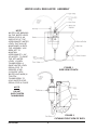
Installation/Service Manual Circulating Water Baths Models 260 (2864/2865), 265 (2866/2867), 270 (2868/2869) On High Temp. Thermo Scientific 401 Millcreek Road, Box 649 Marietta, Ohio 45750 USA Phone: 740-373-4763 Toll Free: 800-438-4851 FAX: 740-373-4189 Manual P/N 3177890 Rev. L Dated 01JAN10 Off NOTE: THE 230V UNITS DESCRIBED IN THIS MANUAL WERE DESIGNED SPECIFICALLY FOR THE EUROPEAN MARKET AND ARE SUPPLIED WITH A EUROPEAN STYLE POWER CORD. FOR DOMESTIC USE, A U.S. STYLE POWER CORD (P/N: 3176836) MUST BE ORDERED SEPARATELY. NOTICE THE MATERIAL IN THIS MANUAL IS FOR INFORMATION PURPOSES ONLY. THE CONTENTS AND THE PRODUCT IT DESCRIBES ARE SUBJECT TO CHANGE WITHOUT NOTICE. THERMO SCIENTIFIC MAKES NO REPRESENTATIONS OR WARRANTIES WITH RESPECT TO THIS MANUAL. IN NO EVENT SHALL THERMO BE LIABLE FOR ANY DAMAGES, DIRECT OR INCIDENTAL, ARISING OUT OF OR RELATED TO THE USE OF THIS MANUAL. For repair information or replacement parts assistance from the manufacturer, call Technical Services using our toll free telephone number. 800-438-4851 (FAX) 740-373-4189 REVISION STATUS INDEX DATE AMENDED PAGES NOTES A 6/99 B 5/00 16 Update pump assembly kit numbers (new pumps) C NOV01 6 D APR02 5,8,27 Add caution "acidic & caustic substance ....." Add inlet screen info, correct wire color E APR05 36100125 (34002503) F APR06 ECR 23196/BA-612 modified drain assembly (connection to H20 regulator) G MAY06 ECR 23443 consolidated with 230V 3177687 removed CE symbol and declaration H SEPT08 ECR 24808 Revised water specifications I MAR09 ECR 25448/BA-670 Added UL required information J MAY09 ECR25227/BA-667 page 22 - half coupling K JUN09 ECR25432/BA-676 CPU board illustrations (pgs. 13 & 14) L JAN10 ECR25572/BA-673 thermal cutout sw in heater circuit, rev schematics Initial release new manual #, manufacture location Contents INTRODUCTION .................................................................................................................. 1 UNPACKING AND DAMAGE .............................................................................................. 1 GENERAL INFORMATION .................................................................................................. 2 PERFORMANCE ................................................................................................................. 2 INSTALLATION ................................................................................................................... 2 WATER LEVEL REGULATOR ........................................................................................... 3 EXPLANATION OF CONTROLS ........................................................................................ 6 OPERATION ........................................................................................................................ 7 MAINTENANCE ................................................................................................................... 8 TROUBLESHOOTING ........................................................................................................ 8 PARTS REPLACEMENT .................................................................................................. 13 TEMPERATURE CALIBRATION ...................................................................................... 16 REPLACEMENT PARTS LIST ......................................................................................... 17 ASSEMBLY & SCHEMATIC DWGS ................................................................................. 19 WARRANTY ...................................................................................................................... 28 INTRODUCTION UNPACKING AND DAMAGE Your satisfaction and safety are important to Thermo and a complete understanding of this unit is necessary to attain these objectives. Save all packing material until unit is put into service. This merchandise was carefully packed and thoroughly inspected before leaving our factory. As the user of this apparatus, you have the responsibility to understand the proper function and operational characteristics of your bath. This instruction manual should be thoroughly read and all operators given adequate training before attempting to place this unit in service. Awareness of the stated cautions and warnings, and compliance with recommended operating parameters — together with maintenance requirements — are important for safe and satisfactory operation. The unit should be used for its intended application; alterations or modifications will VOID THE WARRANTY. Responsibility for safe delivery was assumed by the carrier upon acceptance of the shipment; therefore, claims for loss or damage sustained in transit must be made upon the carrier by the recipient as follows: 1. Visible Loss or Damage: Note any external evidence of loss or damage on the freight bill, or express receipt, and have it signed by the carrier's agent. Failure to adequately describe such external evidence of loss or damage may result in the carrier's refusing to honor your damage claim. The form required to file such claim will be supplied by the carrier. 2. Concealed Loss or Damage: Concealed loss or damage means loss or damage which does not become apparent until the merchandise has been unpacked and inspected. Should either occur, make a written request for inspection by carrier's agent within fifteen (15) days of the delivery date; then file a claim with the carrier since the damage is the carrier's responsibility. WARNING AS A ROUTINE LABORATORY PRECAUTION, ALWAYS WEAR SAFETY GLASSES WHEN WORKING WITH THIS APPARATUS. This product is not intended, nor can it be used, as a sterile or patient connected device. In addition, this apparatus is not designed for use in Class I, II or III locations as defined by the National Electrical Code. CAUTION WHEN UNPACKING THIS PRODUCT, TWO PERSONS ARE REQUIRED TO LIFT THE WATER BATH AND PLACE IT ON A BENCH. THE BENCH TOP MUST BE RIGID AND STRONG ENOUGH TO COMFORTABLY SUPPORT THE WEIGHT OF THE UNIT WHEN FILLED WITH WATER. P/N: 3177890 1 If you follow the above instructions carefully, we will guarantee our full support of your claim to be compensated for loss or concealed damage. DO NOT — FOR ANY REASON — RETURN THIS UNIT WITHOUT FIRST OBTAINING AUTHORIZATION. In any correspondence to Thermo, please supply the nameplate data, including catalog number and serial number. GENERAL INFORMATION PERFORMANCE DATA Precision Circulating Baths are widely used in research and quality control. Their superb temperature uniformity and stability makes them especially desirable for legal or reference tests. The following table identifies the specifications for the Circulating Baths. With Cover The microprocessor control panel houses all functions necessary to operate the bath. The 5 push-button switches and single digital display window allow the operator to adjust bath temperature and temperature calibration via a single set of controls. 3166680 3166682 3166684 3166685 3166681 3166683 2864/ 2865 2866/ 2867 2868/ 2869 P/N: 3177890 Amps 120 50/60 1050 8.8 240 50/60 1050 4.4 120 50/60 1550 12.9 240 50/60 1550 6.5 120 50/60 1550 12.9 240 50/60 1550 6.5 ±0.05°C ±0.05 Sensitivity 37°C ±0.05 ±0.05°C ±0.05 Environmental ConditionsThis instrument is designed to operate safely under the following conditions: • Indoor Use Only • Temperature: 5° to 40° C • Maximum Relative Humidity: 80% to 31°C, decreasing linearly to 50% at 40°C • Maximum Altitude 2000 meters • Mains supply voltage fluctuation ±10%, or per project plan • Installation (Overvoltage) Category II1 • Pollution Degree 22 1 Installation category (overvoltage category) defines the level of transient overvoltage which the instrument is designed to withstand safely. It depends on the nature of the electricity supply and its overvoltage protection means. For example, in CAT II which is the category used for instruments in installations supplied from a supply comparable to public mains such as hospital and research laboratories and most industrial laboratories, the expected transient overvoltage is 2500V for a 230V supply and 1500V for a 120V supply. 2 Pollution Degree describes the amount of conductive pollution present in the operating environment. Pollution Degree 2 assumes that normally only non-conductive pollution such as dust occurs with the exception of occasional conductivity caused by condensation. Listing of Models Included In This Manual Watts ±0.05 Location - The most uniform operating conditions will be obtained by placing the bath on a level surface in an area remote from drafts, ventilating outlets, radiators, and other rapidly changing ambient conditions. The 240-volt units are identical in appearance to the 115-volt units. Hertz Uniformity 37°C WARNING The interior of the bath is constructed of stainless steel and is designed for operation with distilled water or water solutions, such as water /ethylene glycol with corrosion inhabitants added. The body is made from galvanized steel and is painted for added protection. A drain is located at the far left hand end of the bath. A stainless steel gable cover is also provided with the bath. Volts Model 2868/2869 INSTALLATION SHOULD BE COMPLETED BY QUALIFIED PERSONNEL ONLY. A high limit thermostat is provided and can be set to prevent heater runaway in the event of temperature control failure. Model Model 2866/2867 INSTALLATION The proportional integral temperature control coupled with agitation supplied by a centrifugal pump located in the control housing allows precise temperature control. Use of the gable cover provided is required to maintain optimal temperature sensitivity. Category Number Model 2864/2865 2 Maximum performance is assured across the following temperature range: • 15ºC to 45ºC Electrical Connections - IMPORTANT For personal safety, this apparatus must be properly grounded. 1. 2. The power cord provided on this unit is equipped with a three-prong (grounding) plug which mates with standard three-prong grounding wall receptacle to minimize the possibility of electric shock hazard from this apparatus. If in doubt, the user should have the wall receptacle and circuit checked by a qualified electrician to make sure the receptacle can provide adequate current and is properly grounded. Where a standard two-prong wall receptacle is encountered, it is the personal responsibility and obligation of the user to have it replaced with a properly grounded three-prong wall receptacle. Do not, under any circumstances, cut or remove the third (ground) prong from the power cord. Do not use a two-prong adapter plug. Determine the total amount of current being used by other apparatus connected to the circuit that will be used for this apparatus. It is critical that the added current demand (see nameplate) of this and other equipment used on the same circuit does not exceed the rating of the fuse or circuit breaker. Electrolysis can damage stainless steel. This can occur if an object is allowed to rest directly on the surface, trapping moisture that becomes oxygen starved but is surrounded by water containing oxygen. The resulting electrolytic action will pit or erode the stainless steel. WATER LEVEL REGULATOR (OPTIONAL) INSTALLATION INSTRUCTIONS - Use the following steps along with Figure 1 and 2 shown on the following page. 1. Turn off unit, disconnect power & drain water from the bath. 2. Unscrew drain plug from side of bath body. 3. Replace with elbow connector and reducing bushing (shipped loose). Note the reducing bushing is used on units built after February 2006. NOTE TO INSURE GOOD SEAL, WRAP THREADS WITH TEFLON TAPE OR EQUIVALENT SEALER. 4. Tighten elbow connector so open end (tube fitting) faces straight down. 5. Place Water Level Regulator Bracket Assembly on the lip of the bath pan (drain side of the bath towards the rear of the unit). The small flange with gasketing near the top of the bracket should rest against the inside of the bath pan. The other 2 flanges with gasketing should rest against the outside of the bath body. 6. Insert the plastic tubing (coming from the bottom of the water level regulator) into the elbow connector (at the drain) & tighten the elbow connector fitting firmly to insure a good seal. 7. Uncoil Tygon tubing & press onto 1/4" Hose Barb Fitting (located at the top of water level regulator). Hose clamps are provided to ensure a good seal. 8. Hook-up other end of the tygon tubing to water supply & turn on water. (Water pressure should fall within the following range: MIN is approx. 15 PSI, MAX is approx 75 PSI) CAUTION The power supply must be the same voltage as specified on the nameplate. The power cord is the MAINS disconnect. Be sure that it is easily reached to disconnect the unit from the power source. To avoid build-up of mineral deposits and prevent corrosion, use only distilled water in the bath. Using chlorinated tap water or additives that contain chlorine will void the manufacturer’s warranty. Similarly, high purity (deionized) water that does not fall into the 50K to 1M ohm range and 7 to 9 pH range will also void the warranty. Contact Technical Services with any questions. P/N: 3177890 3 WATER LEVEL REGULATOR ASSEMBLY NOTE WATER LINE MARKING ON THE WATER LEVEL REGULATOR IS AN INDICATOR OF THE APPROXIMATE WATER LEVEL THAT WILL BE MAINTAINED IN BATH. THE ASSEMBLY HAS BEEN SET TO MAINTAIN APPROXIMATE 1-3/4" OF WATER. TO RAISE THE SET WATER LEVEL, LOOSEN THUMBSCREW & RAISE WATER LEVEL REGULATOR TO DESIRED LEVEL (COINCIDE WITH WATER LINE MARK) & TIGHTEN THUMBSCREW TO HOLD WATER LEVEL REGULATOR IN PLACE. FIGURE 1 SIDE VIEW OF BATH NOTE: DO NOT OVER-TIGHTEN THUMBSCREW FIGURE 2 CUTAWAY FRONT VIEW OF BATH P/N: 3177890 4 INLET SCREEN ASSEMBLY (OPTIONAL) An optional inlet screen assembly is packaged with each unit. If used, this screen will filter foreign materials (i.e. pieces of paper) from being sucked through the pump. To install the screen assembly, refer to the diagram below. NOTE: IF USED, THE SCREEN ASSEMBLY MUST BE INSPECTED DAILY. REMOVE ANY DEBRIS FOUND ON THE SCREEN. WATERBATH PAN SILICON HOSE INLET NUT TUBE ADAPTER SCREEN ASSEMBLY (FINGER TIGHTEN ONLY) NOTE: INLET IS THE LOWER OF THE 2 PORTS DIRECTION OF WATER FLOW P/N: 3177890 5 EXPLANATION OF CONTROLS Power Switch - The power switch is located on the lower right hand side of the bath, it provides power for the entire unit. Hi-Limit Thermostat - is located immediately to the left of the power switch on the lower right hand corner of the bath. The high limit is an adjustable control used to prevent thermal runaway in the event that the primary control fails. After you have stabilized the bath temperature, use a standard screwdriver to adjust the potentiometer. When delivered, the Hi-Limit is turned fully clockwise (highest setting). In this position the Hi-limit light will be OFF. Turn the potentiometer counterclockwise until the Hi-Limit light is ON, and thenadjust clockwise 1/8 of FIGURE a turn. Verify that the Hi-Limit light 1 is OFF. Now if your bath temperature rises above the desired setting 2 the Hi-Limit protection will be activated. Control Panel The Control panel is located on top of the bath and provides primary temperature control. The Control Panel contains the following features (See Figure A) 1. LED Display 4-digit display used to show both actual and set point values for the temperature. Also shows configuration parameters when in configuration mode. 2. Heater on Lamp - the Heater on Lamp is lighted when power is applied to the heating element. 3. Indicator Lamps - These lamps indicate which parameter (Actual Temp or Setpoint Temp) is displayed in LED window. 4. Set Point Key - The Set Point Key is used to toggle the display between actual bath temperature and the setpoint value. 5. Temperature Selection Keys The Temperature Selection Keys are used to select the desired temperature setpoint value and are only active after theSet Point Key has been pressed. A 3 Bath Te mp ., °C Actual Se t Point He ate r On 4 Se t Point 6. Enter Key The Enter Key is used to store a new set point value. ENTER Offse t 5 To ad just te mp e ra ture : Pre ss Set Point. Pre ss S or T until value is d isp laye d . Pre ss ENTER to store the ne w value. 6 P/N: 3177890 7 6 7. Offset Key The Offset Key is used to adjust the actual temperature value to match a calibrated reference thermometer. 4. OPERATION CAUTION: EXERCISE CARE WHEN USING ACIDIC OR CAUSTIC SOLUTIONS AS THEY WILL ATTACK THE GALVANIZED STEEL BATH BODY IF SPILLED INTO THE BATH. IF SPILLS DO OCCUR, THE BATH LIQUID SHOULD BE IMMEDIATELY DRAINED AND THE UNIT THOROUGHLY FLUSHED. SPILLS AND CONDENSATION SHOULD BE CLEANED/ REMOVED FROM ALL METAL SURFACES AFTER EACH USE. To adjust temperature offset: a. Temperature offset should be used to match a stable bath's actual temperature display to a calibrated thermometer. b. Press ENTER until actual temperature is displayed. c. While pressing OFFSET, press UP or DOWN until display shows the DIFFERENCE between displayed temperature and reference thermometer. Continue holding offset and press ENTER to set new value. When filling the bath with water, allowance must be made for the displacement of water upon immersion of samples. d. Display should now match your calibrated thermometer. CAUTION e. If ENTER is not pressed, new value will not be set and display will return to previous actual temperature. WATER LEVEL REQUIREMENTS MINIMUM LEVEL - WATER LEVEL SHOULD BE 1½ INCHES ABOVE THE PUMP OUTLET. THIS WILL KEEP THE PUMP FROM RUNNING DRY AND FAILING TO OPERATE. MAXIMUM LEVEL - WATER LEVEL SHOULD NOT BE HIGHER THAN 1 INCH FROM THE TOP OF THE BATH PAN. To conserve energy, reduce evaporation and increase temperature control accuracy, use the gable cover provided. Do not use aluminum foil as a cover, as it may cause corrosion due to an electrochemical reaction. 1. Add distilled water to bath. Use water levels as instructed above. 2. Power up: Depress the power switch located at the lower right hand corner of the bath. The unit is fully operational upon application of power and the display will read actual bath temperature 3. To set temperature control point: a. Press SETPOINT. The display will now show the current temperature setpoint. b. Press UP or DOWN until the desired temperature setpoint is displayed. c. Press ENTER to store the new value. Example: Setpoint is 37° and actual bath temperature display is stable at 37°. Calibrated reference thermometer reads 37.2°. Press OFFSET and UP until display reads .2. Press ENTER while still holding OFFSET key. Release keys. Actual bath temperature will read 37.2°. Readjust setpoint to 37° by repeating step 3. NOTE AS WATER BATHS ARE OPERATED, ESPECIALLY AT ELEVATED TEMPERATURES, CONDENSATION WILL FORM ON THE UNDERSIDE OF THE GABLE COVER. THE AMOUNT OF CONDENSATION CAN BE CONSIDERABLE. CARE SHOULD BE EXCERCISED WHEN REMOVING THE COVER SO THAT WATER WILL FALL BACK INTO THE BATH CHAMBER, AND NOT ON THE BATH SURFACE. THE COVER SHOULD BE PLACED UPSIDE DOWN WHEN REMOVED TO MAINTAIN A DRY WORK AREA. CAUTION WHEN OPERATING AT TEMPERATURES GREATER THAN 60ºC, DO NOT TOUCH THE METAL SURFACE OF THE GABLE COVER. LIFT THE GABLE COVER BY THE KNOB ONLY. WARNING d. Display will return to actual temperature. e. If ENTER is not pressed, new value will not be set and display will return to actual temperature. P/N: 3177890 f. 7 EXPLOSION, IMPLOSION OR THE RELEASE OF TOXIC OR FLAMMABLE GASES ARISING FROM THE MATERIAL BEING HEATED IS THE SOLE RESPONSIBILITY OF THE USER. . CAUTION MAINTENANCE Cleaning: Stainless steel will resist corrosion; however, it is not impervious to it. Proper maintenance of the stainless steel bath chamber will help ensure many years of service. CAUTION AVOID SPILLING HARSH CHEMICALS ONTO THE BATH, AS CORROSION OF THE STAINLESS STEEL MAY RESULT. NEVER USE THE FOLLOWING CHEMICALS: -Aqua Regia -Ferric Chloride -Iodine -Sodium Azide -Sulfuric Acid Removing Discoloration: Should the stainless steel ever become discolored by iron rust, use the following procedure to remove all traces of the rust and restore the stainless steel. WARNING THE USER HAS THE RESPONSIBILITY FOR PERFORMING APPROPRIATE DECONTAMINATION IF HAZARDOUS MATERIAL IS SPILT ON OR INSIDE THE BATH. OBSERVE THE FOLLOWING SAFETY PRECAUTIONS! USE HEAVY GLOVES OR OTHER ADEQUATE HAND PROTECTION. WEAR GOGGLES OR OTHER ADEQUATE EYE PROTECTION. ONLY WORK IN AREAS WITH ADEQUATE VENTILATION. It should be cleaned regularly with mild soapy water and rinsed with distilled water. Should algae or other undesirable microorganisms form on the top of the bath media, add a little formaldehyde or quaternary ammonium germicide, available from Thermo (P/N 3166250). Prepare a solution of 20% nitric and 1.5% hydrochloric acid (if preferred, a 2% to 5% solution of warm oxalic acid may be used). Swab solution over surface, allowing it to remain until all rust is loosened. This will usually take 1 to 2 minutes. CAUTION As soon as rust is loosened, immediately flush with clean water until all acid is removed. IMPORTANT DO NOT USE OTHER CLEANING OR DECONTAMINATION METHODS WITHOUT FIRST CONTACTING TECHNICAL SERVICES TO CHECK THAT THE PROPOSED METHOD WILL NOT DAMAGE THE EQUIPMENT. IMPORTANT IF IT IS NECESSARY TO USE THE FOLLOWING CHEMICALS, LIMIT THE TIME TO A MAXIMUM OF FOUR HOURS. CLEAN SURFACES IMMEDIATELY AFTER USE. -Aluminum Chloride -Bichloride of Mercury -Carbolic Acid -Citric Acid (boiling) -Ferrous Chloride -LysolMercuric Chloride -Potassium Permanganate -Potassium Thiocyanate -Sodium Hypochlorite P/N: 3177890 -Barium Chloride -Calcium Chloride -Chlorinated Lime -Dakin's Solution -Mercury Salts -Phenol -Tartaric Acid -Stanous Chloride Screen assembly option: If this option is installed, inspect daily and remove any debris from the screen. Periodic Safety Check Test the operation of the Hi-Limit thermostat, as described on page 6, every three months. TROUBLESHOOTING WARNING SERVICE SHOULD BE PERFORMED BY A QUALIFIED TECHNICIAN. BEFORE REPLACING ANY ELECTRICAL OR MECHANICAL COMPONENTS, UNPLUG THE LINE CORD. IF ELECTRICAL POWER IS REQUIRED FOR SERVICE, USE EXTREME CARE. Refer to Problems and Solutions for troubleshooting information on the baths. This guide provides the basic information required to repair the bath. 8 the power supply board at J102 and then repeat steps 3 thru 6. Do not connect the connector to the CPU board at this time . If the above voltages are not measured again, the display board has a bad component which is loading down the voltages. If the voltages are still present, continue on to step 9. The following is a list of the tools and instruments required to perform the procedures outlined in the Troubleshooting Procedures table. Tools Needed: • • • • • • Phillips or Flat Blade Screwdriver 7/16" Socket or adjustable wrench Ohmmeter DC Voltmeter AC Voltmeter 5VDC Power Supply 9. When changing circuit boards, please use CAUTION when re-installing the flat cable connectors that come from the display board. Make sure the pins are NOT bent or broken. Boards that are otherwise fine will not operate correctly if these pins have been abused because they will not receive the necessary signals from other boards. Before attempting any troubleshooting for a particular problem, it is good practice to verify power supply voltages of the POWER SUPPLY board #3176677. Read these steps before performing them to get acquainted with the procedure. Refer to Figure 1 on page 13. 1. Be sure that the main power source is OFF or disconnected. 2. Connect J101 and J105 to the POWER SUPPLY BOARD. DO NOT connect J102 that comes from the CPU and the DISPLAY at this time. 3. Connect the negative lead of the voltmeter to TP2 - COM. Select a VDC of 20. Connect the positive lead to TP1 - UNREG. 4. Turn ON the main power. 5. The voltmeter should be reading approximately 14 volts DC ±2. 6. Connect the positive lead to TP3 ±5V. The voltmeter should be reading +5 volts DC ±0.5. 7. 8. Turn OFF main power. Connect the display board ribbon connector to P/N: 3177890 9 Connect the display board ribbon connector to the CPU board J310 and repeat steps 3 thru 6. If the above voltages are not measured again, the CPU board has a bad component which is loading down the voltages. This board will have to be replaced. GENERAL INFORMATION: The POWER SUPPLY PCB ASSEMBLY #3176677 has the triac (solid state AC voltage switch) on it which supplies the power to the heater. This triac is "told" to operate, when need be, by the microprocessor. There is another device known as an opto-coupler which serves as the high/low voltage isolator between the triac and the microprocessor. When the bath starts experiencing temperature problem and/or variations, due to known controller malfunctioning, these two components become prime suspects. The reason being they are under higher operating stress than other components. If the bath starts experiencing temperature problems such as no heat, or "creeping" upward heat, then follow the troubleshooting instructions below. These instructions require the use of a voltmeter being able to measure DC and AC voltages (preferably digital) and an ohmmeter. c. Measure the output of the temperature sensor at J302 pins 2 & 3. Pin 3 being the reference or ground. The output relationship of voltage to °C is listed in the table below. Compare the measured voltage to the temperatures listed to determine if the probe is working. WARNING THE FOLLOWING TROUBLESHOOTING INSTRUCTIONS REQUIRE THAT POWER BE ON. ONLY QUALIFIED SERVICE PERSONNEL SHOULD PERFORM THESE PROCEDURES. Open the control cover and familiarize yourself with the POWER SUPPLY assembly #3176677. Locate the triac (Q2), the opto-isolater (U1), the resistor (R4), and the test point #2 (TP2-COM). The first measurements will be DC voltage measurements. A DC scale of at least 10 volts should be selected. PROBLEMS & SOLUTIONS *********** Problem A : No Heat ************* 1. Verify that the setpoint temperature is greater than the actual water temperature. 2. Verify that the HIGH TEMP light is "OFF". If the light is "ON", turn the HIGH LIMIT CONTROL fully clockwise. 3. 4. 5. Temp °C Volt Temp °C Volt 10 0.500V 60 1.400V 20 0.680V 70 1.580V 30 0.860V 80 1.760V 40 1.040V 90 1.940V 50 1.220V 99 2.218V The bath is not heating when it should be requesting heat. Voltage measurements are made on the POWER SUPPLY BOARD #3176677. Refer to Figure 1 on page 13. a. Select a setpoint temperature at least 10°above what the actual temperature is. The bath should be requesting heat as indicated by the heater "ON" indicator lamp on the front panel. It should be on continuously, not flashing. Check temperature probe voltage reference. These measurements are on the CPU board #3176678. Refer to Figure 2 on page 14. a. Place the negative lead of a DC voltmeter on TP1-COM test point. Measure the voltage at U7-pin 2. It should be approximately 14 volts DC. Now measure the voltage at U7-Pin 6. It should be approximately 5 volts DC. If the 14 volts is present but not the 5 volts, the CPU board must be replaced. b. Measure the voltage at U1-PIN 2 with respect to TP2-COM. It should be no greater than 4 VDC. Check temperature probe. d. If the last two steps are not as stated, then most likely the CPU board is bad and it will have to be replaced. c. Measure the DC voltage across R4. Since the bath is requesting heat, there should be current flowing through this resistor making the voltage drop equal to 3VDC, ±0.5. a. Measure the bath water temperature and make note of it. Make sure it will not change drastically during this check. e. Switch the voltmeter to an AC volts scale capable of reading 120 volts. b. With a DC voltmeter, measure the supply of the temperature sensor at J302 pins 1 & 3. It should be approximately 5 volts. If it is, then continue on to step C. If not, see Step 3a. P/N: 3177890 f. Measure the voltage between U1-PIN 4 and U1-PIN 6. It should be less than 1 VAC. g. If it is not, then most likely the opto-coupler U1 is bad and the POWER SUPPLY board will have to be replaced. If it is, continue on. 10 h. Measure the voltage directly across the heater. It should be line voltage 110VAC to 120 VAC. i. 6. c. Measure the DC voltage across R4. The voltage should be approximately zero volts. d. If the last two steps are NOT as stated, then most likely the CPU board is bad and it will have to be replaced, otherwise continue on. If it is not, then most likely the triac Q2 is bad, and the POWER SUPPLY board will have to be replaced. Check heater. e. Switch the voltmeter to an AC volts scale capable of reading 120 volts. a. Disconnect the bath from its electrical supply. f. b. Isolate the heater from any circuitry by disconnecting one of the heater leads. g. If it is not, most likely the opto-coupler U1 is bad and the POWER SUPPLY board will have to be replaced. If it is, continue on. c. Using an ohmmeter, check the heater resistance. Appropriate heater resistance values are listed below: If the resistance reads 0 or infinity, then replace the heater. 115 VOLT h. Measure the voltage directly across the heater. It should be approximately 0 VAC. 230 VOLT i. Model 2864/2865 15 OHMS 60 OHMS Model 2866/2867 10 OHMS 40 OHMS Model 2868/2869 10 OHMS 40 OHMS 2. d. Check the resistance between the heater leads and ground (green wire). If the resistance reads 0 ohms, replace the heater. ********* Problem B: Constant Heat ********* 1. a. Select a setpoint temperature at least 10° below the actual temperature. The bath should not be requesting heat as indicated by the HEATER ON indicator lamp on the front panel. It should NOT be on continuously or even flashing. b. Measure the voltage at U1-PIN 2 with respect to TP2-COM. It should be no less than 4 VDC. Refer to Figure 1 on page 13. 11 If it is not, then most likely the triac Q2 is bad,and the POWER SUPPLY board will have to be replaced. Check Temperature Probe. Problem A, Step 4. *** Problem C: Unstable Temperature *** Control or Display 1. Use gable cover provided to improve temperature control. 2. If control is stable but not at desired temperature, then check temperature calibration. Re-adjust if necessary. 3. Check Temperature Probe, Problem A, Step 4. Bath is heating when it is not requesting heat. P/N: 3177890 Measure the voltage between U1-PIN 4 and U1-PIN 6. It should be line voltage 110 VAC to 120 VAC. ** Problem D: Display Reads NNNN or UUUU ** The control boards have the ability to detect an OPEN or SHORTED temperature sensor. These two conditions are shown on the display as follows: DISPLAY CONDITION *** Problem F: Pump Does Not Circulate *** Water 1. Verify that the water level is above both the pump inlet and outlet. 2. If the pump is not running, verify that power is applied to the bath. If power is present, check wiring of pump to power switch. If wiring is correct, replace the pump. 3. If pump is running but water is not circulating, open the control panel and gently squeeze the long piece of rubber tubing a few times to help remove any air trapped within the pumping system. 4. If water is still not circulating, check for foreign matter in the pump inlet fitting. SHORT CIRCUIT OPEN CIRCUIT Before coming to the conclusion that the probe is bad when one of these displays appear, check the connection of the probe to the circuit board for polarity and alignment. * Problem E: Display Reads all Eights (8888) * 1. The most common problem cause of this problem is the failure of the driver integrated circuit on the DISPLAY/KEYBOARD board (#3176679). Replace it. P/N: 3177890 12 P/N: 3177890 13 +5Vdc ±0.5Vdc Power Supply Ground TP2 +14Vdc ±2Vdc U1, pin 4 R4 (Unless otherwise specified, measure all D.C. voltage with reference to TP2) Figure 1 - POWER SUPPLY PCBA - 3176677 U1, pin 2, 4Vdc when HEAT is ON continuously Heater Power Triac P/N: 3177890 14 U7, pin 2 §14Vdc TP3 = 5Vdc, ±0.5Vdc J302, pin 1 Figure 2 - CPU PCBA – 3176678 (Unless otherwise specified, measure all D.C. voltage with reference to TP2) Power Supply Ground TP2 = 5Vdc, ±0.5Vdc PARTS REPLACEMENT WARNING Before removing any parts for replacement, verify part in question by following the instructions listed in the troubleshooting guide. Refer to Parts Replacement Table below for appropriate replacement procedures. Failure to follow parts replacement procedures may cause damage to the bath. BEFORE REPLACING ANY PART, TURN POWER SWITCH TO OFF, THEN UNPLUG THE UNIT FROM ITS POWER SOURCE. SERVICE SHOULD BE PERFORMED BY A QUALIFIED TECHNICIAN. CAUTION WHEN REPLACING TEMPERATURE SENSOR, HEATER OR CIRCULATING PUMP, MAKE SURE ALL SEALS ARE WATERTIGHT BEFORE APPLYING ELECTRICAL POWER. PARTS REPLACEMENT NOTE: For easiest access to the control housing, place bath on the edge of a bench or table. Remove four screws on upper side of control housing and carefully lower hinged control panel to the vertical position. Circulating Pump 1. Drain water from bath. Replacement 2. Remove the two pump leads attached to power switch and green wire from pump to ground lug. 3. Loosen the two visible hose clamps with a screwdriver and remove tubing from pump. 4. Disconnect pump from pump bracket by removing two screws and remove pump from bath. 5. Reverse above procedure to install new circulating pump. Replace Temperature Sensor 1. Drain water from bath. 2. Remove diffuser pan from bath. 3. Remove connector J302 from CPU board. 4. Remove temperature sensor fitting from inside bath pan. - Hold small nut on fitting firmly with a wrench. - Remove large fitting piece with another wrench. 5. Remove rubber grommet from temperature sensor. 6. Carefully slide sensor through the control housing and remove. 7. Reverse above procedure to install new temperature sensor. 8. Recalibrate new temperature sensor. See Temperature Calibration on page 15. P/N: 3177890 15 PARTS REPLACEMENT (CONT'D) Replace Heater 1. From inside control housing, remove 2 nuts and disconnect wires from heater leads. 2. Remove two hex nuts from heater ends using a 13/16" socket and remove heater. 3. Reverse above procedure to install new heater. Replace "HI LIMIT" Thermostat 1. Remove four leads from thermostat terminals. 2. Remove two screws from thermostat bracket and remove bracket. 3. Carefully tilt bath on its side. 4. Remove eight screws from bottom plate and remove plate. 5. Remove insulation from bottom of pan and between pan and control panel wall. 6. Loosen two nuts from thermostat bulb bracket. 7. Carefully remove thermostat from control housing by sliding bulb through hole in control panel wall. 8. Reverse above procedure to install new Hi Limit thermostat. Use extreme care when installing new thermostat. A sharp bend in the thermostat capillary will crimp off flow of hydraulic fluid. Replace Power Supply Board 1. Remove connectors J101, J102, J103, and J105 from board. Use extra care when removing J102 so as not to bend connector pins. 2. Remove five nuts from board and then remove it. 3. Reverse above procedure to install new power supply board. Replace CPU or Display/Keyboard Board See note on the following page ** 1. Remove connectors J302 and J303 from CPU board. 2. Remove connector J102 from power supply board. Use extreme care when removing J102 so as not to bend connector pins. 3. Remove four nuts from CPU board and remove CPU board and Keyboard/Display board. 4. Remove J201 from CPU board. Use extreme care when removing J301 so as not to bend connector pins. Remove board. 5. Reverse above procedure to install new board. P/N: 3177890 16 PARTS REPLACEMENT (CONT'D) Replace CPU or Display/Keyboard Board See note below ** 6. The software must be configured to match the Bath model. To enter configuration mode, press the upper left pushbutton switch while applying power. The upper left switch is labeled "Set Point." This switch is used to enter configuration codes and steps through the different levels of configurations. When a triangle is shown in the chart, the pushbutton is to be depressed once for each symbol. Immediately following power up with the switch depressed, the readout will display a 3-digit number. This is the software revision. The readout will then begin to do a self-test of digits. Press the "Set Point" button once. The readout will display 0000. Follow the listing below to complete the configuration. A. Enter 37 using up/down arrows. Press "Set Point" B. Enter 31 using up/down arrows. Press "Set Point" C. Enter 2.0 using up/down arrows. Press "Set Point" D. Enter 500 using up/down arrows. Press "Set Point" E. Enter 1 using up/down arrows. Press "Set Point" F. Display Not Used. Press "Set Point" G. Display Not Used. Press "Set Point" H. LOW TEMP CALIBRATION* LITTLE c. Factory Setting. Press "Set Point" I. HI TEMP CALIBRATION BIG C. Factory Setting. Press "Set Point" Configuration is now complete * Calibration of the low and high end of the sensor input is done at the factory. Field calibration of the sensor may be performed using the following technique: Enter the configuration routine and press the top left switch until a little "c" (Item H) is displayed. Add water that is around 10°C to the bath completely covering the sensor. Insert a calibrated thermometer. After the thermometer stabilizes, match the display setting to the thermometer reading by pressing the "UP" or "DOWN" push button switch. Press the top left switch. The readout will now display a big "C" (Item I). Remove water from the bath and add hot water of about 70 - 80°C. After the unit stabilizes, match readout display to temperature on thermometer and press the top left switch. Calibration is now complete. **Note: When replacing CPU printed circuit board reprogramming may be necessary. Follow thoroughly instructions provided with the replacement circuit board. P/N: 3177890 17 TEMPERATURE CALIBRATION 7. The following instructions provide a step-by-step procedure for temperature calibration. Do not deviate from the procedure or the calibration of your bath may be inaccurate. The display will now show cXX.X (XX.X is the actual bath temperature) - this is Low Temperature Calibration. 8. Place the temperature probe and a calibrated reference thermometer into an ice bath. Press UP or DOWN until the display value matches the reference thermometer. Press SETPOINT to store the new low temperature calibration value. 9. The display will now show CXX.X - this is High Temperature Calibration. (XX.X is the actual bath temperature). CAUTION THIS PROCEDURE SHOULD ONLY BE PERFORMED AFTER INSTALLING A NEW TEMPERATURE PROBE INTO THE BATH. 1. Connect the temperature probe connector to J302 on CPU board. 2. Turn Power switch to the OFF position. 3. Press and hold the SETPOINT key while turning Power ON. 4. The unit will now cycle through an LED display test. Press SETPOINT to end test. 5. The display will now read 0000. Press UP until display reads 0012. Press SETPOINT. NOTE: IF A VALUE OTHER THAN 0012 IS DISPLAYED AND SETPOINT IS PRESSED, THE UNIT WILL RETURN TO NORMAL OPERATING MODE AND DISPLAY WILL SHOW ACTUAL BATH TEMPERATURE. 6. 10. Place the temperature probe and a calibrated reference thermometer into a steaming water bath. Press UP or DOWN until the display value matches the reference thermometer. Press SETPOINT to store the new high temperature calibration value. NOTE PRESSING OFFSET AT ANY TIME DURING THE CALIBRATION PROCESS WILL RETURN UNIT TO NORMAL OPERATION MODE AND DISPLAY WILL SHOW ACTUAL BATH TEMPERATURE. The unit is now in Calibration mode. Raw count value appears. Hit setpoint. P/N: 3177890 18 REPLACEMENT PARTS LIST Model #2864/2865 Model #2866/2867 Model #2868/2869 3166680 3166682 3166684 3166685 3166681 3166683 120V 240V 120V 240V 120V 240V Bath Pan Kit 3167140 3167141 3167142 Diffuser Pan Assy 3164495 3164479 3164500 PCB Kit, PowerSupply 3166924 PCB Assembly, CPU 3167119 PCB Assembly, Display 3176679 Heater Assembly Kit 3167138 3167139 3167136 3167137 3167136 3167137 Voltage Connector 3176698 3176699 3176698 3176699 3176698 3176699 Wire Harness 3176700 Temperature Probe Kit 3167144 'O' Ring Kit, Water Bath 3167129 Tubing Kit 3167145 "Hi-Limit" Thermostat Kit 3167143 ON/OFF Switch 3175318 Hi Limit Light, Amber 3177575 3173907 3177575 3173907 3177575 3173907 Line Cord 3178034 3179481 3178034 3179481 3178034 3179481 Power Cord Receptacle N/A 3179502 N/A 3179502 N/A 3179502 Mains Fuses (2 ea.) N/A 3172449 N/A 3175950 N/A 3175950 Power Supply Brd. Fuse N/A 3175930 N/A 3175930 N/A 3175930 3167333 3167342 3167333 3167342 3167341 3167343 Pump Assembly Kit Drain Kit (includes Nut & O-Ring) 3166191 ACCESSORY PARTS LIST Model #2864/2865 3166680 Cover, Gable 3166682 3166565 Model #2866/2867 3166684 3166685 3166208 Kit, Water Level Regulator 3166223 Sanitizer, Oakite 3166250 Diffuser Shelf, Raised 3165861 P/N: 3177890 19 Model #2868/2869 3166681 3166683 3166230 FRONT VIEW ASSEMBLY AND SCHEMATIC DRAWINGS P/N: 3177890 20 P/N: 3177890 21 115V TOP VIEW (WITH CONTROL COVER OPEN) P/N: 3177890 22 HEATER BRKT. SCREW THERMOMETER HOLDER HEATER WIRE HARNESS SCREW LOCKWASHER WASHER PUMP VOLTAGE CONNECTOR SCREW NUT MAINS FUSES POWER CORD 230V TOP VIEW (WITH CONTROL COVER OPEN) WASHER LOCKWASHER NUT PAN PUMP BRACKET NUT DISPLAY BOARD POWER SUPPLY BOARD CPU BOARD 115V SIDE VIEW (WITH CONTROL COVER REMOVED AND WIRING EXCLUDED) P/N: 3177890 23 THERMOSTAT SCREW CAP SCREW SCREW NUT SCREW SOCKET BRACKET SILICON HOSE PUMP HOSE CLAMP 230V SIDE VIEW (WITH CONTROL COVER REMOVED AND WIRING EXCLUDED) P/N: 3177890 24 O-RING SUPPLIED WITH FITTING TUBE ADAPTER HOSE CLAMP NUT SILICONE HOSE PUMP OUTLET FLEX FITTING TEMP PROBE ASSEMBLY 1/8” HALF COUPLING NUT THERMOSTAT CLIP THERMOSTAT BULB (PART OF THERMOSTAT) TO REMOVE TEMPERATURE PROBE: -HOLD NUT ON INSIDE OF PAN CLOSEST TO PAN WALL FIRMLY WITH WRENCH -REMOVE FLEX FITTING -SLIDE RUBBER GROMMET OVER END OF TEMPERATURE PROBE -SLIDE TEMPERATURE PROBE INTO CONTROL HOUSING FRONT VIEW (CUTAWAY DETAIL OF TEMP PROBE & PUMP OUTLET) P/N: 3177890 25 Pump Inlet Fitting Nut Bath Pan Pump Inlet Heater Heater Lead (part of wire harness) Nut (provided with heater) Bath Body High Temp Cutout O-ring FRONT VIEW (CUTAWAY DETAIL OF PUMP INLET & HEATER) P/N: 3177890 26 TO REMOVE HEATER: -REMOVE HEATER BRACKET(S) FROM INSIDE OF PAN -REMOVE HEATER LEADS FROM END OF HEATER -REMOVE LARGE NUT LOCATED IN AREA BETWEEN PAN AND BODY WALL -LIFT HEATER OUT OF PAN HEATER REMOVAL DETAIL HEX NUT CUTAWAY VIEW OF DRAIN P/N: 3177890 27 CONTROL COVER TO OPTICAL SENSOR TO TEMP PROBE NUT DISPLAY PCB ASSY LOCATED UNDERNEATH CPU PCB ASSY TO POWER SUPPLY BOARD J102 NUT P/N: 3177890 28 P/N: 3177890 29 J201 DISPLAY / KEYBOARD PCB ASSEMBLY 1 2 3 4 5 6 7 8 9 10 11 12 13 14 15 16 GRD Vout 3 RED 1 YELLOW 2 BLACK +5V TEMPERATURE SENSOR ASSEMBLY 1 2 3 4 5 J303 1 2 3 4 5 6 7 8 9 VOLTAGE JUMPER 120V 1 2 3 4 5 6 7 8 9 10 11 12 13 14 15 16 J102 1 2 3 4 5 6 7 8 9 J101 J105 1 2 3 4 J103 1 2 3 4 5 6 7 8 1 2 3 4 5 6 7 8 SCHEMATIC DIAGRAM (120V) 10 11 12 13 14 15 16 1 2 3 4 5 6 7 8 9 J301 CPU PCB ASSEMBLY 1 2 3 J302 RED BLUE BLACK S1 2 5 BLACK PUMP BLACK S2 BLACK (LINE) E2 CONTROL PANEL GROUND E1 CHASSIS GROUND GREEN WHITE (NEUTRAL) W1 WHITE HIGH TEMP CUTOUT HIGH TEMP LIMIT SWITCH OPENS ON TEMP RISE POWER SWITCH 1 4 YELLOW BLACK HIGH TEMP LIMIT LAMP BLACK DS1 HR1 P/N: 3177890 30 J201 DISPLAY / KEYBOARD PCB ASSEMBLY 34373101 1 2 3 4 5 6 7 8 9 10 11 12 13 14 15 16 GRD Vout 3 RED 1 YELLOW 2 BLACK +5V TEMPERATURE SENSOR ASSEMBLY 34541709 1 2 3 4 5 J303 1 2 3 4 5 6 7 8 9 VOLTAGE JUMPER 34376403-230V 1 2 3 4 5 6 7 8 9 10 11 12 13 14 15 16 J102 1 2 3 4 5 6 7 8 9 J101 1 2 3 4 J103 2 3 4 5 6 7 8 1 J105 34372501 1 2 3 4 5 6 7 8 SCHEMATIC DIAGRAM (230V) 10 11 12 13 14 15 16 1 2 3 4 5 6 7 8 9 J301 CPU PCB ASSEMBLY 34373001 1 2 3 J302 RED BLUE BLACK S1 2 5 BLACK PUMP BLACK S2 E2 CONTROL PANEL GROUND W1 FUSES E1 CHASSIS GROUND YLW/GRN BLUE (NEUTRAL) BROWN(LINE) WHITE HIGH TEMP CUTOUT HIGH TEMP LIMIT SWITCH OPENS ON TEMP RISE POWER SWITCH 1 4 YELLOW BLACK HIGH TEMP LIMIT LAMP BLACK DS1 HR1 P/N: 3177890 31 Heater High Temp Cutout Connector To J105 Thermostat Line Cord Power Switch Jumper WIRING CONNECTION DIAGRAM (120v) High Limit Light E2 (Located On Control Panel) Pump P/N: 3177890 32 HEATER HIGH TEMP CUTOUT CONNECTOR TO J105 RED WHITE THERMOSTAT YELLOW BLACK BLACK BLACK BROWN BLUE BLUE GREEN POWER SWITCH TO E1 LINE CORD JUMPER BROWN GREEN TO E1 TO CONTROL PANEL TO PUMP MOTOR BLUE PUMP WIRINNG CONNECTION DIAGRAM (230V) HIGH LIMIT LIGHT E2 (LOCATED ON CONTROL PANEL DETAIL A GROUND CONNECTION-E2 INTERIOR OF BODY (REF) TO PAN LINE CORD TO HEATER P/N: 3177890 33 Rev. 4 4/09 REGISTERED ISO 9001 If equipment service is required, please call your Technical Services Department at 1-800-438-4851 (USA and Canada) or 1-740-373-4763. We're ready to answer your questions on equipment warranty, operation, maintenance, service and special application. Outside the USA, contact your local distributor for warranty information. Your local Thermo Sales Office is ready to help with comprehensive site preparation information before your equipment arrives. Printed instruction manuals carefully detail equipment installation, operation and preventive maintenance. THIS WARRANTY IS EXCLUSIVE AND IN LIEU OF ALL OTHER WARRANTIES, WHETHER WRITTEN, ORAL OR IMPLIED. NO WARRANTIES OF MERCHANTABILITY OR FITNESS FOR A PARTICULAR PURPOSE SHALL APPLY. Thermo shall not be liable for any indirect or consequential damages including, without limitation, damages relating to lost profits or loss of products. Replacement or repair of components parts or equipment under this warranty shall not extend the warranty to either the equipment or to the component part beyond the original warranty period. The Technical Services Department must give prior approval for return of any components or equipment. At Thermo's option, all non-conforming parts must be returned to Thermo Fisher Scientific postage paid and replacement parts are shipped FOB destination. During the first year, component parts proven to be non-conforming in materials or workmanship will be repaired or replaced at Thermo's expense, labor included. Installation and calibration are not covered by this warranty agreement. The Technical Services Department must be contacted for warranty determination and direction prior to performance of any repairs. Expendable items, glass, filters and gaskets are excluded from this warranty. The Warranty Period starts two weeks from the date your equipment is shipped from our facility. This allows for shipping time so the warranty will go into effect at approximately the same time your equipment is delivered. The warranty protection extends to any subsequent owner during the first year warranty period. THERMO FISHER SCIENTIFIC STANDARD PRODUCT WARRANTY P/N: 3177890 34 Rev. 4 2/09 REGISTERED ISO 9001 Contact your local distributor for warranty information. We’re ready to answer your questions on equipment warranty, operation, maintenance, service and special application. Your local Thermo Sales Office is ready to help with comprehensive site preparation information before your equipment arrives. Printed instruction manuals carefully detail equipment installation, operation and preventive maintenance. THIS WARRANTY IS EXCLUSIVE AND IN LIEU OF ALL OTHER WARRANTIES, WHETHER WRITTEN, ORAL OR IMPLIED. NO WARRANTIES OF MERCHANTABILITY OR FITNESS FOR A PARTICULAR PURPOSE SHALL APPLY. Thermo shall not be liable for any indirect or consequential damages including, without limitation, damages relating to lost profits or loss of products. Replacement or repair of components parts or equipment under this warranty shall not extend the warranty to either the equipment or to the component part beyond the original warranty period. The Technical Services Department must give prior approval for return of any components or equipment. At Thermo's option, all non-conforming parts must be returned to Thermo postage paid and replacement parts are shipped FOB destination. During the first year, component parts proven to be non-conforming in materials or workmanship will be repaired or replaced at Thermo's expense, labor excluded. Installation and calibration are not covered by this warranty agreement. The Technical Services Department must be contacted for warranty determination and direction prior to performance of any repairs. Expendable items, glass, filters, reagents, tubing, and gaskets are excluded from this warranty. The Warranty Period starts two months from the date your equipment is shipped from our facility. This allows for shipping time so the warranty will go into effect at approximately the same time your equipment is delivered. The warranty protection extends to any subsequent owner during the first year warranty period. Dealers who stock our equipment are allowed an additional six months for delivery and installation, provided the warranty card is completed and returned to the Technical Services Department. THERMO FISHER SCIENTIFIC INTERNATIONAL DEALER WARRANTY