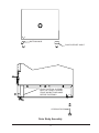
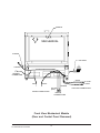
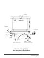
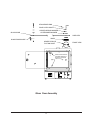
1
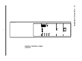
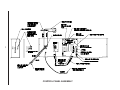
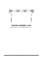
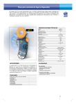
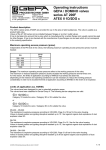
Installation/Service Manual
Thelco Incubator
Models 2DG (3501), 3DG (3503), 5DG (3505),
6DG (3507), 3DM (3509), 5DM (3511), 6DM (3513)
Hig h
Low
On
He ate r On
laboratory
Re cord er
Outp ut
O ff
INCUBATOR
Thermo Electron Corporation
Millcreek Road, Box 649
Marietta, Ohio 45750
USA
Phone: 740-373-4763
Toll Free: 800-848-3080
FAX: 740-373-4189
Manual P/N 3179179
Rev. E Dated 13APR06
ENTER
Tem p .
Hig h
Limit
Mute
NOTE:
THE UNITS DESCRIBED IN THIS MANUAL WERE DESIGNED SPECIFICALLY FOR THE
EUROPEAN MARKET AND ARE SUPPLIED WITH A EUROPEAN STYLE POWER CORD.
FOR DOMESTIC USE, A U.S. STYLE POWER CORD (P/N: 3176836) MUST BE ORDERED
SEPERATELY.
NOTICE
THE MATERIAL IN THIS MANUAL IS FOR INFORMATION PURPOSES ONLY. THE
CONTENTS AND THE PRODUCT IT DESCRIBES ARE SUBJECT TO CHANGE WITHOUT
NOTICE. THERMO ELECTRON CORPORATION MAKES NO REPRESENTATIONS OR
WARRANTIES WITH RESPECT TO THIS MANUAL. IN NO EVENT SHALL THERMO BE
LIABLE FOR ANY DAMAGES, DIRECT OR INCIDENTAL, ARISING OUT OF OR RELATED TO
THE USE OF THIS MANUAL.
For repair information or replacement parts assistance from the manufacturer,
call Customer Service using our toll free telephone number.
800-621-8820
(FAX) 540-869-0130
REVISION STATUS
INDEX
DATE
AMENDED PAGES
NOTES
A
9/99
B
OCT00
inside cover
Add power cord note
C
APR03
4
Update stability specs to match
marketing literature
D
JUL05
51249001
new manual #, manufacture location
E
APR06
ECR 23443
Removed CE symbol and declaration
Initial release for CE mark
Contents
1. INTRODUCTION .............................................................................................................. 1
2. UNPACKING AND DAMAGE .......................................................................................... 1
3. GENERAL INFORMATION ............................................................................................. 2
4. FEATURES ..................................................................................................................... 3
5. SPECIFICATIONS ........................................................................................................... 4
6. INSTALLATION ............................................................................................................... 5
7. EXPLANATION OF CONTROLS ..................................................................................... 5
8. OPERATION .................................................................................................................... 6
9. MAINTENANCE/SERVICE .............................................................................................. 7
10. PARTS REPLACEMENT.............................................................................................. 8
11. REPLACEMENT PARTS LIST/ACCESSORIES ........................................................ 11
12. ELECTRICAL DRAWINGS ......................................................................................... 13
WARRANTY ...................................................................................................................... 24
1. INTRODUCTION
2. UNPACKING AND DAMAGE
1.01 Your satisfaction and safety are important
to Thermo and a complete understanding of this
unit is necessary to attain these objectives.
2.01 Save all packing material if apparatus is
received damaged. This merchandise was carefully
packed and thoroughly inspected before leaving
our factory.
2.02 Responsibility for safe delivery was
assumed by the carrier upon acceptance of the
shipment; therefore, claims for loss or damage
sustained in transit must be made upon the carrier
by the recipient as follows:
1.02 As the ultimate user of this apparatus, you
have the responsibility to understand the proper
function and operational characteristics of your
incubator. This instruction manual should be
thoroughly read and all operators given adequate
training before attempting to place this unit in
service. Awareness of the stated cautions and
warnings, and compliance with recommended
operating parameters — together with maintenance
requirements — are important for safe and
satisfactory operation. The unit should be used for
its intended application; alterations or modifications
will VOID THE WARRANTY.
1.
Visible Loss or Damage: Note any external
evidence of loss or damage on the freight
bill, or express receipt, and have it signed
by the carrier’s agent. Failure to adequately
describe such external evidence of loss or
damage may result in the carrier’s refusing
to honor your damage claim. The form
required to file such claim will be supplied
by the carrier.
2.
Concealed Loss or Damage: Concealed
loss or damage means loss or damage
which does not become apparent until the
merchandise has been unpacked and
inspected. Should either occur, make a
written request for inspection by carrier’s
agent within 15 days of the delivery date;
then file a claim with the carrier since the
damage is the carrier’s responsibility.
WARNING
AS A ROUTINE LABORATORY PRECAUTION,
ALWAYS WEAR SAFETY GLASSES WHEN
WORKING WITH THIS APPARATUS.
1.03 This product is not intended, nor can it be
used, as a sterile or patient connected device. In
addition, this apparatus is not designed for use in
Class I, II or III locations as defined by the National
Electrical Code.
CAUTION
2.03 If you follow the above instructions carefully,
we will guarantee our full support of your claim to
be compensated for loss from concealed damage.
WHEN UNPACKING THIS PRODUCT, USE A
MECHANICL LIFTING DEVICE OR ENOUGH
PEOPLE TO EASILY LIFT THE UNIT AND PLACE
IT IN ITS PROPER LOCATION.
DO NOT — FOR ANY REASON — RETURN THIS
UNIT
WITHOUT
FIRST
OBTAINING
AUTHORIZATION.
THE BENCH TOP OR OTHER MOUNTING
SURFACE, MUST BE RIGIDLY CONSTRUCTED
AND
CAPABLE
OF
COMFORTABLY
SUPPORTING THE WEIGHT OF THE UNIT.
In any correspondence to Thermo, please supply
the nameplate data, including catalog number and
serial number.
WARNING
THIS EQUIPMENT MUST NOT BE MOUNTED
ON A FLAMMABLE SURFACE.
1
3. GENERAL INFORMATION
3.01 This instruction manual encompasses the
following models and their specific electrical
characteristics.
3.02 Models 2DG, 3DG, 5DG, and 6DG employ
gravity convection as a method of heat transfer.
Gravity convection is defined as the natural
tendency for heated air to rise due to it’s change in
density.
Air is drawn into the chamber through openings in
the bottom of the incubator then heated as it
passes over the electric heating coils and up through
the openings in the diffuser panel located on the
bottom of the inner chamber.
3.06 Models 3DM, 5DM, and 6DM incubators
use mechanical convection as a method of heat
transfer. Mechanical convection can be defined as
a positive and planned directional air flow or forced
air circulation within the chamber. Air is drawn into
the chamber through vent tubes located in the
bottom of the incubator and is heated as it passes
over the electric heating coils. The air is blown
through the duct network and forced into the
chamber through the side diffuser walls.
3.07 A limited amount of the heated air is
exhausted out the top of the chamber through the
vent shutter cap and the remaining air recirculates
within the chamber.
3.03 A limited amount of the heated air is
exhausted out of the chamber through the openings
in the vent cap located on the top of the incubator
and the remaining air recirculates within the
chamber.
3.08 Mechanical convection incubators provide
the most efficient means of heat transfer as well as
the most reproducible test conditions for repeat
operations. Mechanical convection allows for rapid
heat up time for high density loads, shortened
recovery periods after door openings and improved
uniformity for extremely heat sensitive materials.
3.04 Gravity convection incubators are ideal
where forced air circulation cannot be tolerated
and for situations demanding gentle curing or long
term sample storage under closely controlled
conditions. Gravity convection incubators are ideal
for heating fluid samples, tissues, and other cells.
3.09 Models 3DM, 5DM, and 6DM provide
mechanical convection of heat controlled by a
microprocessor with digital set point, digital display
and digital safety thermostat.
3.05 Models 2DG, 3DG, 5DG, and 6DG use a
microprocessor control with digital set point, digital
display and digital safety thermostat.
Environmental ConditionsThis instrument is designed to operate safely under
the following conditions:
• Indoor Use Only
• Temperature: 5° to 40° C
• Maximum Relative Humidity: 80% for
•
temperatures to 22°C
Maximum Altitude 2000 meters
Maximum performance is assured across the
following temperature range:
• 15ºC to 45ºC
2
4. FEATURES
®
THELCO HIGH PERFORMANCE INCUBATORS
STAINLESS STEEL CHAMBER
Corrosion/contamination resistant.
Easy to clean and maintain.
ADJUSTABLE EXHAUST PORT
Controls the amount of airflow from the
chamber.
INTERIOR GLASS DOOR
Allows for sample viewing
without disturbing chamber
environment.
FORMED STEEL
EXTERIOR WITH WHITE
POWDER COATING
Durable, easy to clean,
and maintains an
attractive finish.
2" THICK INSULATION
Provides efficient heat
retention and precise
temperature uniformities.
REAR ACCESS PORT
Allows the running of power
cords
to
auxiliary
equipment within the
chamber.
POLYURETHANE
GASKETING Inner glass
door seals tightly on
gasketing to maintain
temperature setpoint.
NON-TIP SHELVING
Each model comes
standard with 2 shelves.
Corrosion resistant nickel
plated, easy to clean, and
simplifies loading and
unloading.
GRABBER DOOR
LATCHES Provide a 4point positive door seal.
RECORDER OUTPUT
Monitors temperature readings for data logging.
DIGITAL DISPLAY LED
Displays temperature to
0.1°C. Microprocessor puts
pushkey temperature setpoint
selection at your fingertips.
STAINLESS STEEL DOOR GUIDE
Supports and aligns door for handsoff closure.
3
5. SPECIFICATIONS
THELCO® High-Performance Incubator Specifications
Model Number
Convection Technique
2DG
3DG
5DG
6DG
3DM
5DM
6DM
Gravity
Gravity
Gravity
Gravity
Mechanical
Mechanical
Mechanical
1.4 cu. ft., 40 liters
2.5 cu. ft., 71.5 liters
4.5 cu. ft., 129 liters
5.5 cu. ft., 157.5 liters
2.5 cu. ft., 71.5 liters
4.5 cu. ft., 129 liters
5.5 cu. ft., 157.7 liters
Temperature Control
Microprocessor
Microprocessor
Microprocessor
Microprocessor
Microprocessor
Microprocessor
Microprocessor
Temperature Display
3 Digit LED
3 Digit LED
3 Digit LED
3 Digit LED
3 Digit LED
3 Digit LED
3 Digit LED
Amb. +5° to 70°C
±0.5°C
±0.1°C
±0.1°C
Amb. +5° to 70°C
±0.5°C
±0.3°C
±0.1°C
Amb. +5° to 70°C
±0.5°C
±0.3°C
±0.1°C
Amb. +5° to 70°C
±0.5°C
±0.3°C
±0.1°C
Amb. +5° to 70°C
±0.25°C
±0.2°C
±0.1°C
Amb. +5° to 70°C
±0.25°C
±0.2°C
±0.1°C
Amb. +5° to 70°C
±0.25°C
±0.2°C
±0.1°C
14.0 x 12.5 x 13.75 in.
356 x 318 x 349 mm
15.5 x 18.5 x 15 in.
390 x 470 x 380 mm
15.5 x 18.5 x 27 in.
390 x 470 x 685 mm
15.5 x 18.5 x 33 in.
390 x 470 x 835 mm
15.5 x 18.5 x 15 in.
390 x 470 x 380 mm
15.5 x 18.5 x 27 in.
390 x 470 x 685 mm
15.5 x 18.5 x 33 in.
390 x 470 x 835 mm
13.5 x 12.5 in.
343 X 318 mm
15.5 x 18 in.
390 X 455 mm
15.5 x 18 in.
390 X 455 mm
15.5 x 18 in.
390 X 455 mm
15.5 x 18 in.
390 X 455 mm
15.5 x 18 in.
390 X 455 mm
15.5 x 18 in.
390 X 455 mm
*Exterior
19.5 x 18 x 28 in.
495 x 457 x 711 mm
21.5 x 24 x 28 in.
550 x 610 x 715 mm
21.5 x 24 x 40 in.
550 x 610 x 1020 mm
21.5 x 24 x 46 in.
550 x 610 x 1170 mm
21.5 x 24 x 28 in.
550 x 610 x 715 mm
21.5 x 24 x 40 in.
550 x 610 x 1020 mm
21.5 x 24 x 46 in.
550 x 610 x 1170 mm
Net Weight
80 lbs., 36 kg
105 lbs., 47 kg
135 lbs., 61.2 kg
150 lbs., 68 kg
115 lbs., 52.2 kg
145 lbs., 65.8 kg
160 lbs., 72.6 kg
**Shelves
Supplied
Maximum
2
6
2
6
2
12
2
15
2
6
2
12
2
15
120 W, 0.5 A
125 W, 0.6 A
150 W, 0.7 A
175 W, 0.8 A
200 W, 0.9 A
225 W, 1.0 A
250 W, 1.1 A
24 x 23 x 30 in.
609 X 584 X 762 mm
25 x 26 x 31.5 in.
635 X 660 X 800 mm
25 x 26 x 43.5 in.
635 x 660 x 1105 mm
25 x 26 x 49.5 in.
635 x 660 x 1260 mm
25 x 26 x 31.5 in.
635 x 660 x 800 mm
25 x 26 x 43.5 in.
635 x 660 x 1105 mm
25 x 26 x 49.5 in.
635 x 660 x 1260 mm
Weight
95 lbs., 43 kg
130 lbs., 59 kg
160 lbs., 72.5 kg
175 lbs., 79.4 kg
140 lbs., 63.5 kg
170 lbs., 77.1 kg
185 lbs., 83.9 kg
Volume
9.8 cu. ft.
0.28 cu. meter
11.7 cu. ft.
0.33 cu. meter
16.3 cu. ft.
0.47 cu. meter
18.5 cu. ft.
0.52 cu. meter
11.7 cu. ft.
0.33 cu. meter
16.3 cu. ft.
0.46 cu. meter
18.5 cu. ft.
0.25 cu. meter
3166753
3166755
3166757
3166759
3166761
3166763
3166765
Chamber Volume
Temperature
Range
Uniformity
Stability
Sensitivity
Dimensions (LxWxH):
Chamber
Shelf (each)
***Electrical Data
(all models 50/60 Hz)
230V
Shipping Information
Dimensions (LxWxH):
Catalog Number
230V
* Includes vent cap and adjustable feet.
** Spacing between shelves is 1-7/8" (48 mm).
*** Equipped with standard line cord and plug.
4
6.03 Determine the total amount of current being
used by other apparatus connected to the circuit
that will be used for this apparatus. It is critical that
the added current demand (see nameplate) of this
and other equipment used on the same circuit does
not exceed the rating of the fuse or circuit breaker.
6. INSTALLATION
WARNING
INSTALLATION SHOULD BE COMPLETED BY
QUALIFIED INSTRUMENT PERSONNEL ONLY.
CAUTION
• BE SURE THAT THE POWER SUPPLY IS OF THE
6.01 Location - The most uniform operating
conditions will be obtained by placing the incubator
in an area remote from drafts, ventilating outlets,
radiators, and other rapidly changing ambient
conditions. To assure proper ventilation allow a
minimum of 3 inches of clearance between the
rear, top and sides of the incubator and adjacent
walls. If two or more incubators are to be placed
side by side, then allow 6 inches between them.
The four legs on the bottom of the incubator can be
turned to raise or lower the corners of the incubator
so that it sits level on the table.
•
7. EXPLANATION OF CONTROLS
7.01 On/Off Switch - The on/off switch controls
the flow of all electric power to the incubator. The
blower motor in the mechanically convected models
will always be in operation with the power switch
“ON”.
WARNING
FOR PERSONAL SAFETY, THIS APPARATUS
MUST BE PROPERLY GROUNDED.
Electrical Connections
1.
The power cord provided on this unit is
equipped with a three-prong (grounding)
plug, which mates with a standard threeprong grounding wall receptacle to minimize
the possibility of electric shock hazard from
this apparatus. The user should have the
wall receptacle and circuit checked by a
qualified electrician to make sure the
receptacle is properly grounded.
2.
7.02 Digital Display - The digital display shows
actual temperature and set point temperatures in
XX.X°C format. It also displays some helpful
symbols during set-up.
7.03 Arrow Keys - The arrow keys will allow you
to increment ( ) or decrement (v) the displayed
temperature or high limit values.
v
6.02
SAME VOLTAGE AS SPECIFIED ON THE
NAMEPLATE.
BE SURE THAT THE WALL RECEPTACLE IS
READILY IDENTIFIABLE AND EASILY REACHED
TO DISCONNECT THE UNIT FROM THE POWER
SOURCE.
7.04 Temp Key - The Temp key will allow you to
select a set point value for the desired operating
temperature.
7.05 High Limit Key - The High Limit key will
allow you to select a set point value for the desired
high limit temperature. Setting the High Limit value
also establishes a Low Limit value which is the
same number of degrees below the operating
temperature set point.
Where a two-prong wall receptacle is
encountered, it is the personal responsibility
and obligation of the user to have it replaced
with a properly grounded three-prong wall
receptacle. Do not, under any
circumstances, cut or remove the third
(ground) prong from the power cord. Do not
use a two-prong adapter plug.
7.06 Enter Key - The Enter key will allow you to
enter the value you have selected with the arrow
keys when you are setting the operating or high
limit temperatures.
5
7.07 Mute Key - The Mute key will silence the
audible alarm for ten minutes if activated.
7.08 Heat On LED - The Heat On LED is
illuminated when the heater is energized. While the
incubator temperature is being controlled, the LED
will blink regularly.
7.09 High LED - The High LED will illuminate if
the incubator temperature exceeds the high limit
temperature set point. The alarm buzzer will sound
continuously until silenced by the Mute key.
7.10 Low LED - The Low LED will illuminate if the
incubator temperature falls below the low limit
temperature set point. To avoid nuisance alarms
during routine door openings, an internal timer
inhibits the alarm until the low temperature exists
for ten minutes.
possible. Never cover the shelves with foil or reduce
their open surface area by more than 75%, this will
greatly reduce convection and hence uniformity
and control will suffer.
8.02
Setup
1.
Press the ON/OFF switch for power to the
ON position.
2.
Set desired operating temperature by
depressing TEMP key once and use arrow
keys to raise or lower to desired value.
When desired value is displayed press the
ENTER key.
3.
Set desired high limit value by depressing
HIGH LIMIT key and use arrow keys to
raise or lower desired values. This value
MUST BE at least 1° higher than the TEMP
set point value previously set. If not, the
display will blink “Hi” until an appropriate
value is selected. When desired high temp
limit value is shown in the SET POINT
window, press the ENTER key.
4.
If the actual temperature exceeds the
entered high limit value, the HIGH LIMIT
circuit will take over. The incubator will
maintain control at the high limit
temperature, and the alarm will sound.
Depress the MUTE key to silence the alarm
and check Maintenance and Servicing.
7.11 Recorder Output - A means of recording
temperature is provided by the red and black
binding post terminals on the control panel.
A suitable recorder would have a range of 0 to 1 volt
DC. Zero volts represents 0°C and 1.000 volts
represents 100°C.
The output is 10 millivolts per degree Celsius.
37.0°C would result in an output of 370 millivolts
8. OPERATION
WARNING
THIS EQUIPMENT HAS REACHABLE HOT
SURFACES. THE OPERATOR SHOULD TAKE
ANY PRECAUTION TO AVOID CONTACT WITH
THESE PARTS.
8.01 Fully open the exhaust vent shutter cap on
the top of the incubator and keep it open at all
times. However, if running the incubator at the
maximum rated temperature it may be necessary
to turn the vent cap to a more closed position and
bend one or more of the three vent cap tabs closed,
in order to retain heat. Insert shelf supports into the
holes punched in the side walls of the inner chamber.
Insert the shelves into the shelf supports and try to
keep an equal distance between shelves whenever
6
8.03 A glass thermometer (not provided) can be
inserted through the hole in the vent shutter cap
such that the three metal fingers punched in the
cap converge toward the center of the cap and the
glass ring on the thermometer rests on the top of
the cap. The metal fingers may have to be bent
slightly to grip the thermometer.
8.04
Loading
Although the gravity and mechanical convection
incubators rely on different methods of air circulation,
general loading procedures are applicable to both
types and must be followed. It is important for
uniformity and recovery that air circulation within
the chamber is not restricted.
1.
At least 1" (2.5 cm) should be left between
objects placed on the shelves. Note: Within
the mechanical convection cabinets objects
should not be placed on the shelves in such
a manner to block the movement of heated
air into the chamber from the sidewall
diffuser panels.
2.
The bottom floor of the chamber must be
kept free and clear of objects and never
used as a shelf.
3.
At no time should solid shelves be
substituted for the shelves that are provided.
Additional shelves and shelf supports are
available from Precision.
8.06 Perodic Safety Check
Test the operation of the Hi-Limit thermostat, as
described in section 8.02, every three months.
8.07 Cleaning
Stainless steel will resist corrosion; however, it is
not impervious to it. Proper maintenance of the
stainless steel bath chamber will help assure many
years of service.
CAUTION
AVOID SPILLING HARSH CHEMICALS INSIDE
THE CHAMBER, AS CORROSION OF THE
STAINLESS STEEL MAY RESULT.
IMPORTANT
8.05 Safety
1.
DO NOT place any explosive, combustible
or flammable materials in this chamber.
2.
DO NOT place sealed containers in the
chamber. Sealed containers, filled with
materials, do not provide room for expansion
or evaporation and can develop dangerous
vapor pressure as the temperature
increases. Loosely covered containers do
not present a hazard.
3.
4.
THE USER HAS THE RESPONSIBILITY
FOR CARRYING OUT APPROPRIATE
DECONTAMINATION IF HAZARDOUS
MATERIAL IS SPILT ON OR INSIDE THE
CHAMBER.
It should be cleaned regularly with mild soapy water
and rinsed with distilled water. Should algae or
other undesirable microorganisms form inside the
chamber, add a little formaldehyde or quaternary
ammonium germicide, available from Precision
(P/N 51200912).
IMPORTANT
Avoid spillage of liquids or powders within
the chamber. Clean all spills as soon as
possible. Use caution if incubator is still hot.
IF IT IS NECESSARY TO USE THE FOLLOWING
CHEMICALS, LIMIT THE TIME TO A MAXIMUM
OF FOUR HOURS. CLEAN SURFACES
IMMEDIATELY AFTER USE.
DO NOT evaporate noxious or poisonous
fumes.
5.
These incubators are not intended for food
service or the preparation of meals.
6.
Caution, DO NOT store containers filled
with acidic or caustic solutions within the
chamber, as vapors from these materials
will attack the chamber interior and electrical
components, thus voiding the warranty.
-Aluminum Chloride
-Bichloride of Mercury
-Carbolic Acid
-Citric Acid (boiling)
-Ferrous Chloride
-LysolMercuric Chloride
-Potassium Permanganate
-Potassium Thiocyanate
-Sodium Hypochlorite
WARNING
EXPLOSION, IMPLOSION OR THE RELEASE
OF TOXIC OR FLAMMABLE GASES ARISING
FROM THE MATERIAL BEING HEATED IS THE
SOLE RESPONSIBILITY OF THE USER.
7
-Barium Chloride
-Calcium Chloride
-Chlorinated Lime
-Dakin's Solution
-Mercury Salts
-Phenol
-Stanous Chloride
-Tartaric Acid
9.02 Temperature Variance or Fluctuation
CAUTION
DO NOT USE OTHER CLEANING OR
DECONTAMINATION METHODS WITHOUT
FIRST CONTACTING PRECISION TECHNICAL
SERVICE .
NEVER USE THE FOLLOWING CHEMICALS:
-Aqua Regia
-Ferric Chloride
-Iodine
-Sodium Azide
-Sulfuric Acid
Removing Discoloration: Should the stainless
steel ever become discolored by iron rust, use the
following procedure to remove all traces of the rust
and restore the stainless steel.
1.
Make sure vent shutter cap is not closed.
Open to the maximum position.
2.
Test unit when empty; if results are
satisfactory the chamber was improperly
loaded. Redistribute the load.
3.
Be sure to allow ample time for an empty
chamber to stabilize at the desired
temperature setting. It could take over three
hours to equilibrate depending upon the
difference between ambient and operating
temperatures. The mass of the load can
also affect stabilization time.
4.
Make certain severe line voltage fluctuations
are not occurring.
5.
Make certain all wire connections are
secure at their terminals.
WARNING
OBSERVE THE FOLLOWING SAFETY
PRECAUTIONS! USE HEAVY GLOVES OR
OTHER ADEQUATE HAND PROTECTION.
WEAR GOGGLES OR OTHER ADEQUATE EYE
PROTECTION. ONLY WORK IN AREAS WITH
ADEQUATE VENTILATION.
9.03 Temperature calibration
Prepare a solution of 20% nitric and 1.5%
hydrochloric acid (if preferred, a 2% to 5% solution
of warm oxalic acid may be used). Swab solution
over surface, allowing it to remain until all rust is
loosened. This will usually take 1 to 2 minutes.
As soon as rust is loosened, immediately flush with
clean water until all acid is removed.
9.
MAINTENANCE/SERVICE
A temperature offset may be required to match a
stable incubator’s actual temperature display to a
calibrated thermometer. This is normal and can be
adjusted as follows:
1.
Allow the incubator to stabilize.
2.
Press the TEMP key twice: the display will
read "CAL".
3.
Press the arrow keys to make the display
agree with the calibrated thermometer
reading.
4.
Press ENTER. The display will agree with
the thermometer. The incubator will heat or
cool as required to the desired set point.
9.04
Heat Loss
1.
No Heat - If the chamber does not heat, first
check the line voltage, circuit breakers and/
or fuses of the line circuit. Check if all
electrical connections are secure.
9.01 Troubleshooting
WARNING
DANGEROUS VOLTAGES EXIST WITHIN THIS
UNIT. SERVICE SHOULD BE PERFORMED
ONLY BY QUALIFIED PERSONNEL.
DISCONNECT THE UNIT FROM ITS
ELECTRICAL SOURCE. REMOVE THE
SHELVES
AND
THERMOMETER
IF
INSTALLED.
DISCONNECTING
ANY
COMPONENT FROM THE CIRCUIT WITHOUT
PRIOR REMOVAL OF THE POWER SOURCE
MAY CAUSE DAMAGE TO OTHER CIRCUIT
COMPONENTS.
8
2.
3.
Improper Door Closure - Inspect door
latches which are spring loaded to see if
they pull the door in tightly against the body
of the incubator. If the “finger” of the latch (in
the door) has been sprung into the body of
the latch, use a pen or similar object to pop
it back out. Check the incubator cabinet to
see that it is level. Use a spirit level and turn
the 4 adjustable feet on the bottom of the
incubator to make it level.
10. PARTS REPLACEMENT
10.01 Heater Replacement
Inspect door gasket to make certain it fits
firmly against cabinet at all points. Replace
gasket if torn or damaged.
9.05 Heater Resistance Check
WARNING
DISCONNECT INCUBATOR FROM ITS
POWER SOURCE BEFORE PROCEEDING.
Refer to the appropriate wiring diagram at the end
of the manual and locate the electrical leads for the
heater. Use the values in the Heater Cold
Resistance Table (see page 17) to find the
appropriate value. Disconnect at least one heater
lead from the terminal strip before taking the reading
with your ohm meter. Again, it is imperative that the
unit be completely disconnected from its electrical
power source before any readings are taken.
1.
Disconnect power.
2.
Open door as wide as possible.
3.
Remove two screws from stainless steel
flange just above control panel.
4.
Chamber floor is now free. Pull forward and
lift out.
5.
Disconnect heater mounting screws.
6.
Lift heater slightly. Label wires.
7.
Disconnect heater leads. CAUTION: Make
sure wires remain visible and do not fall
beneath base plate.
8.
Replace heater reversing these steps.
10.02 Heater Wire Replacement
If the heater is open (infinite resistance) it should be
replaced. If the heater reads less than five ohms it
is shorted and should be replaced. Check the
resistance between each lead of the heater and a
bare metal point on the incubator chassis. If there
is less than infinite resistance (a million ohms or
greater) between the heater and chassis, the heater
is shorted to the ground and should be replaced.
Also, inspect all wires leading to the heater for
signs of shorting or electrical contact to chassis of
incubator.
9
1.
Disconnect power.
2.
Open door as wide as possible.
3.
Open control panel by removing two top
screws. Set panel down, exposing controls.
4.
Unplug the heater connection (see p. 15)
located on the board.
5.
Remove 2 screws from the stainless steel
flange just above the control panel.
6.
The chamber floor is now free. Pull forward
and lift out.
7.
Disconnect heater leads.
8.
Remove heater leads and connector from
the opening in the control panel.
9.
Replace heater leads by reversing these
steps.
10.03 RTD Sensor Replacement
10.04 Motor Replacement (mechanical models
only)
1.
Disconnect power.
2.
Remove back panel screws. Do not remove
access port screws. Insulation is now
exposed, use gloves.
Pull RTD Sensor straight out.
3.
4.
Open control panel by removing two top
screws.
5.
Disconnect RTD Sensor plug from printed
circuit board.
6.
Remove RTD Sensor assembly.
7.
Replace RTD Sensor by reversing these
steps.
8.
9.
Caution: Route RTD Sensor plug
through opening on rear frame when
making connection to printed circuit
board.
a.
b.
c.
d.
Redress insulation before installing
back panel.
Line up access port.
Slip upper panel under cabinet.
Secure panel.
10
1.
Disconnect power.
2.
Open doors as wide as possible.
3.
Remove two screws from stainless steel
flange just above control panel. Remove
flange.
4.
Chamber floor is now free. Pull forward and
lift out.
5.
Disconnect heater mounting screws.
6.
Lift heater slightly. Label wires.
7.
Disconnect heater leads. Caution: Make
sure wires remain visible and do not fall
beneath base plate.
8.
Detach blower wheel from motor shaft.
9.
Open control panel by removing two top
screws.
10.
Disconnect motor terminals. Label leads.
11.
Remove motor (mounted to motor bracket)
from underside of incubator. Turn incubator
on its side to facilitate this removal.
12.
Replace motor. Reassemble incubator by
reversing these steps.
10.07 Door Latch Grabber
10.05 Printed Circuit Board Replacement
For replacement of door latch grabber (on
body of incubator) follow instructions which
came with the replacement door latch kit.
1.
Disconnect Power.
2.
Open outer door as wide as possible.
3.
Open control panel by removing two top
screws. Set panel down, exposing controls.
10.08 Replacement of Door Latches (also see kit
instructions)
4.
Unplug the electrical connections from
circuit board in question (four connections
on larger, one on smaller).
1.
Disconnect power.
2.
Open door as wide as possible.
5.
Remove nuts securing board to control
panel.
3.
Remove door panel. Insulation is now
exposed. Use gloves when in contact with
insulation.
6.
Replace printed circuit board by reversing
these steps.
4.
Remove insulation or move away from
area of latches.
5.
Remove nuts securing latch assemblies to
door frame.
6.
Set new latch into latch holder. Reinsert
into door frame. Line up holder openings to
frame studs.
7.
Secure latch holder assemblies with nuts
removed.
8.
Redress insulation carefully and secure
door panel.
10.06 Outer Door Gasket Replacement
1.
Disconnect power.
2.
Open outer door and loosen panel screws.
Do not remove.
3.
Remove used gasket. Note orientation of
gasket.
4.
5.
Replace new gasket into groove maintaining
orientation. Begin insertion at door bottom
center, always pressing toward the starting
direction. This will minimize gasket
stretching.
Retighten panel screws.
11
11.
REPLACEMENT PARTS LIST/ACCESSORIES
REPLACEMENT PARTS LIST - THELCO INCUBATORS
GLASS DOOR ASSEMBLY
MODEL
2DG
MODEL
3DG
3DM
MODEL
5DG
5DM
MODEL
6DG
6DM
3162657
3166992
3162655
3162656
HEATER
See Page 17
PACKAGING KIT
3164602
3167019
3164530
OUTER DOOR GASKET KIT
3167249
"GASKET, 3/8"" x 1/2"""
3175096
LATCH REPAIR KIT
3167037
OUTER DOOR ASSEMBLY
3166923
3167074
3164810
LEVELING FOOT KIT
3167186
GLASS DOOR LATCH KIT
3166996
ON/OFF SWITCH
3175318
LINE CORD ASSEMBLY, 230V
3179481
3179482
VENT SHUTTER CAP
3177386
RTD SENSOR ASSEMBLY
3176738
DIGITAL CONTROL BOARD
3176802
AUXILLIARY BOARD
3176803
AUXILLIARY BOARD CABLE
3176758
POWER HARNESS
3177630
MOTOR ASSEMBLY, 230V
3167015
CATCH KIT, INNER
3167187
WHEEL BLOWER, MECHANICAL
MODELS
N/A
3175897
BOTTOM PLATE, MECHANICAL MODELS
N/A
3162397
BOTTOM PLATE,GRAVITY MODELS
N/A
3162404
MAINS FUSE
3172461
PCB FUSE
317592
12
3164531
3164812
ACCESSORIES - THELCO INCUBATORS
SHELF KIT
3, 5, 6 DG/DM
2 DG
3166214
3166212
THERMOMETER, 0-100°C
3173710
ACCESS PORT STOPPER KIT
3167215
RS232 KIT
3166245
13
12.
ELECTRICAL DRAWINGS
Hig h
Low
On
He ate r On
Re cord e r
Outp ut
14
Off
ENTER
DIGITAL CONTROL PANEL
LAYOUT
Te mp .
Hig h
Limit
Mute
15
CONTROL PANEL ASSEMBLY
HEATER ASSEMBLY 230V
Model Numbers 3, 5, & 6 DG/DM and Model 2 DG.
16
BOTTOM HINGE
DOOR SUPPORT ANGLE
FRONT BOTTOM SUPPORT
MUST BE FIRMLY AGAINST
FRONT AND BOTTOM FLANGE
BEFORE FASTENING
LEVELING FOOT
Outer Body Assembly
17
-
+
HEATER COLD RESISTANCE ACROSS TOTAL COILS
HEATER P/N
WATTS
OHMS
MODEL No.
VOLTS
COILS
3175458
100
476
#2D G
-----
230V
1
3175514
125
207
#3D G
----
230V
2
3175515
150
173
#5D G
#3D M
230V
2
3175516
175
148
#6D G
#5D M
230V
2
3175517
200
129
----
#6D M
230V
2
DIGITAL CONTROL WIRING DIAGRAM
18
F:\E3022\MANUAL\00383302.PRT
SENSOR.
MECHANICAL
TO DOOR
LINE CORD
YLW/GRN
SENSOR
CONNECTION
WHITE
LEFT
RIGHT
ORANGE
YELLOW
(230V)
HEATER CONNECTIONS
MOTOR
CONNECTIONS
Front View Mechanical Models
(Door and Control Panel Removed)
F:\E3022\MANUAL\FRNTVIEW
19
BLACK
S1 POS 1
S1 POS 4
LINE CORD CONNECTIONS
SENSOR.
GRAVITY
TO DOOR
LINE CORD
YLW/GRN
SENSOR
CONNECTION
WHITE
LEFT
BLACK
RIGHT
S1 POS 1
S1 POS 4
LINE CORD CONNECTIONS
HEATER CONNECTIONS
Front View Gravity Models
(Door and Control Panel Removed)
20
F:\E3022\MANUAL\FRNTVIEW
STAINLESS E-RING
DOOR LATCH SHAFT
CURVED SPRING WASHER
GLASS DOOR
OUTER/INNER WASHER
SIDE VIEW
KNOB
GLASS DOOR HINGE
ORIENTATION OF
FLAT ON SHAFT
FRONT VIEW
REMOVE AND REPLACE
EXISTING SCREWS TO
MOUNT GLASS DOOR
AND LATCH.
Hig h
Low
On
He ate r On
Re cor d er
Outp ut
Off
ENTER
Glass Door Assembly
21
Te mp .
High
Limit
Mute
DOOR HINGE BUSHING
OUTER DOOR HANDLE
OUTER DOOR GASKET
DOOR STRIKER ANGLE
TOP
HINGE
FST 5x20 10A
!
Outer Body
22
SHELF SUPPORT
WIRE SHELF
Hig h
Low
On
He a te r On
Re cord e r
Outp ut
Off
ENTER
Te m p .
Hig h
Lim it
Mute
Shelf Assembly
23
THERMO ELECTRON CORPORATION INTERNATIONAL DEALER WARRANTY
The Warranty Period starts two months from the date your equipment is shipped from our facility. This allows for shipping
time so the warranty will go into effect at approximately the same time your equipment is delivered. The warranty protection extends to any subsequent owner during the first year warranty period. Dealers who stock our equipment are allowed
an additional six months for delivery and installation, provided the warranty card is completed and returned to the Technical
Services Department.
During the first year, component parts proven to be non-conforming in materials or workmanship will be repaired or replaced
at Thermo's expense, labor excluded. Installation and calibration are not covered by this warranty agreement. The Technical
Services Department must be contacted for warranty determination and direction prior to performance of any repairs.
Expendable items, glass, filters, reagents, tubing, and gaskets are excluded from this warranty.
Replacement or repair of components parts or equipment under this warranty shall not extend the warranty to either the
equipment or to the component part beyond the original warranty period. The Technical Services Department must give prior
approval for return of any components or equipment. At Thermo's option, all non-conforming parts must be returned to
Thermo postage paid and replacement parts are shipped FOB destination.
THIS WARRANTY IS EXCLUSIVE AND IN LIEU OF ALL OTHER WARRANTIES, WHETHER WRITTEN, ORAL OR
IMPLIED. NO WARRANTIES OF MERCHANTABILITY OR FITNESS FOR A PARTICULAR PURPOSE SHALL APPLY.
Thermo shall not be liable for any indirect or consequential damages including, without limitation, damages relating to lost
profits or loss of products.
Your local Thermo Sales Office is ready to help with comprehensive site preparation information before your equipment
arrives. Printed instruction manuals carefully detail equipment installation, operation and preventive maintenance.
If equipment service is required, please call your Technical Services Department at 1-888-213-1790 (USA or Canada), or
1-740-373-4763. We're ready to answer your questions on equipment warranty, operation, maintenance, service and special application. Outside the USA, contact your local distributor for warranty information.
ISO
9001
REGISTERED
Rev. 2 1/03