1
PVI 3000/PVI 4000
PVI 5000/PVI 5300
INSTALLATION AND OPERATION MANUAL
Residential/Commercial
Grid-Tied Photovoltaic Inverter
© 2011, Solectria Renewables
Subject to Change REV 2.8
9/26/2011
PVI 3000/4000/50000/5300
Installatio
on and Operattion Manual
IMP
PORT
TANT
T SAF
FETY INST
TRUC
CTION
NS
t shall be followed
f
durinng installationn and maintenaance of the PV
VI 3000, PVI
This manual contaains importantt instructions that
0, PVI 5000 annd PVI 5300 Inverter.
I
4000
r
the riskk of electricall shock, and tto ensure the safe installattion and operaation of the in
nverter, the foollowing safetty
To reduce
symb
bols are used tto indicate dangerous conditions and imp
portant safety instructions.
WARNING: This indicatees a fact or feaature very impportant for the safety of the user to prevennt injury or
death and/or which
w
can cauuse serious harrdware damagge if not applied appropriateely.
Use extreme caution when
n performing
g this task.
d
to thiss product
CAUTION: Presennts informatioon to prevent damage
G
SYM
MBOL
EARTH GROUND
NOTE: Thhis indicates a feature that iss important eitther for optim
mal and efficien
nt use or optim
mal system
operation.
E: This indicaates an exampple.
EXAMPLE
SAV
VE TH
HESE
E INS
STRUC
CTIO
ONS
2
PVI 3000/4000/5000/5300
Installation and Operation Manual
IMPORTANT SAFETY INSTRUCTIONS
All electrical installations shall be done in accordance with the local and national electrical codes ANSI/NFPA 70,
NEC, CEC. The PVI 3000-5300 inverters are listed to UL1741/IEEE1547/CSA 22.2#107.1 (and comply with IEEE
62.41).
The PVI 3000-5300 contains no user serviceable parts. Do not open the inverter case as there are no used serviceable
parts inside. Please contact Solectria Renewables or a Solectria Renewables authorized system installer for
maintenance. (See appendix at the end of this manual or Solectria Renewables website, www.solren.com for
Solectria Renewables contact information and authorized system installers.)
Before installing or using the PVI 3000-5300, please read all instructions and caution markings in this manual and on
the PVI 3000-5300 unit as well as the PV modules.
Connection of the PVI 3000-5300 to the electric utility grid must be done after receiving prior approval from the
utility company and performed only by qualified personnel.
Completely cover the surface of all PV-arrays with opaque (dark) material before wiring them or use other methods
to ensure safety from shock hazard. PV arrays produce electrical energy when exposed to light and could create a
hazardous condition.
WARNING!
Not to make alterations or use tampering assembly in the inverter without manufacturer’s authorization
unless specified elsewhere in this Manual. They may result in injury, electric shock, or fire and void the
warranty.
SAVE THESE INSTRUCTIONS
PRESCRIPTIONS DE SECURITE IMPORTANTES
Tous les travaux d’installation électrique doivent être exécutés en conformité aux normes
électriques locales ainsi qu’à la norme nationale américaine et canadienne ANSI/NFPA 70.
Le PVI 3000-5300 ne contient aucune pièce requérant un entretient effectué
par l‘utilisateur. Pour toute maintenance, veuillez consulter Solectria Renewables ou un installateur agréé
par Solectria Renewables (les coordonnées de Solectria Renewables et des installateurs agréés sont
indiquées sur le site web de Solectria Renewables: www.solren.com).
Avant d’installer ou d’utiliser le PVI 3000-5300, veuillez lire toutes instructions et toutes les mises en
garde présentes dans ce manuel, sur le PVI 3000-5300 et sur les modules PV.
Le raccordement du PVI 3000-5300 au réseau électrique ne doit être effectuée qu’après avoir obtenu une
entente d’interconnexion auprès de la compagnie locale de distribution électrique et uniquement par du
personnel autorisé et qualifié.
La surface de tous les capteurs PV doivent être recouverte entièrement d’un matériel opaque
(noir) avant de procéder au câblage. Les capteurs PV exposés a la lumière produisent du courant électrique
susceptible de créer une situation de risque.
CONSERVEZ CES INSTRUCTIONS
3
PVI 3000/4000/5000/5300
Installation and Operation Manual
Table of Contents
1
2
3
4
5
6
7
Introduction ................................................................................................................................................
Installation ..................................................................................................................................................
2.1 Checking for Shipping Damage .........................................................................................................
2.2 Inverter Mounting and Placement ......................................................................................................
2.3 Electrical Connection and Connection to Electrical Utility Grid,
Surge/Lightning Arrestors and Grounding Electrode Conductors .....................................................
2.4 Connection of Communication Wiring ..............................................................................................
16
25
Commissioning the Inverter and PV System .............................................................................................
Power, Ground Fault, Error LED Indicators and LCD Display ................................................................
4.1 Power, Ground Fault and Error LED Indicators................................................................................
4.2 The LCD Display ...............................................................................................................................
Trouble Shooting ........................................................................................................................................
Product Warranty & RMA Policy ..............................................................................................................
6.1 Warranty Policy ..................................................................................................................................
6.2 Return Material Authorization Policy................................................................................................
Technical Data ............................................................................................................................................
28
29
30
32
41
45
45
47
49
Appendices .................................................................................................................................................
Appendix A: PVI 3000-5300 Brochure / Datasheet .................................................................................
Appendix B: Example PV String Sizing Tables .......................................................................................
Appendix C: Contact Information & Authorized Dealers and Installers .................................................
Appendix D: Negative Grounding and Positive Grounding Option ........................................................
Appendix E: Installation of weatherproof caps ........................................................................................
Appendix F: Fault Report Form ................................................................................................................
Appendix G: UL1741/IEEE1547 Listing Letter………………………………………………………..
52
52
52
52
53
57
58
59
4
5
8
8
8
PVI 3000/4000/5000/5300
Installation and Operation Manual
1 Introduction
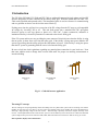
The PVI 3000, PVI 4000, PVI 5000 and PVI 5300 are residential/commercial single phase, grid-tied PV
inverters designed to be inter-connected to the electric utility grid. With this manual the PVI 3000 - PVI
5300 can be installed and operated safely. This installation guide is used as reference for commissioning
and as a guideline on how to use the inverter most effectively.
Feeding power into the grid involves conversion of the DC-voltage from the PV-array to grid compatible
AC-voltage by “inverting” DC to AC. This unit feeds power into a standard 240 VAC split phase
electrical system or two legs (phase to phase) of a 208 VAC, 3-phase commercial, industrial or
institutional facility’s electrical system that is connected to the electric utility grid.
If the PV system and inverter are providing the same amount of electrical power that the facility is using
then no power is taken from or fed into the utility grid. If the facility is using more power than the PV
system is providing, then the utility grid provides the balance of power. If the facility is using less power
than the PV system is generating, then the excess is fed into the utility grid.
Be sure to look into local regulations regarding net metering/inter-connection in your local area. Note
that some utilities need to change their revenue kWh meter for proper net metering measurement or
incentives/billing.
Photovoltaic
Array
PVI 3000-5300
Inverter
Electric Utility
Grid
Fig. 1.1 Grid tied inverter application
The string PV concept
The use of string PV concept significantly reduces the cabling costs on a photovoltaic system. The use of strings of several PV
modules in series and one, two, three (or in some cases four) parallel strings of PV modules has proven advantageous by
delivering a high operating voltage to the solar inverter. This advantage is primarily reflected in a higher efficiency of the
inverter. Careful optimization of the overall inverter system’s cost and efficiency lead to the choice of a 600V DC maximum
system voltage for the power levels of the PVI 3000, 4000, 5000 and 5300 for use with 1kW to 7kW PV arrays per inverter.
Data acquisition, display and communication
5
PVI 3000/4000/5000/5300
Installation and Operation Manual
The integrated data acquisition, display and communication capability of the PVI 3000 - PVI 5300 allows comprehensive
tracking of data for understanding of system performance. All error messages and operating conditions of the PVI 3000 - PVI
5300 as well as the PV system are shown on the display.
These functions allow complete and continuous monitoring of the photovoltaic system. Read-out of data over the integrated
interface and its display is only possible when the solar system is in operation.
An optional full-featured, “inverter-direct” data acquisition and logging gateway and web-based service is available from
Solectria Renewables, called SolrenView (http://www.solrenview.com). You have the option to purchase these services. The
gateway plugs into the inverter and to the facility’s internet service.
Technical structure of the PVI 3000, PVI 4000, PVI 5000 and PVI 5300
A high frequency switching bridge circuit operating in connection with a high frequency transformer provides galvanic
isolation of the photovoltaic system from the building’s AC power (and electrical utility grid). The PV voltage and current are
optimized in such a way that fluctuations which are caused by differing sunlight strengths and PV module temperatures can
still end up producing the maximum possible power.
Internal regulation of the PVI 3000 - PVI 5300 is achieved using microcontrollers, which control the function of MPP
(Maximum Power Point) tracking.
The input PV voltage window is designed to cover a range of 200 to 550 VDC from the PV array (600VDC maximum open
circuit voltage). This means that many combinations of modules and strings from different manufacturers can be used.
The inverter has nearly no standby power consumption and night–time losses (0.5 W). Even when running, the control circuit
power use of the inverter is reduced to a minimum, which helps give the inverter high operational efficiency.
The housing and heat sink for the PVI 3000 - PVI 5300 is manufactured using a heavy aluminium extrusion with an anti-corrosion
finish. The housing is designed to NEMA3 to be resistant to rain and snowfall. The heat sink and fan are designed in such a way
that operation of the inverter is possible at ambient temperatures of -13° F (–25° C) to +131° F (+55° C) at full rated power (at
240VAC or 208VAC – note AC power output is slightly less at 208VAC than 240VAC).
The heat sink serves to conduct away heat generated from energy losses in the power electronics. Internal temperature regulation
provides protection against excessively high temperatures inside the PVI 3000 - PVI 5300. The maximum power processed from
the PV array is automatically reduced to limit excessive inverter temperature.
The PVI 3000 - PVI 5300 will only operate in parallel with the utility grid. AC grid monitoring is done by microcontrollers
configured to meet the requirements of UL1741/IEEE1547. This includes grid voltage or frequency fluctuations outside of the
required limits, anti-islanding and other limitations and requirements, which ensure that the inverter shuts down immediately if the
grid goes down, or if the grid gives surges, sags, changes frequency or otherwise shows signs of instability. If this happens, the
inverter will check the grid and reconnect to the grid 5 minutes after the grid is back to normal. (The display then shows:
“Monitoring”.) Disconnecting from the grid is important to protect the electrical and utility line workers who may be working to
restore the grid as well as electricians working at a site with PV systems.
Power grid faults that will cause the PVI 3000 - PVI 5300 to isolate itself from the power grid:
AC grid voltage
The grid voltage must not go outside the range of +10/-12% of the nominal 240 or 208V AC grid voltage (as per IEEE Std
1547, § 4.2.3). The inverter will isolate itself from the power grid if these limits are exceeded either way. The PVI 3000 - PVI
5300 is factory set to 208 or 240VAC. The inverter will automatically detect and sync to 240 or 208VAC when connected to
the neutral. If it is desired to connect to 208 or 240VAC without a neutral connection, then the inverter must be set at the
factory of adjusted by a qualified installer. A qualified installer can reconfigure the grid voltage setting in the field using
jumper adjustments inside the inverter.
AC grid frequency
The power grid frequency can be within a range of +0.5Hz, -0.7Hz of the nominal 60Hz grid frequency (as per IEEE Std 1547,
§ 4.2.4). The inverter will isolate itself from the power grid if these permitted limits are exceeded either way.
Another important safety feature is galvanic isolation of the utility grid and the PV array as well as ground fault detection and
interrupt (GFDI) of the PV array. The PV array negative is grounded inside the inverter (and must not be grounded at any other
point).
6
PVI 3000/4000/5000/5300
Installation and Operation Manual
8
7
11
5
9
3
10
4
1
6
2
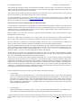
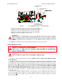
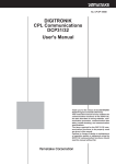
Diagram of the PVI 3000/4000/5000/5300 Features
(1) AC knockouts (and on back)
(2) PV array ground fault interrupt (GFDI) fuse
(3) DC/AC disconnect
(4) DC knockouts (and on back)
(5) Fan assembly (on back at bottom of heatsink, used on PVI 4000/5000/5300 only)
(6) RS-232/485 interfaces
(7) LCD display
(8) LED indicators for basic operating status
(9) Inverter Serial Number
(10) Detachable wiring box
(11) Quick-mount wall plate (behind unit)
Fig. 1.2
PVI 3000/4000/5000/5300 Features Diagram
7
PVI 3000/4000/5000/5300
Installation and Operation Manual
2 Installation
WARNING: Before installing the PVI 3000-5300, read all instructions and caution markings in this manual
and on the PVI 3000-5300 as well as on the photovoltaic modules.
WARNING: Electrical installation shall be done in accordance with all local electrical codes and the National
Electrical Code (NEC), ANSI/NFPA 70.
WARNING: Connecting the PVI 3000-5300 to the electric utility grid must only be done after receiving prior
approval from the utility company and installation completed only by qualified personnel/licensed
electrician(s).
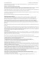
2.1 Checking for Shipping Damage
The PVI 3000/4000/5000/5300 inverters are thoroughly checked and tested rigorously before they are shipped. Even though
they are delivered in a rugged, heavy cardboard box, the inverters can be damaged in shipping.
Please inspect the inverter thoroughly after it is delivered. If any damage is seen please immediately notify the shipping
company. If there is any question about potential shipping damage, contact Solectria Renewables. A photo of the damage
may be helpful.
Do not accept unit if visibly damaged or note visible damage when signing shipping company receipt. Report damage
immediately to the shipping company. Do not remove the unit from packaging. If it is determined that the unit must be
returned, an RMA# must be obtained from Solectria Renewables.
2.2 Inverter Mounting
The PVI 3000/4000/5000/5300 inverter is made up of a sealed NEMA 3 corrosion resistant, painted aluminum enclosure
containing all electrical and electronic components.
NOTE: If the PVI 3000/4000/5000/5300 is mounted outside, make sure the mounting & wiring is completed,
at least to the AC and DC disconnects or junction box(es) in case of rain during the installation process (for
example overnight rain). Since the AC and DC connections are wired to the wiring box, disconnects and or
junction box(es) only, there is no need to open the main inverter enclosure during hook-up. The inverter
enclosure is factory sealed and must NOT be opened at any time in the field as this will void the warranty.
Notes regarding mounting and placement of the inverter
Criteria for device mounting:
Because the inverter is in a NEMA3 enclosure, the inverter can be mounted outdoors.
The very longest life for the inverter can be achieved by mounting it in a clean, dry and cool location even given the unit’s
robust construction and design for efficient cooling. It is recommended to keep the unit out of direct rain. Protection from
a roof overhang, awning is better if the unit cannot be mounted indoors or in a shed, garage or basement.
For optimal electrical efficiency, use the shortest possible AC and DC wires and use the maximum allowable wire size.
(Depending on which model inverter, 8-10AWG minimum (#6 maximum) is recommended for all connections, both AC
and DC.)
Avoid installation in close proximity to people or animals, as there is a small amount of high-frequency switching noise.
Install the inverter in an accessible location following NEC and local codes. Note NEC requirements for clearances and
proximity to other equipment and building walls.
Although not required, installation at eye-height allows easy reading of the indicator LEDs and the LCD display.
8
PVI 3000/4000/5000/5300
Installation and Operation Manual
For optimal inverter life and performance, do not mount the inverter in direct sunlight, especially in hot climates, although
the inverter is designed to function at full power continuously in up to 131o F (55o C) ambient temperatures. In hot
climates if the unit must be mounted in direct sunlight a silver or white metal sun-shield is highly recommended. It is
recommended that the inverter be mounted on the north (or east) side of buildings or on the north side of a PV array
(which can provide some shade). Following these guidelines can help prevent the unit from going into de-rating due to
excessively high inverter case temperature.
In hot climates, the housing and heat sink can reach 160o F (70o C) and must be mounted on an appropriate material for
this temperature as well as one that meets NEC and local codes. The inverter should not be mounted where people are
likely to touch the case or heat sink due to the high potential temperature.
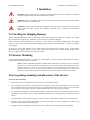
CAUTION: Please follow these guidelines:
The inverter weight is about 47-60 lbs. (21.4-27.3kg) depending on model. Be sure method used for fastening the unit to
the wall will safely hold this weight.
The ambient temperature must be between –13o F (–25o C) and +131o F (+55o C) for full continuous, full power operation.
(The inverter will automatically reduce power or shut down to protect itself if the ambient air temperature rises above
131o F (55o C).) Humidity shall be within 0% and 95%.
The National Electrical Code (NEC) requires that the inverter be connected to a dedicated AC circuit and no other AC
outlets or device may be connected to this circuit. See NEC Section 690.64. The NEC also imposes limitations on the
size of the inverter and the manner in with it is connected to the utility grid. See NEC Section 690.64.
The cooling air enters at the bottom of the heat sink and exhausts at the top of the unit.
recommended clearances for cooling air and space around the inverter.
If you are installing the inverter in a utility vault or electrical closet, the air circulation must be sufficient for heat
dissipation – provide external ventilation, to maintain an ambient condition of less than 131o F (55o C). The ambient
temperature should be kept as low as possible.
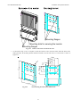
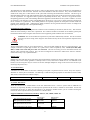
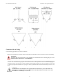
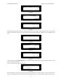
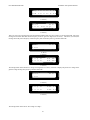
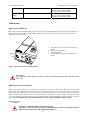
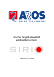
Use the dimensional diagrams below for correct mounting of the inverter.
See diagrams below for
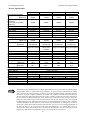
PVI 3000/PVI 4000 DIMENSIONAL DIAGRAM
9.88”
250
4.94”
125 3.7”
94 1.75”
45
145.5
5.75”
70
454
17.75”
732
190
2.75”
7.5”
28.82”
174.2
6.88”
9
PVI 3000/4000/5000/5300
Installation and Operation Manual
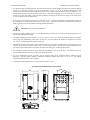
PVI 5000/PVI 5300 DIMENSIONAL DIAGRAM
9.88”
250
4.94” 3.7”
125
94 1.75”
45
6.91”
175.5
70
17.75”
454
732
190
2.75”
7.5”
28.82”
184.2
7.25”
Fig. 2.1 PVI 3000/4000/5000/5300 Dimensional Diagram
Placement and location
·
PVI 3000/4000/5000/5300 inverters that must be vertically mounted may be located indoors or outdoors, given the NEMA
3R rating.
· Avoid mounting the inverter on a location where is exposed to direct rain.
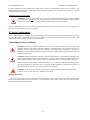
· Leave at least 20” of free space above and 40” below the inverter for best ventilation (see Figure 2.1.1).
· Mount the inverter on a wall that is strong enough to support the 47-60lb inverter.
WARNING!
Some parts of the heatsink can reach temperature over 160F (70℃). Keep flammable, explosive materials
or trash and unknown materials at an appropriate distance from the inverter!
WARNING!
Do not expose the inverter to corrosive liquids and/or gases.
·
·
Keep AC and DC wiring as short as possible to minimize power loss.
Mounting bracket should be fastened to a concrete or a masonry wall using appropriate anchors.
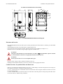
Conduit Locations, Pre-punched Holes and Knock-outs
·
·
·
Holes are pre-punched (and shipped with hole covers) for 1” conduit fittings on the left and right sides of the wiring box,
these holes are centered at 2.5” from the wall mounting surface.
¾” and 1” concentric KOs are on the bottom of the AC and DC sides of the wiring box and these are located 2.63” from
the wall mounting surface.
¾” and 1” concentric KOs are on the back of the AC and DC sides of the wiring box for routing wiring out the back of the
box into the wall for a “hidden wiring” installation.
10
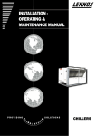
PVI 3000/4000/5000/5300
Installation and Operation Manual
20”
20”
WARNING
RISK OF EL ECTRICAL SHOCK
Norma lly Grou nded Condu ctors May Be
Ungrounde d and Ener gize d When a
Gro und-Fa ult is Ind ic ated."
DO NO T REMO VE COVER. NO USER
SERV ICEABL E P ART S INSIDE. REFER
SERVICING T O QUAL IFIE D SERVICE
PERSO NNEL.
BOTH AC AND D C VO LT AGE SOURCES ARE
TERMI NATED INSIDE THIS EQUIPMENT.
EACH CIRCUIT MUST BE IN DIVIDUALLY
DIS CO NN ECTED BE FORE SERVICING.
WHEN TH E PHOT OV OLTAIC ARRAY IS
EXPOSED TO LIGHT, IT SUPPLIES A DC
VOLTA GE TO TH IS E QU IPMENT.
DO NO T REMO VE COVER U NTIL 5 MIN UTES
AFTER D ISCO NN EC TING A LL S OURCES OF
SUPPLY.
VOLTA GE AND F REQUENCY L IMITS ARE
SET T O TH E CURRENT UL1741 STANDARD
AT TH E TI ME OF SHIP ME NT . RE FE R TO
MANUAL FOR VO LTAGE AN D FREQUENCY
SETTI NG F OR THIS MODEL CHANGES TO
THESE SETTING S CAN BE MADE ONLY BY
AN AU THORIZ ED INS TALLER.
7.5”
7.5”
36” min
wall
GFDI Fuse
For con tinu ed p ro tectio n ag ainst risk of fire,
rep lace only with s ame type and ratings of fuse.
39”
Fig2.1.1
39”
Clearances recommended for PVI 3000/4000/5000/5300 inverter installation
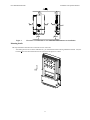
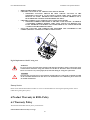
Mounting details
The steps listed below describe how to mount the inverter on the wall:
-
After taking the inverter out of the cardboard box, you will find the bracket in the bag behind the heatsink. First, the
bracket needs to be removed from the inverter as shown in the figure 2.2.1 below.
11
PVI 3000/4000/5000/5300
Installation and Operation Manual
Mounting flanges
Mounting slots for securing the inverter
Mounting flanges
Fig 2.2.1
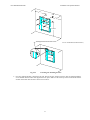
Use the bracket (Fig 2.2.2) as a template to mark the locations on the wall where holes should be drilled. After
drilling the holes, the mounting bracket should be fastened to the wall with screws or screw-anchors as shown in
Figure 2.2.3.
9.88”
98.43
250mm
7.12”
180mm
4.94”
125mm
m
4m
190mm
120mm
70mm
4
1.75”
525mm
1.
Remove the bracket from the inverter
20.67”
4.75”
70mm
2.75”
2.75
in.
7.5”
415.94”
05mm
Fig 2.2.2
The mounting bracket and its dimensions
12
PVI 3000/4000/5000/5300
Installation and Operation Manual
312”
0cm
60cm
22”
312”
0 cm
100~170cm
40”-67”
Thediameter
height ofmounting
the anchor
headrecommended
< 8mm
¼”
screw
or 3/16-1/4” anchor bolt (as shown above)
Fig 2.2.3
Fastening the mounting bracket
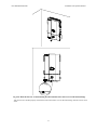
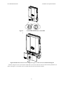
2. Once the mounting bracket is fastened to the wall, then the inverter and the wiring box (that are attached together)
can be hooked onto the bracket and slipped down into place. Make sure the lower lip on the bracket hooks into the
window on the back of the inverter as shown in 2.2.4 below.
13
PVI 3000/4000/5000/5300
Installation and Operation Manual
Slide the mounting bolts at the top of the inverter over the
Slide the
mounting
hooks
on the inverter
hooks
on the
mounting
bracket
over the hooks on the mounting bracket.
flange with
Flange
withslots
mounting
mounting holes
100cm
39" Ensure the inverter is seated
120cm
47"
properly on the mounting bracket
Ground/Floor
Ground/Floor
14
PVI 3000/4000/5000/5300
Installation and Operation Manual
GFDI Fuse
For continued pro tection against risk of fire,
repla ce only with same type a nd ratin gs of fuse.
Fig 2.2.4 Hook the Inverter on the mounting bracket and then fasten with a screw at the bottom flange
After the inverter is hooked properly on the bracket and secured with a screw at the bottom flange, then the inverter can be
wired.
15
PVI 3000/4000/5000/5300
Installation and Operation Manual
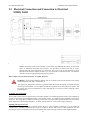
2.3 Electrical Connection and Connection to Electrical
Utility Grid
* Equipment grounds, grounding electrode conductor
and ground fault detector/interrupter not shown
PVI 3000-5300 PV SYSTEM BLOCK DIAGRAM
Fig. 2.3 Simplified electrical connection diagram
Location and Mounting the Inverter
NOTE: Choose the inverter location keeping in mind where any additional disconnects, junction boxes
and/or AC kWh meter (if needed) will be located. One good idea is to mark on the wall (or create a
diagram) where all of the components are to be located. The inverter is set up with integrated AC & DC
disconnects and fused PV combiner to make it very easy and quick to connect the inverter. The fused PV
combiner can also be bypassed using the bypass lug positions.
Refer to Figure 2 for Locations of Features, AC and DC Wires, etc.
WARNING: All electrical installations shall be done in accordance with all local electrical codes and the
National Electrical Code (NEC), ANSI/NFPA 70.
The negative DC photovoltaic connection is grounded within the inverter through the ground fault detection
and interrupt circuit (GFDI). The PV negative should not be grounded at any other point in the system. The
PV positive must never be grounded at any time. (Note that this is reversed for systems using the positive
grounded option.)
AC and DC (PV) Connections:
The PVI 3000-5300 inverters are equipped with covered holes and KOs to fit conduit fittings that are NEC code-compliant for
use with several sizes of rigid and flexible metallic or non-metallic conduit. All conduit and wiring installation is done in the
wiring box. This design allows installation and wiring of the inverter to be done without opening the main inverter enclosure
which should not be opened during installation. AC & DC terminals allow for #10 to #6 AWG copper conductors.
Lightning and Surge Protection:
The inverter is designed with certain protections against surges in voltage including certification to UL1741/IEEE1547
/CSA22.2#107.1 (including ANSI/IEEE 62.41/62.42 as required in the NY SIR), however added protection and solid
grounding provisions are important for best protection against utility surges and surges created by indirect lightning strikes.
16
PVI 3000/4000/5000/5300
Installation and Operation Manual
The installation of a Delta lightning surge arrester or other UL listed arrester of the correct specification is recommended on
both the DC and AC sides of inverter. Solectria and various distributors stock these arresters. They can be installed on the
outside of the wiring box or other locations in the system and wired using the manufacturer's directions. This device gives
important added protection from indirect lightning strikes and resulting surges that provide protection beyond the inverter's
UL1741 requirements. It is suggested to drive a ground rod specifically for the PV array. It is also a very good idea to have
the lightning protection system of the building checked and upgraded if needed before the PV system is installed. (are there
air conductors / rods along the roof line of the building above the PV array? Do you see a copper ground wire running from
the air conductors to a ground rod?) These added protections are especially important for areas prone to thunder storms and
possible nearby lightning strikes. Although these added precautions will not guarantee that there will be no damage from
lightning, they can help prevent or limit potential damage.
Grounding Electrode Conductor:
As with all PV systems, a Grounding Electrode Conductor must be installed per NEC690.47 (and 250.166). This conductor
should be sized according to these NEC requirements. This conductor should be terminated on the labeled ground point
located at the bottom of the wiring box where the DC and AC equipment ground conductors also are terminated.
WARNING: The inverter should not be opened at any time unless authorized by Solectria. The unit is sealed at
the factory and its UL listing will no longer be valid and the warranty will be void if opened or tampered with in
any way.
AC Voltage:
The PVI 3000-5300 are 240V AC grid connected devices. They are also both suitable for 208V AC grid-connected use. For
example, connection to 2 phase legs of a 208V AC, 3-phase service (where acceptable by code). No unit (PVI 3000, 4000,
5000, or 5300) can be used with just a 120V AC connection. The units are factory pre-set for auto-detect 240VAC and
208VAC when connected with a neutral. They can also be configured for connection to either 240 or 208 VAC without a
neutral at the factory or by a qualified installer.
Multiple Units:
Multiple PVI 3000-5300 units can be used at the same location/facility assuming all codes are followed including NEC, local
building codes and area utility guidelines. If multiple units are used, each inverter should have its own dedicated circuit
breaker, and a PV string must only be wired to one inverter (although multiple PV strings can be used on each inverter up to
unit ratings and power levels).
AC Circuit Breakers:
A dedicated AC circuit breaker in the home or building circuit panel is required for the PV inverter. Every PVI requires a
208/240V AC rated 2–pole circuit breaker. The following is a table showing the appropriate circuit breaker for the PVI 3000,
4000, 5000, and 5300 (based on number of Amps).
PV Inverter Model
Circuit breaker used (Amp)
PVI 3000
20A
PVI 4000
20 or 25A
PVI 5000
25 or 30A
PVI 5300
30A
AC and DC Disconnects:
AD & DC disconnects are standard features of the PVI 3000-5300 inverters. If the PV system needs an additional AC
disconnect (as required by the utility or local inspector) separate from the inverter or outdoors it can be added. If local code
requirements call for the AC and/or DC disconnect(s) to be mounted in another location, you can consider relocating the
inverter also to the required location to provide the AC or DC disconnect.
Suggested additional AC Disconnect (if needed): 240V AC, 30A, 2 Blade, NEMA 3R
Rain-proof NEMA 3R, no fuse
Rain-proof NEMA 3R, fusible*
Rain-proof NEMA 3R, fusible
Rain-proof NEMA 3R, no fuse
Part Number
DU22IRB
D221NRB
TG3221R
TGN3321R
Manufacturer
Square D
Square D
GE
GE
Pull-out disconnect, 3R, no fuse
3800
Millbank
* Fusible AC disconnect available on integrated panel assembly.
17
PVI 3000/4000/5000/5300
Installation and Operation Manual
For some installations, code compliance may include indoor, NEMA 1 rated disconnects which are less expensive. For
whichever disconnect is selected, you will also need the proper listed ground bar kit. (No neutral kit is needed, as no neutral
line should enter the disconnect.)
Connecting the AC Inverter Wiring:
WARNING: The wiring of the PV inverter’s AC and DC connections must only be done with the building
AC circuit breaker off and the PV array disconnected or covered with an opaque material (or other method to
assure the PV wiring is not live). Both AC and DC should be disconnected or turned off.
The PVI 3000-5300 inverters are not capable of back-feeding currents into the PV array from the AC source including into
short circuit(s) or fault(s) in the PV array or string(s).
PV String Configurations:
There is a huge number of PV module string combinations that will work well with the PVI 3000-5300 inverters given the
very large DC voltage range in which the inverter can operate. See string sizing in Appendix B for some examples. This
appendix also refers to a complete string sizing resource online.
Connecting the Inverter Wiring:
WARNING: Follow PV module manufacturer’s directions. PV-arrays produce electrical energy when
exposed to light and could create a hazardous condition. (One method used to assure safety from shock is to
completely cover the surface of all PV-arrays with opaque / dark material before wiring them.) Alternatively,
keep all PV module connectors disconnected (but don’t leave PV module connectors open in rainy weather or
when leaving the jobsite.)
WARNING: Before connecting the connectors of the PV-panel to the DC inverter terminals, check the correct
polarity and admissible PV-panel voltage between the (+) and the (-) cable connectors of the PV panel. (Note
that the mating connectors used to connect to your array junction box may have reversed polarity markings.)
The PV-panel open circuit voltage must be below 600V DC (Vpv < 600V DC) under all conditions as per NEC
690-7 using multiplier for cold weather OCV, or using PV module manufacturer’s specifications. Please read
the Technical Info section and see PV string sizing table in Appendix B.
WARNING: Even when in the off position, the fused PV combiner and the DC disconnect terminals will
remain live on the PV side when the PV modules are in daylight.
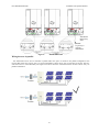
Wiring the inverter
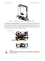
The cover of the wiring box needs to be removed before wiring the inverter. First the DC/AC disconnect switch shall be
turned to the OFF position as shown in the Figure 2.3.1. and then remove the 4 screws; remove the cover of the wiring box
shown in the figure 2.3.2 and 2.3.3 below.
18
PVI 3000/4000/5000/5300
Installation and Operation Manual
OFF
ON
Fig 2.3.1
Turn the DC/AC disconnect switch OFF
Fig 2.3.2 Remove the 4 screws on the wiring box Fig 2.3.3 remove the cover from the wiring box
`
After the wiring box cover is removed, the conduit hole covers can be removed (or KOs in other locations punched out) as
shown in the figure 2.3.3 for the DC and AC conduits which will enter and exit these locations.
19
PVI 3000/4000/5000/5300
Fig 2.3.3
Installation and Operation Manual
Remove the hole covers where the conduits will enter and exit.
The following three sections describe the wiring for the AC, DC, and communication ports. The AC and DC wiring shall be
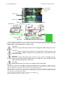
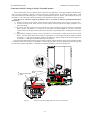
done in the wiring box of the PVI 3000/4000/5000/5300. There is a pair of DC terminal blocks, DC fuse, a bypass terminal
block, two (2) RJ-45 connectors, and one (1) AC terminal block in the wiring box as shown in the Figure 2.3.5. The DC
terminal blocks are used to connect up to 4 PV strings that will parallel connected in the wiring box (3 strings for the PVI
3000), or the fuse bypass terminal can be used if the fused combiner feature is not needed. The RJ-45 connectors are used for
external communication to a remote computer or communication gateway. The AC terminal block is used to connect to the
building/utility grid through a circuit breaker in the building distribution panel.
Fuse bypass terminal(s)
1
Negative ground
1
Positvie ground
PV String Fuse
AC Terminal Block
Ground Bar
GFDI Fuse
RJ45-R
RJ45-L
Fig 2.3.5
Wiring box bottom view
WARNING!
All electrical work shall be done in accordance with the local and national electrical codes and with
the National Electrical Code (NEC), ANSI/NFPA 70 and should follow the important safety
instructions in this manual.
20
PVI 3000/4000/5000/5300
Installation and Operation Manual
WARNING!
The National Electrical Code (NEC) states that the inverter must be connected to a dedicated circuit,
and that no other outlets or devices can be connected to the same circuit. The NEC also imposes
limitations on the size of the inverter and the manner in which it is connected to the utility gird.
WARNING!
Make sure that you use suitable conductors for both the AC and DC wiring. The cables must be
adequately sized and of correct temperature rating and sunlight resistant if needed. Use #10 AWG to
#6 AWG, 90 C (194 F) copper wire for all AC and DC wiring connections to the PVI
3000/4000/5000/5300 inverter.
WARNING!
PV arrays will be energized when exposed to light. Cover the arrays with opaque (dark) materials
during installation and wiring, and/or keep module leads disconnected.
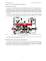
Before wiring the PVI 3000-5300 inverter, the installer needs to determine the grid connection/ utility configuration that
the inverter will be connected to. The PVI 3000-5300 inverter is default set for utility interconnection with a neutral
connection. However, it may be reconfigured for a connection without a neutral. The utility configuration jumpers, J210, are
located on the control board as shown in the figure 2.3.6 are used to set the PVI 3000-5300 inverter to be connected to the
commonly used utility configuration types shown in the figure 2.3.7. As shown in the figure 2.3.6, the P1 and P2 pins are
used to configure the PVI 3000-5300 inverter for the connection types of 208 V and 240 V AC outputs with or without
neutral. When the inverter is set for the connection configurations with neutral, it can automatically distinguish the utility
voltage and adjust the output AC voltage according the grid voltage.
Note: When connecting the PVI 3000-5300 inverter to the building / utility, the voltage must be
compatible.
P1
P2
P3
P1
P2
P3
J210
Fig 2.3.6 Building/Utility configuration jumpers
21
PVI 3000/4000/5000/5300
Installation and Operation Manual
Fig 2.3.7 Utility configurations
Connection of the AC wiring
Use the following procedure to wire the AC conductors.
Open the circuit breaker box and switch off the circuit breaker box that will be used to connect the inverter to the building.
WARNING!
Reconfirm that the circuit breaker to the grid/utility is switched OFF before connecting the power wires
from the breaker to the inverter AC terminal block.
·
Use #10 AWG to #6 AWG, 90 C (194 F) copper wire for all AC wiring connections to the PVI 3000/4000/5000/5300
inverters. You must choose the appropriate wire size based on NEC code requirements and we recommend designing not
more than 2V drop (1%) at the most. Larger conductors will be needed for longer wire runs. For example, you may need
to splice up to larger than #6AWG if a very long run such as greater than 200’ with a PVI 5300 to keep to the 2V (1%)
drop.
CAUTION!
To ensure that the total impedance of the grid plus the interconnection AC power cable shall be less
than 0.18Ω for PVI 3000, 0.12Ω for PVI 4000, 0.10Ω for PVI 5000, 0.09Ω for PVI 5300. These values
are based on a ~2VAC drop or ~1% AC loss.
22
PVI
P 3000/40000/5000/5300
Installlation and Opperation Manuual
L1 wire con
nnected to
L1 terminal
L2 wire conn
nected to
L2 terminal
N terminal
Equipment ground wire
connected to
o ground bar
Fig 2.3.8
·
·
·
·
·
AC Termin
nal Block forr AC cable connections
c
Connnect the AC eq
quipment GND
D wire to the screw
s
of the ground
g
bar labbeled
Connnect the white N wire to the terminal labeeled N of the AC
A terminal block.
Connnect the L1 wirre to the termiinal labeled Line1
L
of the AC
C terminal bloock.
Connnect the L2 wirre to the termiinal labeled Line2
L
of the AC
C terminal bloock.
Tightten the screwss with a torquee of 15.6 in-lbb (1.7Nm)
WARNING!
W
E
Each connecttion to a PVI 3000-5300 in
nverter must be installed with
w a dedica
ated circuit brreaker with 20-30
2
aamperes (dep
pending on in
nverter modeel) maximum
m branch circcuit over current protectiion in accord
dance
w
with the Natiional Electricc Code, ANS
SI/NFPA 70. No other ap
ppliances maay be conneccted to the ciircuit
b
breaker.
·
Reconfirm
m that all connnections are coorrect as descrribed above annd all screws are properly tightened.
Connection
C
n of the DC wiring
W
WARNING! EXTREME SHOCK AN
ND FIRE HAZ
ZARD!
R
REMOVE AL
LL PV STRIING FUSES BEFORE WIRING
W
DC CONNECTIO
C
ONS! DO NOT REINST
TALL
F
FUSES UNTIL YOU AR
RE READY TO COMM
MISSION TH
HE INVERTE
ER (SEE CO
OMMISSION
NING
S
SECTION AN
ND PROCDU
URE).
W
WARNING!
D
DO NOT USE
E FUSES LA
ARGER THAN 15A FOR THE
T
PV STR
RING FUSES
S!
w
box, RE
EMOVE ALL
L PV STRIN
NG FUSES BE
EFORE WIR
RING
Before aany DC wiringg is attemptedd within the wiring
DC CONNE
ECTIONS.
The wirinng box of the PVI 3000-5300 inverter is designed withh a pair of thee DC terminal blocks whichh support up to
o four
(4) independdent PV stringgs to be fused and connecteed in parallel iin the wiring box
b and then fed into the innverter (or 3 in
i the
case of the P
PVI 3000). Th
he PVI 3000-55300 inverter is shipped witth up to four (4)
( 15A, 600V
Vdc PV string fuses in the wiring
w
box for the PV strings. However,
H
thee size of the PV
P string fusees shall be deetermined by the electricall ratings of thhe PV
module and by UL and National
N
Elecctrical Code (NEC)
(
requireements. IN NO
N CASE SHALL
S
FUSE
ES OF LAR
RGER
THAN 15A BE USED FOR
F
THE PV
V STRING FUSES.
F
Pleasse refer to Figgure 5.2 for th
he replacemennt of the PV string
s
fuses. 15A fuses are shippped standard with every innverter unlesss other values are specifiedd at the time of
o order. 8, 100 and
12A values aare also available from thee factory. Thee fused combiiner also is abble to be bypaassed using thhe provided by
ypass
terminals (2 positions).
There aree two (2) term
minals, labeledd “Ungroundeed (+)” and “G
Grounded (-)”,, per PV string
g located in thhe wiring boxx used
for the DC connections as
a shown in Figure
F
2.3.9 The
T DC equippment groundd wire shall be
b connected to a screw on
o the
l
ground bar labeled
15.6 in-lb (1.7Nm)
inn the wiring box
b of the PV
VI 3000-5300 inverter. All the
t screws shaall be tighteneed with a torqque of
23
PVI 3000/4000/50000/5300
Installatio
on and Operattion Manual
Connect to PV
V+
if fuse bypasss is
desired
Coonnect to PV+
+
Coonnect to PV-
Fig 2.3.9
DC terminaal blocks forr DC wiringg connection
ns
Figg 2.3.10
PVI 3000 su
upports onlyy three (3) PV
V string fusess
The PVI 30000 is shipped with
w three (3)) 15A, 600Vdcc PV string fuuses as shown in the Figure 2.3.10, abovee; therefore, thhe
fou
urth pair of tterminals (froom left) shall not be used
d to connect to
t a PV strinng. IN NO CASE
C
SHALL FUSES OF
O
LA
ARGER THA
AN 15A BE USED
U
FOR THE PV STRIING FUSES.
C
CAUTION!
P
PV arrays aree energized when
w
exposed to light. Use safe workingg practices wh
hen working on PV arrayys.
C
CAUTION!
P
Polarities
of each
e
DC input voltage frrom a PV strring shall be connected coorrectly to th
he
““+” (positive)) and “–” (neegative) term
minals of a pair respectivvely. The DC voltage musst be less tha
an
6600V in any condition.
c
CA
AUTION!
Th
he inverter is listed for no
n backfeed current into the PV arraay. However, the ampaccity of the PV
strrings must be
b calculated when determ
mining propeer PV combiiner fuse vallve to preven
nt fire hazard
d.
(T
The combined
d maximum PV
P input currrent is 25A)
CA
AUTION!
Th
he maximum PV input current to the inverter
i
usingg fuse bypasss terminal is 25A.
2
·
·
·
·
The
T positive ((+) wire of thhe DC input shhall be conneected to the teerminal labeleed “Ungroundded (+)” and the
t negative (-)
(
wire
w of the DC
C input shall be connectedd to the termin
nal labeled “G
Grounded (-)””, except wheen using positively groundeed
modules.
m
In thhat case, see Appendix
A
D att the end of thhis manual forr further instru
uction.
Wire
W nuts shalll not be used to join any wires together or
o to make anyy connectionss anywhere in the PV system
m except wherre
acceptable
a
by code. Wire nuts
n are a freqquent cause off unreliable coonnections, resistive connecctions, and groound faults annd
are
a not allowed in certain appplications byy NEC.
Connect
C
the eqquipment grouund wire to thee screw of thee ground bar laabeled
.
Tighten
T
the scrrews with a toorque of 15.6 in-lb
i
(1.7Nm).
24
PVI 3000/4000/5000/5300
Installation and Operation Manual
WARNING!
Route the DC wires to the PVI 3000-5300 inverters away from any possible hazards that could damage to
the wires (such as sharp corners, edges or near covers where wires could be pinched or crushed).
WARNING!
Hazardous voltage is still present on the inverter after disconnection of all PV DC inputs. Allow 5 minutes
for the inverter to discharge the DC voltage completely.
·
There are up to four (4) independent PV strings (4 pairs) can be connected to the PVI 4000-5300 inverter as shown in the
figure 2.3.11. The PV strings will be connected in parallel in the wiring box. Therefore, these four (4) PV strings shall be
the same capacity (or at least the same total voltage).
Bypassing Fused Combiner
If no (fused) combiner is required, as in the case of a fused combiner on the roof with the PV array, then the fused
combiner in the PVI 3000-5300 can be bypassed by using the “Ungrounded (+)” bypass terminals (2) to the right of fuses.
Up to 2 PV circuits can be connected (2 lugs). The “Grounded (-)” connections still are to be connected to the “Grounded
(-)” terminal block.
PV+
N
L2
L1
PV-
Fig 2.3.11
PV- String connections and AC connections
2.4 Connection of Communication wiring
The PVI 3000-5300 inverter supports two common data interface standards, RS-232 and RS-485 that will be used to
communicate to the remote computer or communication gateway. Only one of the communication interfaces can work at a
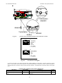
time. As shown in the Figure 2.4.4, there are two RJ-45 connectors, RJ45-R and RJ45-L that are located on the bottom of the
wiring box. The pin numbers of the RJ-45 connectors and the corresponding signals are described in the Figure 2.4.2 below.
If the RS485 is used as the external communication interface and the inverter is the last device in the RS485 loop, then the
termination switch shall be put to ON position (shown in the figure 2.4.3). The installer needs to open the front cover of the
wiring box to switch the termination switch to ON position. The termination switch is default set to OFF position.
25
PVI 3000/4000/5000/5300
Installation and Operation Manual
Termination
ON/OFF
RS232
Termination
RJ45-L
Fig 2.4.1
RJ45-R
positions of the communication ports and termination switches
RJ45-L
8
1
Top view
RJ45-R
8
1
Top view
Fig 2.4.2
Pin
1 TXD (RS232)
2 RXD (RS232)
3 Not used
4 GND
5 GND
6 Not used
7 TX A (RS485)
8 RX B (RS485)
Pin
1 Factory reserved
2 Factory reserved
3 5V
4 GND
5 GND
6 5V
7 TX A (RS485)
8 RX B (RS485)
RJ-45 Pinouts and Signals
As shown in the Figure 2.4.2, the RS-232 signal pins, TXD and RXD, are in the RJ45-L connector. Therefore, only the
RJ45-L can be used to connect to the remote PC or terminal when the RS-232 interface is selected. If RS-485 interface is
selected, both RJ-45 connectors will be used for the daisy-chained / cascaded RS-485 connections shown in the Figure
2.4.3.
Standard Cables available for RS232 & 485 communication
Description
Part Number
Typical Use
Cable, RS485 comm. PVI 3000-5300
WIH-020082
RS485 cable for communication gateways
Cable, RS485 daisy chain PVI 3000WIH-020081
RS485 jumper cable, for 3000-5300 inverter-to5300
inverter
26
Length
7 ft
30 in.
PVI 3000/4000/5000/5300
Installation and Operation Manual
WIH-020081
RS485 Daisy
chain
To gateway or
computer
WIH-020082
Fig 2.4.3
RS-485 connection
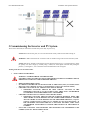
Wiring inverters in parallel
PVI 3000-5300 inverters can be connected in parallel when more power is needed. In the parallel configuration, each
inverter shall connect to its own PV array. It is not recommended to connect one PV array to more than one inverter. This may
cause the inverter to work abnormally. The Figure 2.4.4 below shows the connections between inverters and PV arrays in
parallel configuration.
27
PVI 3000/4000/5000/5300
Installation and Operation Manual
Fig 2.4.4
Parallel configuration of inverter
3 Commissioning the Inverter and PV System
The inverter is mounted, all connections are made and you are ready to power it up.
NOTE: Make sure all tools; parts, etc. are removed from the vicinity of the inverter before turning on.
WARNING: Make a final check for correctness of all AC and DC wiring to the inverter and in the system.
NOTE: With the PV modules connected and inverter disconnects still off, it is a good precaution to check
PV polarity once more simply by carefully using a 1000V, DC rated digital volt meter and probing the
positive (+) and negative (-) PV connections on the terminal blocks in the wiring box.
Turning on the inverter for the first time:
STOP! CHECK YOUR WIRING:
WARNING! EXTREME SHOCK AND FIRE HAZARD!
FAILURE TO FOLLOW THE FOLLOWING PROCEDURE CAN RESULT IN SERIOUS SHOCK,
FIRE DAMAGE AND WILL VOID INVERTER WARRANTY!
o
o
o
o
o
REMOVE WIRING BOX COVER
PV STRING FUSES SHOULD NOT BE INSTALLED AT THIS POINT (If they are installed, STOP!
and see the section “Replacing PV Fuses” in the Maintenance section at the end of this manual)
CHECK DC VOLTAGES OF ALL STRINGS USING 600V DC METER
MEASURED VOLTAGES SHOULD BE OPEN CIRCUIT VOLTAGE; IF THE
MEASURED VOLTAGE IS AT OR CLOSE TO 0.0V, THEN STOP! AND RECHECK
YOUR WIRING TO ENSURE THERE IS NOT A DEAD SHORT.
CHECK DC POLARITY OF ALL STRINGS USING 600V DC METER
MEASURED VOLTAGES SHOULD INDICATE POSITIVE READINGS WHEN THE
“RED” PROBE OF YOUR METER IS ON THE UNGROUNDED TERMINAL AND THE
“BLACK” PROBE OF YOUR METER IS ON THE GROUNDED TERMINAL (except for
positively grounded systems, in which case see Appendix D at the end of this manual). IF
THE MEASURED VOLTAGES INDICATE A NEGATIVE POLARITY, THEN STOP!
AND RECHECK YOUR WIRING TO ENSURE THE POLARITY OF THE STRINGS IS
CORRECT.
ONCE THE VOLTAGES AND POLARITIES ARE MEASURED AND CONFIRMED TO BE
CORRECT, INSTALL THE PV STRING FUSES.
28
PVI 3000/4000/5000/5300
Installation and Operation Manual
Turn on the dedicated 2-pole circuit 240/208VAC circuit breaker on the home/building electrical panel
Turn on the system AC disconnect (if the system is equipped with additional AC disconnect)
Turn on the DC/AC disconnect on the inverter.
Watch the LED indicators for initialization (all three LEDs on) and LCD messages.
Watch for blinking green LED and LCD messages indicating 5 minute connect to grid time and following this time,
the inverter will be on-line and beginning to feed power into the AC circuit, the inverter is operating normally
Last, look for a steady green LED indicating the inverter has stabilized at Maximum Power Point
See LCD section (4) of manual for detailed description of messages and indications.
Operation:
The control electronics will be active as soon as DC (PV) voltage reaches 200VDC. The inverter will go on-line with the
utility/building grid when the DC voltage first exceeds 235VDC (strike voltage). Next, the inverter will load the array,
bringing the DC voltage down from 235VDC to no less than 200VDC.
Once there is enough PV power at 200VDC to back feed AC power switching will automatically feed power to the grid. (The
inverter will always wait 5 minutes after being turned on and being within proper grid voltage range, before going into gridfeed mode).
Because the inverter goes completely off line at night or in dark conditions when no power can be produced, the standby losses
are less than 0.5 Watt, adding additional energy production annually compared to some competitor’s inverter designs that
remain on all the time.
Operating states, GFDI status and error indications shown by the LED indicators, and data, mode and error codes are shown
by the LCD display which are described in chapter 4, “Power, GFDI, Error LED Indicators and LCD Display”.
4 Power, Ground Fault, Error LED Indicators and LCD Display
The inverter operates automatically without the need for user interaction or maintenance.
The PVI 3000-5300 automatically starts feeding AC power into the grid every morning as the sun rises, as soon as sufficient
DC voltage and PV power is available. The inverter microcontroller runs through various checks before going online with the
grid and feeding power into the grid.
29
PVI 3000/4000/5000/5300
Installation and Operation Manual
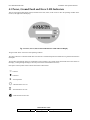
4.1 Power, Ground Fault and Error LED Indicators
There are three light-emitting diodes (LEDs) mounted on the front (center) of the inverter to show the operating condition of the
inverter (to the right of the LCD display).
Fig. 4.1: Power, Error, and Ground Fault Indicator LEDs and LCD Display
The green LED "Power" shows the current operating condition.
The yellow LED "Error" indicates whether there is an internal or external fault present and whether the AC grid back-feed has been
interrupted.
The red LED "Ground Fault" shows if a ground fault is present. (If there is any ground current measured the value can be shown on
the display, scrolling through the display is necessary to locate the Ground Fault current value)
Description of LED symbols used to indicate LED status in this manual
○
●
x
☼
¤
: LED ON
: LED OFF
: Inconsequential
: LED ON/OFF 0.9/0.1 Sec
: LED ON/OFF 0.1/0.9 Sec
: LED ON/OFF 0.25/0.25 Sec
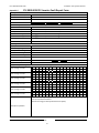
LED Indication Table
LED indicators
Operating Status
30
Description
PVI 3000/4000/5000/5300
Green
Yellow
Red
Green
Yellow
Red
Green
Yellow
Red
Green
Yellow
Red
Green
Yellow
Red
Green
Yellow
Red
Green
Yellow
Red
Green
Yellow
Red
Green
Yellow
Red
Green
Yellow
Red
Green
Yellow
Red
Installation and Operation Manual
Initialization
The PVI 3000-5300 inverter is in
initialization.
System Check mode
The inverter is in System Check
mode.
Monitor mode
The inverter is in Monitoring mode.
Grid/MPP mode
The inverter is in Grid Feeding mode.
De-rating
Power de-rating is performed.
Warning
Warning is detected.
Low Insolation
The inverter is in low insolation.
Fault mode
The inverter is in Fault mode.
Ground Fault
Ground fault detected.
Idle mode
The inverter is in Idle mode.
Night Time
There is no DC power coming from
PV array. System is powered off.
31
PVI 3000/4000/5000/5300
Installation and Operation Manual
4.2 The LCD Display
The PVI 3000-5300 inverter is supplied ready to operate so there are no settings, which need to be made by the user for fully
automatic feeding of power into the grid. The device comes standard with an LCD display on which various data can be read.
All indicated data is only an indication and has tolerances of up to 5%.
The PVI 3000-5300 inverter has a 16 x 2 LCD to show the operating status, input/output data, and error messages. As long
as the DC input voltage is above the pre-set threshold value, the LCD continues to display the information following the
process flow illustrated in the Figure 4.2.1.
The process flow may follow the operating mode, fault mode, or idle mode. The operating mode is when the system goes
from power-on to system check, monitoring, and then grid feeding mode without any fault condition detected. The inverter
is should work following the operating mode and eventually feeds the power to the grid. During the system check and
monitoring mode, if a fault condition that could be cleared automatically is detected, then the system will go into the fault
mode that the system could return to the operating mode once the fault condition goes away. One obvious example is that an
“island” condition is detected due to the grid going off and then back on later, the fault condition is cleared when the power
returns. If a fault cannot cleared on its own, then the system will enter the idle mode and will need a service person to clear
the fault and reset the system. These three modes are illustrated in the Figure 4.2.1.
The following figures explain how the display works in the operating mode.
When the DC input voltage goes above the pre-set threshold value, the inverter is powered up and will show the company
name and model name (PVI 4000 in this example) on the LCD as shown below.
S O L E C T R I A
P V I
4 0 0 0
After 3 seconds, software versions of two embedded CPU’s, Sequential and Current controllers, will be displayed on the LCD.
Afterward, the serial number (S/N), the baudrate (BR) / address (ID) for the communication port will be displayed..
S E Q
V e r s i o n
X . XX
CUR
V e r s i o n
X . XX
3 seconds ↓
S / N
B R
XXXXXXXXXXXX
XXXXX
I D
XXX
3 seconds ↓
And then three (3) seconds later, it displays the setting of the nominal grid voltage configuration. The grid type setting of
208/240 with neutral is used as the display example shown below. For the grid type setting, please refer to section 2.3 Wiring
the Inverter.
G r i d
L 1
Ty pe
12 0V
L 2
1 2 0 V
3 seconds ↓
If the grid type is set to 240 Vac without neutral, then the display will be looked as the figure shown below.
32
PVI 3000/4000/5000/5300
Installation and Operation Manual
G r i d
T y pe
L 1 - L 2
2 4 0 V
3 seconds ↓
And then three (3) seconds later, LCD will show the voltage setting for the inverter to drop the grid connection. The settings
of the Vl-nH and its clearing time will be displayed. The Vl-nH setting is the phase-to-neutral (rms) high threshold voltage
setting at which point the inverter disconnects its output from the AC power grid when abnormally high phase-to-neutral AC
voltage is detected. After the setting of the Vl-nH is displayed, the setting of the Vl-nL will be displayed for 3 seconds.
V l - n H
C l r
t
XXX . XV
<
XXX
C y c s
3 seconds ↓
V l - n L
C l r
t
XXX . XV
<
XXX
C y c s
3 seconds ↓
Three (3) seconds later, it displays the setting of the VacH which is the phase-to-phase (rms) high threshold voltage setting at
which point the inverter disconnects itself from the grid when abnormally high phase-to-phase AC voltage is detected. Also,
the setting of the clearing time which is the total duration of time to disconnect the output from the AC grid is displayed. The
clearing time is the summation of the de-bounce time and the hardware delay time. This delay is necessary to avoid nuisance
trips. After the settings of the VacH and its clearing time, the settings of the VacL and its clearing time will be displayed for
three (3) seconds. The display Vl-nH/Vl-nL is only for 208/240 with neutral setting, VacH/VasL is only for 240 or 208
without neutral, they would not display at the same time.
V a c H
C l r
XXX . XV
t
<
XXX
C y c s
3 seconds ↓
V a c L
C l r
XXX . XV
t
<
XXX
C y c s
3 seconds ↓
Then the high and low threshold settings of the AC frequency and the clearing time will be shown for three (3) seconds. When
the AC frequency reaches the high or low threshold setting, the inverter will disconnect its output from the AC grid.
F a c H
C l r
XX . XXH z
t
<
XXX
3 seconds ↓
33
C y c s
PVI 3000/4000/5000/5300
Installation and Operation Manual
F a c L
C l r
XX . XXH z
t
<
XXX
C y c s
3 seconds ↓
Then the LCD will display the setting of the AC high voltage limit above which value, inverter will reduce the output power
until the AC voltage drops within this setting. If the grid type is set to 208/240 with neutral, then the display will be looked
as the figure shown below.
V a c H
L i m i t
L - N
XXX . XV
3 seconds ↓
Then the setting of the re-connection time will be displayed. The re-connection time is the duration of delay time for the
inverter to re-connect to the grid after the fault(s) is(are) cleared.
V p v S t a r t
R e c o n n e c t
XXX . XV
XXX s
3 seconds ↓
Waiting Mode Display
After the basic information of the inverter is displayed, the system enters the System Check mode which is indicated on the
LCD.
M o d e
S y s t e m
C h e c k i n g
During the system checking, if the DC input voltage is not reaching the point of the PV start voltage setting, , then the
following message will be shown on the LCD and the system will stay at this step.
L o w
I n s o l a t i o n
During the system checking, if the grid is not connected to the inverter, then the inverter enters the fault mode and the
following message will be shown on the LCD.
M o d e
G r i d
F a u l t
NA
Once system check is done, the inverter goes into the monitoring mode. If all data needed for grid feeding is in the acceptable
range, the system will keep monitoring this data for a period of time. The following information tells users that the system will
go into the grid feeding mode in XXX seconds and then show the measured data of the DC input voltages and the existing
voltage and frequency on the grid side.
34
PVI 3000/4000/5000/5300
Installation and Operation Manual
M o d e
Mo n i t o r i n g
N e x t C o n n e c t
XXX s
3 seconds ↓
Vp v
XXX
V
3 seconds ↓
V a c
XXX . XV
F a c
XX . XH z
3 seconds ↓
During the monitoring mode, if DC input voltages fall under the PV start voltage setting, the system stays in this mode and
shows the information as follows. The system will still keep measuring the parameters of both DC and AC and display on the
LCD.
M o d e
Mo n i t o r i n g
L o w
I n s o l a t i o n
3 seconds ↓
V p v
XXXV
3 seconds ↓
V a c
XXX . XV
F a c
XX . XH z
3 seconds ↓
After the system enters the grid feeding mode, it will show the following information in order and repeat this until the system
goes to another operating mode.
The first screen shows the current operation mode.
M o d e
G r i d / MP P
3 seconds ↓
The next messages are the up-to-minute data of the DC input voltages and the AC output voltage. The first two messages are
for the PV array and the other two messages are for the AC output power. Vpv is the incoming voltages from the PV array.
35
PVI 3000/4000/5000/5300
Installation and Operation Manual
Wpv is the incoming power of the PV array in Watts. Vac, Pac, Iac, and Fac are the voltage, power, current, and frequency
that the inverter feeds to the grid.
V p v
XXXV
Wp v
X X X XW
3 seconds ↓
V a c
XXX . XV
P a c
X X X XW
3 seconds ↓
F a c
XX . XH z
I a c
XX . XA
3 seconds ↓
The next message shows the cumulated energy in kWh and period of time in hours for the inverter delivering the power to the
grid since the inverter has been power on and operated for today.
E t o d a y
XXX . X
H t o d a y
XX . X
k Wh
H r
3 seconds ↓
The next message shows the cumulated energy in kWh and period of time in hours for the inverter delivering the power to the
grid up-to-date since the inverter has been installed and operated.
E a c
H
XX XXXX . X
X X XX X
k Wh
H r
3 seconds ↓
There are five possible de-rating displays which will be shown if power de-rating is detected in grid feeding mode. Only one
occasion that causes de-rating could be detected at a time. Therefore, only one of the following messages will be displayed if
power de-rating occurs. When Temp message is presented, the power de-rating is caused by the over temperature. The Ipv
message shows that the power de-rating is caused by restricting the DC input current to the maximum limit. The Iac and Pac
messages illustrate the power de-rating is caused due to restriction of the maximum output AC current and power. The VacH
message shows that the power de-rating is caused by the high AC voltage.
M o d e
D e r a t i n g
T e m p
36
PVI 3000/4000/5000/5300
Installation and Operation Manual
M o d e
D e r a t i n g
I p v
M o d e
D e r a t i n g
I a c
M o d e
D e r a t i n g
P a c
M o d e
D e r a t i n g
V a c H
There are three possible warning messages that may be displayed with different failures. These messages occur in grid
feeding mode. When EEPROM message is displayed, the system is unable to access the EEPROM. The COMM message
means a failure of the communication function. The FAN BLOCK message shows that the fan has stopped running. These
warnings could appear one after the other.
W a r n i n g
E E P R OM
W a r n i n g
C O MM
W a r n i n g
FA N
B L OC K
The messages for the fault mode are as follows. It shows the fault mode, serial number of the inverter, software versions of
the sequential and current controllers and then the error messages which are listed in the Error Message Table on section 4.1.
Mo d e
S / N
F a u l t
XXXXXXXXXXXX
3 seconds ↓
37
PVI 3000/4000/5000/5300
Installation and Operation Manual
S E Q
V e r s i o n
X . XX
CUR
V e r s i o n
X . XX
3 seconds ↓
M o d e
e r r o r
F a u l t
m e s s a g e
3 seconds ↓
There are several error messages that show the detailed conditions that cause the system to go into the fault mode, such as the
messages shown below that show that the frequency of the AC grid is too high (H) or too low (L). After three (3) seconds, the
message shows the present frequency and the frequency that caused the system to go into the fault mode.
M o d e
F a u l t
F a cX
X: H or L
3 seconds ↓
T r i p
a t
XX . XH z
P r e s e n t
XX . XH z
3 seconds ↓
The message below shows that the AC voltage is too high (H) or too low (L) and next it displays the present AC voltage on the
grid and voltage causing the system to go into the fault mode.
M o d e
F a u l t
V a cX
X: H or L
3 seconds ↓
T r i p
a t
XXX . XV
P r e s e n t
XXX . XV
3 seconds ↓
The message below shows the PV DC voltage is too high….
38
PVI 3000/4000/5000/5300
Installation and Operation Manual
M o d e
F a u l t
V p v H
3 seconds ↓
T r i p
a t
XXX . XV
P r e s e n t
XXX . XV
3 seconds ↓
The following message presents that the AC line1 and/or line2 voltage (refer to the neutral) is/are too high (H) or too low
(L)….
M o d e
F a u l t
V a c L 1
X
V a c L 2
X
X: H or L
3 seconds ↓
The messages for the idle mode are as follows. It shows the operating mode, serial number of the inverter, software versions
of the sequential and current controllers and then the error messages which are listed in the Error Message Table on section 5.
M o d e
S / N
I d l e
XXXXXXXXXXXX
3 seconds ↓
S E Q
V e r s i o n
X . XX
C UR
V e r s i o n
X . XX
3 seconds ↓
M o d e
e r r o r
I d l e
m e s s a g e
39
PVI 3000/4000/5000/5300
Installation and Operation Manual
Solectria
PVI 4000
Fig 4.2.1
PVI 3000-5300 inverter LCD display flow-chart
40
PVI 3000/4000/5000/5300
Installation and Operation Manual
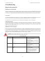
5 Troubleshooting
Diagnosis and analysing data
Identifying and resolving faults
The PVI 3000-5300 is fitted with a self-diagnostic system, which can recognise a majority of possible faults and show these on
the display. This allows the operator to rapidly identify possible problems in the solar inverter or system. Please refer to the
LCD section (4) for a thorough explanation of fault codes, modes, etc. These indicate both internal errors and external faults.
Ground Fault:
If a significant ground fault occurs in the PV array or wiring, the GFDI fuse (located on the wiring/connector panel) may be
blown. If it is, determine and repair ground fault and replace fuse with Bussmann KLKD1 (1 Amp, 600VDC).
If the GFDI detects the ground fault break, the Ground Fault LED will light and the “fault” will be displayed.
Weak Sunlight Condition:
Operation in weak sunlight, (for example early in the morning, when overcast or when snow is covering most or all of the PV
array) can cause the inverter to go through a cycle of trying to start and restart several times. This can occur if the array
reached 235V (strike voltage) but there is nearly no power available, for example in the very early morning low light or cloudy
weather. If in doubt, wait for stronger sun.
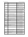
Explanations of Error Messages
In the event of a fault, the inverter will stop feeding the AC voltage to the building/utility and display the error message on the
LCD. Qualified service personnel shall do the analysis, measurement, and debug the system if needed according to the error
message in order to resume normal operation. It is recommended to analyze the fault condition(s) by referring to the table
below and then remove the fault condition(s) in order to return the inverter to normal and continue to feed AC voltage to the
utility steadily. Please contact Solectria Renewables if the same error message is persistent.
CAUTION: Certain possible solutions may expose live electrical circuits, only qualified personnel should perform
these tasks. Please use caution when measuring voltage in the inverter.
Error Message
GridNA
Error Message Table
Description
No AC voltage is detected.
Drift Fac
Islanding is detected.
VacH
The AC voltage of utility is above the upper
limit.
41
Possible Solutions
Verify AC voltage disconnect on
Verify AC circuit breaker is
on/operational
Verify and measure AC voltage present
in Inverter disconnect
Contact installing company or Solectria
Renewables
Verify AC voltage present and correct in
Inverter disconnect
Contact installing company or Solectria
Renewables
Verify setting for S201 is correct for the
grid voltage applied
Measure the AC voltage and compare to
the voltage on the inverter display
Contact Solectria Renewables for
assistance if the range needs to be
adjusted
PVI 3000/4000/5000/5300
Installation and Operation Manual
VacL
The AC voltage of mains utility is below the
lower limit.
FacH
The frequency of AC voltage of the utility is
above the upper limit.
FacL
The frequency of AC voltage of the utility is
below the lower limit.
VpvH
The DC voltage of PV array is above the upper
limit.
Imax_AC
Over current on the AC side.
InvTempMax
The internal temperature of the inverter
exceeded the safe operating limit.
Relay Open
Relay Close
VacL1 H
Relay test failed.
VacL1 L
The voltage between L1 and neutral is under
the lower limit.
VacL2 H
The voltage between L2 and neutral is over the
upper limit.
VacL2 L
The voltage between L2 and neutral is under
the lower limit.
The voltage between L1 and neutral is over the
upper limit.
42
Verify setting for S201 is correct for the
grid voltage applied
Measure the AC voltage and compare to
the voltage on the inverter display
Contact Solectria Renewables for
assistance if the range needs to be
adjusted
Measure the frequency and compare to
the frequency on the display
Contact Solectria Renewables for
assistance if the range needs to be
adjusted
Measure the frequency and compare to
the frequency on the display
Contact Solectria Renewables for
assistance if the range needs to be
adjusted
Turn off the inverter
Measure the VDC at the Inverter
disconnect if over 599VDC the solar
array needs to be inspected
Contact installing company
Do not turn on the inverter until the
condition is repaired
The inverter will continue to operate at a
lower current
If message occurs frequently contact the
installing company
If the inverter is located in direct
sunlight it may need to be shaded
The VDC input may be too high causing
increased temperature, reduce VDC
input. Contact installing company or
Solectria Renewables
Contact installing company or Solectria
Renewables
Verify setting for S201 is correct for the
grid voltage applied
Measure the AC voltage and compare to
the voltage on the inverter display
Contact Solectria Renewables for
assistance if the range needs to be
adjusted
Verify setting for S201 is correct for the
grid voltage applied
Measure the AC voltage and compare to
the voltage on the inverter display
Contact Solectria Renewables for
assistance if the range needs to be
adjusted
Verify setting for S201 is correct for the
grid voltage applied
Measure the AC voltage and compare to
the voltage on the inverter display
Contact Solectria Renewables for
assistance if the range needs to be
adjusted
Verify setting for S201 is correct for the
grid voltage applied
Measure the AC voltage and compare to
the voltage on the inverter display
Contact Solectria Renewables for
PVI 3000/4000/5000/5300
Installation and Operation Manual
MOV Fault,
AC
High voltage protection function failed on the
AC side.
MOV Fault,
DC
High voltage protection function failed on the
DC side.
GFDI
The GFDI Fuse is open or blown.
DCInjectCurH
Too much DC current injected into the AC grid
is detected.
VdcbusH
Internal DC bus voltage is above the upper
limit.
Internal
COMM
Internal communication failed.
Internal watchdog function triggered.
assistance if the range needs to be
adjusted
Verify MOV appearance is OK
Measure MOV using diode function of
DMM if shorted contact Solectria
Renewables
Verify MOV appearance is OK
Measure MOV using diode function of
DMM if shorted contact Solectria
Renewables
Use DMM to verify GFDI is open
Replace fuse with same type and rating
If fuse opens again contact installing
company to inspect and repair the array
Turn off the inverter and restart. If the
error re-occurs Contact installing
company or Solectria Renewables
Turn off the inverter and restart. If the
error re-occurs Contact installing
company or Solectria Renewables
Turn off the inverter and restart. If the
error re-occurs Contact installing
company or Solectria Renewables
Watchdog
Temp. Sensor
The DC injection current monitoring function
failed.
Offset check for grid monitoring failed.
RAM Test
The internal temperature sensor failed.
EEPROM Test
Memory failed
System Error
EEPROM test failed.
Version Error
The system failed.
CPU Delta Fac
CPU Delta Vac
CPU Delta
GFDI
CPU Delta Idc
The firmware version is not correct.
Internal measurement comparison error or
defective hardware
IpvH
Over current on the DC side
Driver Fault
Driver circuit or power device failed
CalDataError
Calibration data is out of range
CalDataLoss
Calibration data is lost.
Offset
43
Turn off the inverter and restart. If the
error re-occurs Contact installing
company or Solectria Renewables
Turn off the inverter and restart. If the
error re-occurs Contact installing
company or Solectria Renewables
Turn off the inverter and restart. If the
error re-occurs Contact installing
company or Solectria Renewables
Turn off the inverter and restart. If the
error re-occurs
Turn off the inverter and restart. If the
error re-occurs Contact installing
company or Solectria Renewables
Turn off the inverter and restart. If the
error re-occurs Contact installing
company or Solectria Renewables
Turn off the inverter and restart. If the
error re-occurs Contact installing
company or Solectria Renewables
Turn off the inverter and restart. If the
error re-occurs Contact installing
company or Solectria Renewables
Use a suitable meter for measuring the
current from the array. Verify the
current is within the limits for the
inverter. Contact the installing company
to check the array
Turn off the inverter and restart. If the
error re-occurs Contact installing
company or Solectria Renewables
Turn off the inverter and restart. If the
error re-occurs Contact installing
company or Solectria Renewables
Turn off the inverter and restart. If the
error re-occurs Contact installing
company or Solectria Renewables
PVI 3000/4000/5000/5300
Installation and Operation Manual
Ibuck Over
Internal converter over current
Converter
Error
DC/DC hardware failed.
Turn off the inverter and restart. If the
error re-occurs Contact installing
company or Solectria Renewables
Turn off the inverter and restart. If the
error re-occurs Contact installing
company or Solectria Renewables
Maintenance:
Replacing the GFDI Fuse
Remove the cap of the GFDI fuse holder to open and then replace the GFDI fuse with the same type and rating (600VDC, 1A).
Before replacement of the fuse, you must switch off the DC/AC disconnect switch and AC breaker and wait for at least 5
minutes for system to discharge.
1.
2.
3.
4.
GFDI Fuse
OPEN
Turn OFF all DC/AC disconnect switch and AC
breaker
Wait for at least 5 minutes
Exchange the fuses
Turn ON all DC/AC disconnect switch and AC
breaker
Fig 5.1 Open the cap of the GFDI fuse holder
WARNING!
For continued protection against risk of fire, replace only with the same type and ratings of fuse (600
VDC, 1 A)!
Replacing of the PV String Fuses
The inverter is shipped with four (4) 15A, 600Vdc PV string fuses for PV strings (or three for PVI 3000). However, the size of
the PV string fuse is determined by the electrical ratings of the PV module and by UL and National Electrical Code (NEC)
requirements. The minimum size of the PV string fuse is calculated using the short circuit current rating (Isc) of the PV
module. The NEC requires that the fuse be sized for a minimum of 1.56 times the Isc of the PV module used in the system and
not over the module’s fuse rating. Please be sure to consult with the PV module manufacturer for appropriate PV string fuse
rating. IN NO CASE SHALL FUSES OF LARGER THAN 15A BE USED FOR THE PV STRING FUSES.
Replacing PV Fuses
STOP!
WARNING! EXTREME SHOCK AND FIRE HAZARD!
FAILURE TO FOLLOW THE FOLLOWING PROCEDURE CAN RESULT IN SERIOUS SHOCK,
FIRE DAMAGE AND WILL VOID INVERTER WARRANTY!
44
PVI 3000/4000/5000/5300
o
o
o
o
Installation and Operation Manual
REMOVE WIRING BOX COVER
CHECK DC VOLTAGES OF ALL STRINGS USING 600V DC METER
MEASURED VOLTAGES SHOULD BE OPEN CIRCUIT VOLTAGE; IF THE
MEASURED VOLTAGE IS AT OR CLOSE TO 0.0Vdc, THEN STOP! AND DO NOT
REMOVE ANY FUSES. RECHECK YOUR WIRING TO ENSURE THERE IS NOT A
DEAD SHORT OR A STRING WITH REVERSED POLARITY.
CHECK DC CURRENT OF ALL STRINGS USING CLAMP-ON DC METER
MEASURED CURRENTS SHOULD BE AT OR VERY CLOSE TO 0.0Adc. IF THERE IS
A MEASURED CURRENT READING, THEN STOP! AND DO NOT REMOVE ANY
FUSES. RECHECK YOUR WIRING TO ENSURE THERE IS NOT A DEAD SHORT OR
A STRING WITH REVERSED POLARITY.
ONCE THE VOLTAGES AND CURRENTS ARE MEASURED AND CONFIRMED TO BE
CORRECT, REMOVE AND REPLACE THE PV STRING FUSES.
Fig 5.2 Replacement of the PV string fuses
WARNING!
PV arrays is always energized when exposed to light therefore hazardous voltage is still present on the
terminal blocks and the PV string fuse holders even the DC/AC disconnect switch is switched OFF.
Please cover the PV arrays with opaque (dark) materials during PV string fuse replacement.
!
CAUTION!
The string fuse size must not be greater than the maximum fuse size rating of the PV module provided
on the PV module manufacturer data sheet. If no maximum fuse size is indicated, please contact the
PV module manufacturer.
Factory Service
Please contact Solectria Renewables customer service for our documentation for removing and replacing inverter section
(while leaving wiring box in place).
6 Product Warranty & RMA Policy
6.1 Warranty Policy
The Solectria Renewables Warranty Policy is stated below.
Solectria Renewables Warranty Coverage:
45
PVI 3000/4000/5000/5300
Installation and Operation Manual
Solectria Renewables Limited Warranties are provided by Solectria Renewables, LLC. ("Solectria Renewables") and cover
defects in workmanship and materials.
Duration of a Solectria Renewables Warranty Period:
The warranty period is 120 months from the date of purchase of the PVI3000/4000/5000/5300 by the end user or 124 months
after the delivery date from Solectria Renewables to installer, dealer, distributor (merchant) whichever is shorter.
If Solectria Renewables repairs or replaces a product, its warranty continues for the remaining portion of the original Warranty
Period or 90 days from the date of the return shipment to the customer, whichever is greater.
All warranties are null and void if full payment for products and associated shipping are not received in full and in a timely
manner by Solectria Renewables.
Please contact Solectria Renewables Customer Service for further details on other products.
What will Solectria Renewables do?
Solectria Renewables will, at its option, repair or replace the defective product free of charge, provided that you notify
Solectria Renewables of the product defect within the Warranty Period for your product, and provided that Solectria
Renewables, through inspection, establishes the existence of such a defect and that it is covered by the Limited Warranty.
Solectria Renewables will, at its option, use new and/or reconditioned parts in performing warranty repair and building
replacement products. Solectria Renewables reserves the right to use parts or products of original or improved design in the
repair or replacement. All replaced products and all parts removed from repaired products become the property of Solectria
Renewables.
Solectria Renewables will attempt to repair the unit within a reasonable time period (there is no reimbursement for lost energy
production.)
Solectria Renewables covers both parts and labor necessary to repair the product, and return shipment to the customer via a
Solectria Renewables-selected non-expedited surface freight within the contiguous United States and Canada. Alaska and
Hawaii and the Rest of The World are excluded. Contact Solectria Renewables customer service for details on freight policy
for return shipments outside of the contiguous United States and Canada.
Obtaining Service:
If your product requires troubleshooting or warranty service, contact your merchant. If you are unable to contact your
merchant, or the merchant is unable to provide service, contact Solectria Renewables directly at the number listed on the
website in the customer service section for your product.
Direct returns may be performed according to the Solectria Renewables Return Material Authorization Policy.
In any warranty claim, dated proof of purchase must accompany the product and the product must not have been disassembled
or modified without prior written authorization by Solectria Renewables.
Proof of purchase may be in any one of the following forms:
- The dated purchase receipt from the original purchase of the product at point of sale to the end user, or
- The dated merchant invoice or purchase receipt showing original equipment manufacturer (OEM) status, or
- The dated invoice or purchase receipt showing the product exchanged under warranty.
What does the Solectria Renewables warranty not cover?
Solectria Renewables Limited Warranties do not cover normal wear and tear of the product or costs related to the removal,
installation, or troubleshooting of the customer's electrical systems. These warranties do not apply to and Solectria Renewables
will not be responsible for any defect in or damage to:
a) The product if it has been misused, neglected, improperly installed, physically damaged or altered, either internally or
externally, or damaged from improper use or use in an unsuitable environment; this includes but is not limited to damage
caused by improper removal or installation of PV string fuses, or if incorrectly rated PV string fuses are used.
b) The product if it has been subjected to fire, water, generalized corrosion, biological infestations, acts of God or input
voltage that creates operating conditions beyond the maximum or minimum limits listed in the Solectria Renewables product
specifications including high input voltage from generators and lightning strikes;
c) The product if repairs have been done to it other than by Solectria Renewables;
d) The product if it is used as a component part of a product expressly warranted by another manufacturer;
e) The product if its original identification (trademark, serial number) markings have been defaced, altered, or removed;
f) The product if it has been damaged in shipping
g) Any installation and operation beyond the scope covered by relevant safety regulations (UL1741, NEC, etc.);
46
PVI 3000/4000/5000/5300
Installation and Operation Manual
DISCLAIMER
SOLECTRIA RENEWABLES LIMITED WARRANTIES ARE THE SOLE AND EXCLUSIVE WARRANTY
PROVIDED BY SOLECTRIA RENEWABLES IN CONNECTION WITH YOUR SOLECTRIA RENEWABLES
PRODUCT AND ARE, WHERE PERMITTED BY LAW, IN LIEU OF ALL OTHER WARRANTIES,
CONDITIONS, GUARANTEES, REPRESENTATIONS, OBLIGATIONS AND LIABILITIES, EXPRESS OR
IMPLIED, STATUTORY OR OTHERWISE IN CONNECTION WITH THE PRODUCT, HOWEVER ARISING
(WHETHER BY CONTRACT, TORT, NEGLIGENCE, PRINCIPLES OF MANUFACTURER'S LIABILITY,
OPERATION OF LAW, CONDUCT, STATEMENT OR OTHERWISE), INCLUDING WITHOUT RESTRICTION
ANY IMPLIED WARRANTY OR CONDITION OF QUALITY, MERCHANTABILITY OR FITNESS FOR A
PARTICULAR PURPOSE. ANY IMPLIED WARRANTY OF MERCHANTABILITY OR FITNESS FOR A
PARTICULAR PURPOSE TO THE EXTENT REQUIRED UNDER APPLICABLE LAW TO APPLY TO THE
PRODUCT SHALL BE LIMITED IN DURATION TO THE PERIOD STIPULATED UNDER THIS LIMITED
WARRANTY.
IN NO EVENT WILL SOLECTRIA RENEWABLES, LLC, INCLUDING ITS SUPPLIERS, MANUFACTURERS,
VENDORS, SUBCONTRACTORS, DISTRIBUTORS, DEALERS AND ANY OTHER AFFILIATES BE LIABLE
FOR ANY SPECIAL, DIRECT, INDIRECT, INCIDENTAL OR CONSEQUENTIAL DAMAGES, LOSSES, COSTS
OR EXPENSES HOWEVER ARISING WHETHER IN CONTRACT OR TORT INCLUDING WITHOUT
RESTRICTION ANY ECONOMIC LOSSES OF ANY KIND, ANY LOSS OR DAMAGE TO PROPERTY, ANY
PERSONAL INJURY, ANY DAMAGE OR INJURY ARISING FROM OR AS A RESULT OF ANY USE, MISUSE
OR ABUSE, OR THE (IN-) CORRECT INSTALLATION, INTEGRATION OR OPERATION OF THE PRODUCT.
Solectria Renewables neither assumes nor authorizes any other person to assume for it any other liability in connection with
the repair or replacement or the Product.
Exclusions of the Policy:
If your product is a consumer product, federal law does not allow an exclusion of implied warranties. To the extent you are
entitled to implied warranties under federal law, to the extent permitted by applicable law they are limited to the duration of
this Limited Warranty. Some states and provinces do not allow limitations or exclusions on implied warranties or on the
duration of an implied warranty or on the limitation or exclusion of incidental or consequential damages, so the above
limitation(s) or exclusion(s) may not apply to you. This Limited Warranty gives you specific legal rights. You may have other
rights, which may vary from state to state or province to province.
WITHOUT LIMITING THE GENERALITY OF THE FOREGOING, UNLESS SPECIFICALLY AGREED TO BY
IT IN WRITING, SOLECTRIA RENEWABLES
(a) MAKES NO WARRANTY AS TO THE ACCURACY, SUFFICIENCY OR SUITABILITY OF ANY
TECHNICAL OR OTHER INFORMATION PROVIDED IN MANUALS OR OTHER DOCUMENTATION
PROVIDED BY IT IN CONNECTION WITH THE PRODUCT; AND
(b) ASSUMES NO RESPONSIBILITY OR LIABILITY FOR LOSSES, DAMAGES, COSTS OR EXPENSES,
WHETHER SPECIAL, DIRECT, INDIRECT, CONSEQUENTIAL OR INCIDENTAL, WHICH MIGHT ARISE
OUT OF THE USE OF SUCH INFORMATION.
THE USE OF ANY SUCH INFORMATION WILL BE ENTIRELY AT THE USER'S RISK.
WARNING: LIMITATIONS ON USE
Please refer to your product user manual for limitations on uses of the product. Specifically, please note that Solectria
Renewables products are not intended for use in connection with life support systems and Solectria Renewables makes no
warranty or representation in connection with any use
of the product for such purposes.
Please review our Return Merchandise Authorization Policy for returning product to Solectria Renewables.
6.2 Return Material Authorization Policy
Please review our Return Merchandise Authorization Policy below after reviewing our Solectria Renewables Warranty Policy.
Obtaining a required, Return Material Authorization:
Before returning a product directly to Solectria Renewables you must obtain a Return Material Authorization (RMA) number
and the correct factory "Ship To" address. Products must also be shipped prepaid. Product shipments will be refused and
47
PVI 3000/4000/5000/5300
Installation and Operation Manual
returned at your expense if they are unauthorized, returned without an RMA number clearly marked on the outside of the
shipping box, if they are shipped collect, or if they are shipped to the
wrong location.
Information Solectria Renewables needs when you are obtaining service:
1) The model names and serial number of your product
2) Information about the installation and use of the unit
3) Information about the failure and/or reason for the return
4) A copy of your dated proof of purchase.
Preparing the product for shipping (an RMA form will be sent to you):
1) Package the unit safely, preferably using the original box and packing materials. Please ensure that your product is shipped
fully insured in the original packaging or equivalent. This warranty will not apply where the product is damaged due to
improper packaging.
2) Include the following:
a. The RMA number supplied by Solectria Renewables, LLC clearly marked on the outside of the box
b. A return address to which the unit can be shipped. Post office boxes are not acceptable.
c. A contact telephone number where you can be reached during work hours.
d. A brief description of the problem.
Ship the unit prepaid to the address provided by your Solectria Renewables customer service representative.
Returning a product from outside of the USA or Canada:
In addition to the above, you MUST include return freight funds and are fully responsible for all documents, duties, tariffs, and
deposits.
48
PVI 3000/4000/5000/5300
Installation and Operation Manual
7 Technical Data
Technical Information and specifications – also see PVI 3000-5300
brochure for information and on the inverters. (see Appendix B for info).
Input (DC) from PV array:
Maximum open circuit voltage of PV array: 600V DC
WARNING: NEC 690-7 must be followed to calculate the maximum number of PV modules allowed for a
maximum inverter open circuit voltage (OCV) of 600V DC in extreme cold temperatures for the installation
location.
See PV string sizing chart example in Appendix C.
DC Current (A)
The open circuit voltage of PV modules depends on the cell temperature and the solar irradiation. The highest
open circuit voltage occurs when the PV modules are at the coldest temperature and in bright sun. (See the
following figure – Fig. 7.5)
8
6
at 50 deg C
4
at 20 deg C
at -20 deg C
2
0
0
10
20
30
Voltage (VDC)
Fig. 7.1 Example representative ~100W PV module voltage –
current characteristic at various cell temperatures
Because PV modules also have a reduction in voltage at high cell temperatures, you must make sure the MPP voltage of the
strings will not drop below the minimum inverter DC input voltage of 200V DC in very hot temperature conditions, including
wire losses/voltage drop.
Both the maximum open circuit voltage (OCV) when at cold extreme and minimum MPP voltage when at hot extreme can be
calculated for a PV module using its specification sheet. PV module string sizing can then be used to determine how many
modules can/should be used in a string.
49
PVI 3000/4000/5000/5300
Installation and Operation Manual
Inverter Specifications
PVI 3000
DC Input Specifications
Continuous Power @240 VAC
@208 VAC
Recommended Max. PV
@240 VAC
Array Power, STC Rating
@208 VAC
MPPT Voltage Range
Maximum Input Voltage
Strike Voltage
Maximum Input Current
Maximum Short Circuit Current
Fused Inputs
AC Output Specifications
Continuous Power @240 VAC
@208 VAC
Voltage Range @240 VAC
@208 VAC
Frequency
Continuous Current (Max.)
Output Current Protection
Max. Backfeed Current to PV
Power Factor
THD
Efficiency Peak @240 VAC
@208 VAC
CEC Efficiency @240 VAC
@208 VAC
General
Enclosure
Housing Material
Ambient Temperature Range
Cooling
Weight
Size (L x W x H)
Wire Sizes
Standards
Warranty
PVI 4000
PVI 5000
PVI 5300
3050W
2840W
3600W
4100W
3580W
4900W
5150W
4520W
6200W
5575W
4840W
6700W
3400W
4300W
5400W
5800W
200V-550 VDC
600 VDC
235 VDC
16 A
24 A
3
200V-550 VDC
600 VDC
235 VDC
20 A
24 A
4
200V-550 VDC
600 VDC
235 VDC
25 A
30 A
4
200V-550 VDC
600 VDC
235 VDC
25 A
30 A
4
2900W
2700W
211-264 VAC
183-228 VAC
60Hz
Range: 59.3-60.5Hz
3900W
3400W
211-264 VAC
183-228 VAC
60Hz
Range: 59.360.5Hz
16.5 A
20 or 25 A
0A
Utility, >99%
<3%
96.7
96.5
96
95.5
13.1 A
20 A
0A
Utility, >99%
<3%
96.7
96.4
96
95.5
Convection
50.7 lb (23 kg)
4900W
5300W
4300W
4600W
211-264 VAC
211-264 VAC
183-228 VAC
183-228 VAC
60Hz
60Hz
Range: 59.3-60.5Hz Range: 59.3-60.5Hz
20.8 A
25 or 30 A
0A
Utility, >99%
<3%
96.6
96.4
96
96.0
22.5 A
30 A
0A
Utility, >99%
<3%
96.4
96.2
96
95.5
Rainproof, NEMA 3R
Painted aluminum
-25C to +55C
Convection and fan assist
50.7 lb (23 kg)
61.7 lb (28 kg)
61.7 lb (28 kg)
28 4/5 in x 17 3/4 in x 6 3/4 in (732mm x 454mm x 175mm) 28 4/5 in x 17 3/4 in x 8 1/4 in (732mm x 454mm x 210mm)
12 to 6 AWG input and output connections
UL1741/IEEE1547, IEEE1547.1, CSA22.2#107.1, ANSI62.41.2, FCC part 15 B
10 years standard
This maximum recommended power is a nominal figure based on an array with a relatively optimal tilt angle
and orientation (south) as well as other average conditions. Array over-sizing is used because PV modules
rarely run at their STC ratings. However, if the array is oversized too much clipping of maximum power by
the inverter can occur in optimal conditions. PV module STC conditions are rarely achieved because the
cells are usually at a higher temperature when full 1-sun is available, or when cells are at STC temperatures,
the sun's intensity is often times less than 1-sun. Because STC conditions are rarely achieved, array oversizing of 10-20% achieves best overall economic trade-off with inverter and array costs. The maximum
recommended power to be connected to the inverter is very much dependent on average weather conditions,
economic optimization, tilt and of the array and orientation (for example south, or rotating array). For arrays
that are flat or nearly flat in northern location where the sun's rays are never close to being perpendicular to
the array, the array can be oversized more than these recommendations. For locations that are hazy or
cloudy for most of the year, also more array over-sizing may be appropriate. For arrays aiming at the sun or
rotating arrays that face the sun all the time, less array over-sizing may be a good choice.
50
PVI 3000/4000/5000/5300
Installation and Operation Manual
Output to AC grid connection:
The PVI 3000-5300 is designed to feed power into a standard 60Hz, 240 or 208V AC utility service or 208V AC provided
within a facility by a step down transformer (for example, from 480V AC service). As required by NEC, there must be a
dedicated 2-pole circuit breaker for the PV inverter connection. This circuit breaker (and wiring) must have a rating of 20, 25
or 30A depending on the model. The inverter is designed to work with the range of AC voltage for a 240VAC or 208V
service defined by UL1741/IEEE1547.
AC Output of PVI 3000-5300
6000
AC Output Power (W)
PVI 5300
5000
PVI 5000
4000
PVI 4000
3000
PVI 3000
PVI 3000
PVI 4000
PVI 5000
PVI 5300
2000
“strike” voltage (235VDC)
1000
0
200
250
300
350
400
450
500
DC Input Voltage (VDC)
Fig. 7.2 AC Output power of PVI 3000-5300
Fig. 7.3 Serial Number Key (description)
51
550
600
PVI 3000/4000/5000/5300
Installation and Operation Manual
Appendices
Appendix A: PVI 3000/4000/5000/5300 brochure
The brochure can also be viewed on the website: http://www.solren.com/downloads/PVI_3000-5300 kW.pdf
Appendix B: Example string sizing PVI 3000/4000/5000/5300
(Note that the chart below is only to show how string sizing charts look. Please refer to the website version for
complete and updated charts for use in all temperature zones across the country.)
Updated string sizing tables are available on the website: www.solren.com
All string sizing charts in: http://www.solren.com/products/pwreleccomp.html
Specific PVI 3000-53000 Link:
http://www.solren.com/downloads/Solectria_Renewables_String_Sizing_PVI_30005300_String_Sizing_as_of_5_21_08.pdf
Appendix C: Contact Information
Authorized Dealers and Installers – see website: www.solren.com
Specific link: http://www.solren.com/contact/dist.htm
Solectria Renewables LLC
360 Merrimack Street
Building 9
Lawrence, Massachusetts, 01843
USA
Tel: 978.683-9700
Fax: 978.683-9702
Email: [email protected]
Website: www.solren.com
52
PVI
P 3000/40000/5000/5300
Installlation and Opperation Manuual
Appendix
A
D – Negative Grrounding and
d Positive Groounding Optiion
Connection
C
n of the DC wiring
The wirinng box of the PVI 3000-5300 inverter is designed withh a pair of DC
C terminal blocks which suppport up to fouur (4)
independent PV strings to be connectedd in parallel inn the wiring boox and then feeed into the invverter. The PV
VI 4000, 50000, and
V string fusess for the PV sttrings. The PV
VI 3000 is shippped with threee (3)
5300 are shippped with up to four (4) 155A, 600Vdc PV
15A, 600Vddc PV string fuuses, and therrefore, the fouurth pair of terrminals (from left as shownn in figure D1 are not be ussed to
connect to a PV string. However, thee size of the PV string fusse shall be deetermined by the electrical ratings of thhe PV
module and by UL and Naational Electriical Code (NE
EC) requiremeents. Please reefer to the secttion 5 for the replacement of
o the
PV string fusses.
There aree two (2) term
minals, labeledd “Ungroundeed (+)” and “G
Grounded (-)”,, per PV string
g located in thhe wiring boxx used
for the DC cconnections. The
T DC equippment ground wire shall bee connected to
o the screw off the ground bbar labeled
the wiring boox of the inveerter. All the sccrews shall bee tightened wiith a torque off 15.6 Lb-in (11.7Nm).
1
Negative ground
1
Positvie ground
Fig
F D1
in
PVI 40000 supports only four (44) PV stringg fuses (show
wn), the PV
VI 3000 suppports only three
t
(3) PV sttring fuses (not
(
shown)).
ve ground forr PV strings connections.
c
T JP14 andd JP15 jumperrs are
The
The inveerters supportss both negativve and positiv
used for the settings of thee negative andd positive grouunding.
Connection
C
n of the DC wiring forr Negative Grounded
G
Systems
When thhe inverter is shipped
s
with the negative ground setting, it is set as shown in thee figure D2. T
The JP14 and JP15
jumpers are placed on thee lower positions to set to the
t negative ground
g
and th
he red Vdc wiire is connecteed to Ungrounnded,
DCIN+ term
minal, the black
k Vdc wire is connected to Grounded, DCIND
terminaal. In this casee the positive polarity of thhe DC
input from thhe PV string shall be conneected to Ungrrounded (+) teerminal and thhe negative po
olarity of the DC input from
m the
PV string shall be connectted to Ungrouunded (-) termiinal as shownn in the figure D3.
53
PVI 3000/4000/50000/5300
Installatio
on and Operattion Manual
JP15
JP15
JP14
1
Positvie ground
1
Negative ground
JP14
1
Negative ground
1
Positvie ground
Blaack
wire
cted
to
Black
wireconnec
connec
cted to
DCIN--
DCINounded,
Red wire
e connected toGro
connecte
DCIN+ ed to
Redd wire
Unngrounded, DCIIN+
Fig D22
Neggative Grouund Setting and Vdc wiires connecttions
connect to PV+
connect to
o PV-
!
·
·
·
1
Negative ground
GROUNDED
D
CONDUCTO
OR
UNGROUNDED
CONDUCTOR
Fig D3
1
Positvie ground
UNGROUNDED
D
CONDUCTOR
UNDED
GROU
COND
DUCTOR
D terminaal blocks forr DC conneections in Negative
DC
Ne
Gro
ound System
ms
UTION!
CAU
Polaarities of eacch DC input from a PV string shalll be correctly
y connected to the “Unggrounded (+))”
(positive) and “G
Grounded (–))” (negative) terminals off a pair respectively. Th
he DC voltagee must be less
than
n 600V in anyy condition.
The
T “Ungrounnded (+)” wiire of the DC
C input shall be connectedd to the term
minal labeled “Ungroundedd (+)” and thhe
“Grounded
“
(-))” wire of the DC
D input shalll be connecteed to the terminal labeled “G
Grounded (-)”.
Avoid
A
using w
wire nuts to jo
oin any wires together or too make any connections
c
inn the PV systeem. Wire nutss are a frequen
nt
cause
c
of unreliiable connectiions, resistive connections, and ground faaults.
.
Connect
C
the eqquipment grouund cable to thhe screw of th
he ground bar labeled
Tighten
T
the screws with a toorque of 15.6 Lb-in (1.7Nm
m).
54
PVI 3000/4000/5000/5300
Installation and Operation Manual
Connection of the DC wiring for Positive Grounded Systems
The PVI 3000-5300 inverter also supports positive ground for some applications. This option should be ordered from the
factory if positive grounding is desired. If ordered as positively grounded with the “P” suffix on the part number, it will
come with a label on the front stating that it is a Positive Grounded unit and the PV+ and PV- will be labeled for positively
grounded, etc. The connections to the array follow the same instructions as above for hook up.
If any inverter is ordered as negatively grounded, it can be “converted” to positively grounded following these
instructions:
1.) Open the wiring box (lower unit with AC/DC disconnect in the center) and remove the inverter cover (upper unit)
2.) As shown in the figure D4, below, the JP14 and JP15 jumpers need to be placed at the higher positions to set to
positive grounding.
3.) The red DC wire (that connects the inverter board to the wiring box below) needs to be connected to Grounded,
DCIN- (labeled “Ungrounded (+)“) terminal on the wiring box PCB and the black DC wire (that connects the
inverter board to the wiring box below) needs to be connected to Ungrounded, DCIN+ terminal on the wiring box
PCB.
4.) Add permanent weatherproof labels over the Ungrounded (+) and Grounded (-) labels below the green terminal
blocks. The left terminal block must be labeled “Ungrounded (-)“ and the right terminal block must be labeled
“Grounded (+)”. Optional: add “Warning, Positively Grounded Unit” label to outside of unit at bottom right corner
of wiring box. (a label kit is available from Solectria if requested).
In this case the installer shall connect the positive polarity of the DC input from the PV string(s) to the original Grounded
(-) terminal(s) which are now labeled “Ungrounded (-)”and the negative polarity of the DC input from the PV string(s) shall
be connected to original Ungrounded (+) terminal(s) now labeled Grounded (-) as shown in the figure D5.
JP15
JP15
JP14
1
Positvie ground
1
Negative ground
JP14
Negative ground
1
Positvie ground
1
Redwire
wireconnected
connectedtoto
Red
Grounded,
DCINDCINBlack
wire
connected
to
Black wire connected to
DCIN+
Ungrounded,
DCIN+
Fig D4
Positive Ground Setting and Vdc wires connections
55
PVI 3000/4000/50000/5300
Installatio
on and Operattion Manual
co
onnect to PV+
+
Negative ground
1
Positvie ground
1
UNGROUNDED
CONDUCTOR
F
Fig D5
!
·
·
·
GROUNDED
CONDUCTOR
DC termiinal blocks for
f DC cable connectioon in Positiive Ground
CAU
UTION!
The Positive Pollarities of thee DC input from a PV strings
s
shall be correctlyy connected to
t the original
“Grounded (-)” (negative) teerminals (re--labeled “Groounded (+)”)) and the Neegative Polarrity of the DC
ut from a PV string shall be
b connected to the original “Ungrounded (+)” (possitive) termin
nals (re-labeleed
inpu
“Un
ngrounded (-)“). The DC voltage
v
must be
b less than 600V
6
in all co
onditions.
Avoid
A
using w
wire nuts to jo
oin any wires together or too make any connections
c
inn the PV systeem. Wire nutss are a frequen
nt
cause
c
of unreliiable connectiions, resistive connections, and ground faaults.
Connect the equipmen
nt ground wiree to the screw of the groundd bar labeled .
Tighten tthe screws witth a torque of 15.6 lb-in (1.7
7Nm).
!
CAU
UTION!
PV arrays
a
are en
nergized when
n exposed to light.
l
Use safe working practices when
n working on
n PV arrays.
WAR
RNING!
Rou
ute the DC coonnection cab
bles to the in
nverters awayy from any possible
p
hazards that coulld damage th
he
cablles.
WAR
RNING!
Hazaardous voltagge is still preesent on the device
d
after iis it disconneected from all
a PV DC inp
puts. Allow 5
minu
utes for the in
nverter to disccharge the en
nergy compleetely.
·
Up
U to four (4) independent PV strings (44 pairs) can bee connected too the inverter as
a shown in th
he figure 3C. The PV string
gs
are
a connected in parallel inn the wiring boox. Thereforee, these four (4)
( PV stringss shall be the same in capaacity, especiallly
each
e
total strinng voltage.
PV+
N
L2
L1
PV-
Fig D6
D
P terminaal connectioon
PV56
PVI 3000/4000/5000/5300
Installation and Operation Manual
Appendix E Weatherproof Shield for wind-driven snow and rain conditions
The weather proof shield is to be installed on inverters when the chance of rain, snow or severe weather may occur. Examples
of installations needing the shields are:
Units installed on trackers.
Units installed outdoors, fully exposed to elements and in climates where severe weather can occur.
Please follow the installation steps below:
Step 1: Remove the eight(8) screws used to fasten the inverter cover. It is not necessary to remove the inverter cover. (Notice:
Don’t throw these eight(8) screws away. The screws will be used to fasten the shields later.)
Fig 6.1 Step 1: Remove the screw of the inverter cover
Step 2: Install the shields on the sides of the inverter and cover the air vents. The larger shield is used for the upper vent and
the small on is for the lower.
Fig 6.2 Step 2: Secure the shields on the sides of the inverter.
57
PVI 3000/4000/5000/5300
Installation and Operation Manual
Appendix F. PVI 3000‐5300 PV Inverter Fault Report Form Basic information Model (i.e. “PVI 3000”) Serial number Purchased from Purchased date Y/ M/ Installation information Type of installation Residential Commercial Installation date Y/ M/ First operation date Y/ M/ AC wire size and length ____ AWG wire size feet length of wire DC wire size and length ____ AWG wire size feet length of wire PV panel mount Roof Pole Ground Solar tracker Yes No PV strings Output power Normal voltage range Vdc Peak open circuit voltage Vdc Normal current rating Adc maximum current rating Adc Number of panels Number of series/parallel S/ P PV panel brand & model Fault/error information (please write down exact words that appear on the LCD) Fault message 1 on LCD D D D Fault message 2 on LCD Fault message 3 on LCD Fault message 4 on LCD Fault message 5 on LCD Fault message 6 on LCD ‐Does this failure happen regularly or intermittently? ‐Can you reproduce the failure? ‐How much energy has been produced thus far? (kWh) Description of problem Form filled out by Date
58
PVI 3000/4000/5000/5300
Installation and Operation Manual
Appendix G – UL1741/IEEE1547 Listing Letter
59