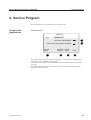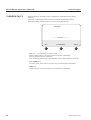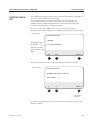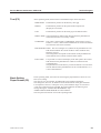
1
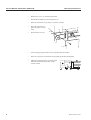
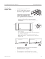
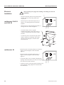
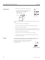
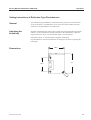
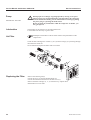
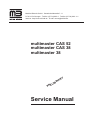
Mathias Bäuerle GmbH · Gewerbehallestraße 7-11
D-78112 St.Georgen · Telefon (07724) 882-0 · Telefax (07724) 882-111
Internet: http://www.mbfold.de · E-mail: [email protected]
multimaster CAS 52
multimaster CAS 38
multimaster 38
Y
R
A
IN
LIM
E
PR
Service Manual
Service Manual multimaster CAS 52/38
CONTENTS
1. MOUNTING INSTRUCTIONS
5
Flat Pile Feeder
Fold Unit with Register Table
Connecting Components
Air Feeder PBA
Fold Unit with Register Table
Connecting Components
Adjusting the Register Table
Transfer Bridge
Second Fold Unit
Fanned Delivery AM 52
Electrical Installation
5
5
5
7
7
7
9
10
10
11
12
2. OPERATION
Checking the Line Voltage
Flat Pile Feeder
Compressor
Pumps
Setting Instructions for Paper Thickness Sensor
Setting Instructions of Reflection-Type Photodetector
Speed Controller
3. SERVICE INSTRUCTIONS
Cleaning and Maintenance
Cleaning the Fold Rollers
Basic Setting of Fold Rollers
Replacing the Fold Rollers
Basic Setting of Roller Potentiometers
Automatic Fold Plates
Gate Fold Plate
Basic Setting of Segment Fold Plates
Squareness of the Register Table
Replacing the Flat Belt
Exchanging the One-Way Drive Roller
Delivery
Pump (Manufacturer: Rietschle)
Pump (Manufacturer: Becker)
4. SERVICE PROGRAM
Graphic Arts Applications
Systems Configuration
13
13
13
14
14
15
17
18
19
19
20
21
22
24
25
30
34
34
37
38
39
40
42
43
43
49
The title, copyright and all other proprietary rights in this document are vested
in Mathias Bäuerle GmbH and no part of it may be reproduced in any form
without the written permission of Mathias Bäuerle GmbH.
Mathias Bäuerle GmbH
3
Service Manual multimaster CAS 52/38
4
Mathias Bäuerle GmbH
Service Manual multimaster CAS 52/38
Mounting Instructions
1. MOUNTING INSTRUCTIONS
Flat Pile Feeder
•
Unpack the flat pile feeder.
Adjust the height as follows:
-
Fold Unit with
Register Table
•
9 cm
Unpack the fold unit.
When using a knife to cut open the packaging, be careful not to damage
parts of the machine!
!
•
Loosen the hexhead nuts (24 mm
wrench).
Set the height to 9 cm by means of
an 8 mm Allen key.
Level the feeder, using a spirit
level.
Remove both side covers of the
register table (1).
1
6
Remove screws (2) and (3).
Remove the connecting screws between
register table and flat pile feeder (4).
2
5
3 4
Unscrew the plug of the paper thickness
measuring device (5) and pull it off (may
otherwise be damaged!).
Pull out the studs at the register table (6).
Connecting
Components
•
Set the fold unit to the same height as the flat pile feeder and level it using a
spirit level.
•
Move the fold unit up to the flat pile feeder with a jacklift.
Observe the following:
-
The green round belt at the rear of the flat pile feeder must be guided
through the elongated hole in the register table.
Slide the register table exactly in the mating part of the flat pile feeder.
(The holes for the mounting screws must line up exactly with the threads).
Check the correct height adjustment of register table and flat pile feeder.
Check for parallelism, i.e. the gap between register table and flat pile feeder
must be the same on the operator side and on the opposite side.
!
•
Do not bend or squeeze hoses, cables or sheet-metal parts!
Insert the connecting screws between register table and flat pile table (4) and
tighten them.
Re-insert the stud at the register table (6).
Insert the plug of the paper thickness measuring device (5) and tighten it.
Mathias Bäuerle GmbH
5
Service Manual multimaster CAS 52/38
Mounting Instructions
•
Remove the cover (1) of the flat pile feeder.
•
Pull off the round belt (2) from the pulley (3).
•
Place the round belt (4) on pulleys (5) and (3) (inside).
•
Place the round belt (2)
again on pulley (3) (outside).
•
2
4
Re-attach the cover (1).
3
5
1
6
•
Insert the plug (register table) in the receptacle (flat pile feeder).
•
Place the compressor on the floor between flat pile feeder and fold unit.
•
Mount the connecting bars (6) between the
fold unit and the flat pile feeder, using a
24 mm wrench.
6
Mathias Bäuerle GmbH
Service Manual multimaster CAS 52/38
Mounting Instructions
6
Air Feeder PBA
• Unpack the air feeder (PBA) and remove both
covers of the stand (1).
Adjust the height as follows:
- Loosen the two locknuts (2) on the feet (3) by
means of a 24 mm key.
- Set all 4 feet to a height of 9 cm, using a 8 mm
Allen key.
- Level the feeder with a spirit level.
Readjust the position of the feet, if necessary.
- Secure all feet by tightening the locknuts.
4
5
7
6
7
1
2
9 cm
3
- Remove setting knobs (4) and (5) with a 3-mm key.
- Remove both side covers (6) by loosening Allen screws (7) with a 4 mm key.
Fold Unit with
Register Table
• Unpack the fold unit.
When using a knife to cut open the packaging, be careful not to damage
parts of the machine!
!
-
Remove the Allen screws (8) left and
right.
-
Then remove both side covers (9) of
the register table.
-
Remove the connecting screws (10)
between air feeder PBA and register
table.
9
10
8
• Set the fold unit to the same height as
the air feeder and level it using a
spirit level.
Connecting
Components
• Move the fold unit up to the air feeder with a jacklift.
• Slide the fold unit with register table over the connecting bracket of the
air feeder.
!
Do not bend or squeeze hoses, cables or sheet-metal parts!
The fold unit with register table is in its correct position when the holes of the
connecting brackets of the air feeder are lined up with the holes of the register table.
• Connect the register table to the air feeder with
11
attaching screws (11), using a 6-mm key.
• Place the V-belt 6x450 (12) on the pulleys of
12
register table and air feeder.
Mathias Bäuerle GmbH
7
Service Manual multimaster CAS 52/38
Mounting Instructions
• Connect the plug-type connector for the reflection-type photodetector and the
control valve with the matching counterparts at the register table.
• Re-attach all side covers of register table and
air feeder (1).
• Mount the setting knobs for the adjustment of
the vacuum plenum (2) and for the air (3).
3
2
1
• Re-attach the covers (4).
4
8
Mathias Bäuerle GmbH
Service Manual multimaster CAS 52/38
•
Adjusting the
Register Table
Mounting Instructions
Set the infeed angle to the zero position (1)
by turning the knurled screw (2).
3
1
•
Slide an A2 sheet that is known to be exactly
square between the ball cage and the alignment belt up to the alignment rail.
•
Transport the sheet along the whole length of
the register table by turning the handwheel at
2
the fold unit. Stop when the leading edge of
the sheet reaches the infeed guide (3) of the fold unit.
Check the gap between sheet and infeed guide for parallelism.
If there is a discrepancy, adjust parallelism as follows:
-
Loosen the securing knob (4) of the handwheel by turning it
counter-clockwise.
Loosen both Allen screws (2.5 mm Allen key) on the sprocket (5).
5
4
3
6
7
-
Mathias Bäuerle GmbH
7
Hold the spindle (6).
Turn the handwheel (7) somewhat to the left or right, thus changing the
basic setting of the alignment rail.
Turning clockwise: The alignment rail moves in direction of the
operator side
Turning counter-clockwise: The alignment rail moves in direction of
the opposite side.
•
Check parallelism by introducing a sample sheet as described above.
Repeat the adjusting process, if necessary.
•
Tighten both Allen screws on the sprocket (5).
•
Secure the handwheel by turning the securing knob (4) clockwise.
•
Re-attach the side covers of the register table, using a 4 mm Allen key.
9
Service Manual multimaster CAS 52/38
Transfer Bridge
Mounting Instructions
When using a second fold unit, a transfer bridge must be attached at the exit side of the
first fold unit. This bridge ensures a secure transfer of the sheet onto the roller table.
•
Connect the transfer bridge (1) to the
delivery section of the first fold unit
and secure it with two hexhead screws,
using a 13 mm wrench.
1
•
Place two drive belts (2) on the pulleys.
2
Second Fold Unit
•
Unpack the second fold unit with roller table.
!
When using a knife to cut open the packaging, be careful not to damage
parts of the machine!
•
Set the second fold unit to the same height as the roller table and level it using
a spirit level.
•
Place the second fold unit with the roller table next to the first fold unit.
•
Set the adjusting plates (3) on both sides of the transfer
bridge in such a way that the belts do not touch the
roller table.
3
•
10
Plug the connecting cable of the second fold
unit into the socket (4) of the first fold unit.
4
Mathias Bäuerle GmbH
Service Manual multimaster CAS 52/38
Fanned Delivery
AM 52
•
Unpack the fanned delivery.
When using a knife to cut open the packaging, be careful not to damage
parts of the machine!
!
•
Place the fanned delivery next to the first
or second fold unit.
•
Proceed as follows to set the transfer height:
•
Mounting Instructions
-
Loosen the securing knob (1) by turning
it counter-clockwise.
-
Lift or lower the delivery table.
-
Secure the knob (1) by turning it
clockwise.
1
Plug the connecting cable of the delivery
into the socket (2) of the first or second
fold unit.
1st FU
2
2nd FU
Mathias Bäuerle GmbH
11
Service Manual multimaster CAS 52/38
Electrical
Installation
!
Mounting Instructions
Always pull the power plug before making or breaking any electrical
installation!
1
multimaster CAS 52
and CAS 38
-
Plug the connecting cable of the operator panel
into the socket (1) in the rear panel of the
control box.
-
Route the power cord of the compressor (2)
approx. 30 cm through the strain relief and
tighten it.
-
Route the power cord of the flat pile feeder (3)
through the strain relief and tighten it.
-
Loosen the safety screw (4) against
unauthorized opening of the control box (5)
so that you can pull the control box towards
the front.
-
Connect the power cord of the flat pile feeder
and the compressor according to the wiring
diagram (wiring diagram is located inside
5
the control box).
2
3
4
multimaster 38
• Route the power cord of the pump for vacuum (6)
approx. 30 cm through the strain relief and
tighten it.
• Route the power cord of the pump for air (7)
approx. 30 cm through the strain relief and
tighten it.
• Loosen the safety screw (4) against unauthorized
opening of the control box (5) so that you can pull
the control box towards the front.
• Connect the power cord of the pump according to the
6
7
wiring diagram (wiring diagram is located inside
the control box).
12
Mathias Bäuerle GmbH
Service Manual multimaster CAS 52/38
Operation
2. OPERATION
Checking the
Line Voltage
Check the three-phase socket before switching on the machine for the first time.
400V~
400V~
400V~
S
R
230V~
230V~
T
230V~
N
0V
When making or breaking any electrical connection, always first turn off
the main switch or the safety switch on the folder!
Non-compliance may cause damage to electronic components!
!
• Turn off the main switch at the first fold unit.
• Insert the power plug into the socket.
• Turn on the main switch.
Flat Pile Feeder
•
Check the sense of rotation of the drive motor of the flat pile
feeder as follows:
1
Push button (1) on the operator panel of the flat pile feeder.
The pile table should move down.
!
If the pile table moves upwards after pushing the
"down" button (1), turn off the machine immediately
by pressing the main switch! The limit switches are
inactive and considerable damage may occur!
To change direction of the motor, proceed as follows:
Mathias Bäuerle GmbH
•
Turn off the machine by pressing the main switch and pull the power plug.
•
Open the control box of the fold unit.
•
Switch two of the three black wires of the power cable of the flat pile feeder at the
terminal block. By doing this, the sense of rotation of the drive motor is reversed.
•
Close the control box, insert the power plug.
•
Turn on main switch. Check the drive motor of the flat pile feeder for correct
function.
13
Service Manual multimaster CAS 52/38
Compressor
•
Operation
Check the sense of rotation of the compressor motor.
-
Switch on the compressor by pressing button (1).
Check the air flow at the hose fittings.
Single hose fitting:
vacuum
Double hose fitting: air
vacuum
air
5
5
5
1
If air and vacuum are reversed, the sense of rotation of the compressor motor must be
changed.
Pumps
•
Turn off the compressor by pressing button (1).
•
Turn off the machine by pressing the main switch and pull the power plug.
•
Open the control box of the fold unit.
•
Switch two of the three black wires of the power cable of the compressor at the
terminal block. By doing this, the sense of rotation of the compressor is reversed.
•
Close the control box, plug in the power plug.
•
Turn on the main switch. Check the compressor for correct function.
•
Slide the vacuum and air hoses over the hose fittings of the compressor and
secure them with hose clamps.
The pumps are connected single phase to the corresponding terminals in the control
box of the fold unit. Checking the sense of rotation is therefore not necessary.
If necessary, the intensity of vacuum and air can be adjusted
at the pump by sliding the bypass ring (2) up and down
over the bleeder hole.
2
14
Mathias Bäuerle GmbH
Service Manual multimaster CAS 52/38
Operation
Setting Instructions for Paper Thickness Sensor (CAS 52 and CAS 38 only)
Installation
The paper thickness sensor is listed as a complete unit together with the photo sensor
for sheet recognition under part-no 4.006.478. It is attached to the register table with
an Allen screw (1) M5x30, using a 4 mm key. The basic adjustment must be made
after each installation or whenever the value without paper shown in the display varies
considerably from the zero point. Measuring paper thicknesses above 0.25 mm should
be avoided as it may lead to erroneous interpretations in the program for calculating
the roller gap.
Basic Setting of the
Measuring Roller
Loosen Allen screws (2) and (3) by means of a 3 mm key so that the setting plate (4)
with setting screw (5) can be moved. Turn the setting screw (5) by means of a 3 mm
key to separate the upper measuring roller (6) from the lower one (7).
Switch on the fold roller drive. Adjust the upper measuring roller (6) until the upper
roller touches the lower roller (7) and the upper roller starts to turn.
Introduce a strip of paper between the upper and the lower roller.
There should be a slight drag on the paper. Secure the setting plate (4) by means of
screws (2) and (3), using a 3 mm Allen key.
9
10
11
5
4
2
3
6
8
Mathias Bäuerle GmbH
1
7
15
Service Manual multimaster CAS 52/38
Setting of the Zero
Point
Operation
• Loosen screws (8) and (9) with a 2 mm Allen key so bracket (10) may be moved by
means of the setting screw (11), using a 2.5 mm Allen key.
• Press key F12 on the operator panel.
Select the setting PAPER SENSOR by pressing key F6.
The display shows: BASIC SETTING ZERO POINT PAPER SENSOR.
• Set the value shown in the display to 0.00 by turning the setting screw (11) with a
2.5 mm key.
• Secure the bracket by tightening Allen screws (8) and (9).
When tightening the Allen screws, the value set may shift to + or -.
The deviation from zero has to be taken into account when repeating
the setting.
Check
• Switch on the fold roller drive to check the correct function.
• Introduce a paper strip between the measuring rollers while observing the number in
the display.
• Remove the paper strip, double it and introduce it again between the measuring
rollers. The value shown in the display must also double.
After removing the paper strip the numbers must again be identical with the
original value. If this is not the case, repeat the complete setting process.
Also check whether the mechanical components of the paper thickness sensor
are tight.
16
Mathias Bäuerle GmbH
Service Manual multimaster CAS 52/38
Operation
Setting Instructions of Reflection-Type Photodetector
General
The reflection-type photodetectors which monitor the paper travel in the fold units
are set at the factory. If malfunctions occur, always check first whether the input
sensitivity of the photodetector is still the same.
Adjusting the
Sensitivity
Introduce a dull black (both sides) sheet of paper between the photodetector and the
reflector. At the potentiometer located on the face of the photodetector, adjust the
input sensitivity in such a way that the black paper is just recognized.
Functional control: A red LED signals recognition of the paper.
For photodetectors with inverted function, the LED goes out when recognizing the
black paper.
28.6
Dimensions
24.5
Mathias Bäuerle GmbH
37
17
Service Manual multimaster CAS 52/38
Speed Controller
Operation
The information refers to the speed controller of the type EVF 8202-E, manufactured
by Lenze GmbH & Co KG.
Defective fuses may only be replaced with the recommended type of fuse.
There are no other fuses installed in the machine.
General
!
The speed controller retains voltage for up to 3 minutes after the machine
has been switched off!
The plug-in type terminals may only be inserted or removed with power off.
Operating
Conditions
When the machine is in operation, the operating
condition of the speed controller is indicated by
means of two LEDs (1) at the front panel of the
speed controller.
1
Displays
LED green
LED red
Operating condition
on
off
Speed controller enabled
on
on
Power supply off
flashing
off
Speed controller off
off
flashing (1.0 sec. pulse)
Error
off
flashing (0.4 sec. pulse)
Low voltage
off
off
Programming status
LED Display
Cause
Remedy
Green LED flashing
Controller blocked via
terminal 28
Check connections and
switch relay according to
wiring diagram
Red LED flashing
(0.4 sec. pulse)
Input voltage below
190V
Check input voltage
Red LED flashing
(1 sec. pulse)
Ground or neutral conductor defective. Speed
controller defective.
Re-establish connection
or replace speed controller (part no. 1.030.430)
LED's are dark
Programming mode still
on or no line voltage
applied
Turn off programming
mode. Check connections
according to wiring
diagram
Error Display
18
Mathias Bäuerle GmbH
Service Manual multimaster CAS 52/38
Service Instructions
3. SERVICE INSTRUCTIONS
Cleaning and
Maintenance
Minimum
Requirements
Cleaning and maintenance are vital for keeping a machine in perfect operating
condition for a long period of time.
For this reason cleaning and maintenance work should be carried out at regular
intervals. The maintenance intervals depend on the workload.
• Cleaning:
The operators should clean all fixed and moving parts from paper- or powder dust
once a week. For cleaning purposes, MB offers a special cleaning fluid.
!
Solvents such as Aceton, Toluol must not be used!
• Maintenance:
A service technician should conduct a maintenance service twice per year.
This maintenance should comprise the following jobs:
-
Mathias Bäuerle GmbH
Check the proper function of air- and vacuum controls
Clean the separating head
Check suction cups for wear; replace, if necessary
Check that moving parts move freely
Check all safety switches for proper function
Check whether chains are damaged
Check drive elements for premature wear
Check movable parts of the fold plates incl. deflector for free movement
Clean air filter of the compressor
Clean fold rollers
Check roller adjustment; re-adjust, if necessary
Check software version
19
Service Manual multimaster CAS 52/38
Cleaning the
Fold Rollers
Service Instructions
• Via the operator panel, set all fold plate stops to 262 mm.
• Turn off the main switch.
• Pull the plugs of the fold plates and remove the fold plates.
!
Place the fold plates on a table or stand them on their sides, NEVER
on the deflector!
• Turn on the folder, choosing the lowest motor speed.
• Dampen the rollers with a special roller cleaning solution.
!
Do not use solvents such as Aceton, Toluol, etc.!
• Remove dirt from the fold rollers with a soft cloth shaped into a ball.
!
Exercise caution when the machine is running!
Serious injury may result!
• Repeat the cleaning process several times, if necessary, if there is a thick layer of
deposits on the fold rollers.
• Turn off the main switch.
• Check the fold plates for damages and clean them, if necessary.
• Grease all moving parts with Molykote grease (white).
• Re-install the fold plates.
20
Mathias Bäuerle GmbH
Service Manual multimaster CAS 52/38
Basic Setting of
Fold Rollers
Service Instructions
Proper roller setting is essential for precise folding and while the pressure itself plays
an important role, parallelism between the adjoining rollers make the difference when
it comes to accuracy.
The basic setting of the fold rollers should be checked in the course of each service
inspection resp. after each replacement of the rollers. Proceed as follows:
• Turn off power.
1
• Set all setting knobs (1) left and right to
basic position (0-position).
• Pull the safety cover (2) from the handwheel,
unscrew the Allen screw (5 mm key) and
remove the handwheel.
• Remove the covers (3) on both sides of the
fold unit. Temporarily replace the handwheel
again.
• Remove the plug from each fold plate.
3
2
Loosen the locking knobs and remove
all fold plates.
• Use a strip of 30 GSM paper (4) to check the
pressure of the top roller pair (5).
While turning the handwheel, run the test strip
across the entire width of the rollers.
The strip should not break.
If it does, or if the rollers are out of parallel,
adjust by loosening the lock screw (6) with a
5 mm key on the appropriate roller mounting arm.
5
4
Turn the hexhead adjusting screw (7) until the
test strip shows even pressure across the entire
width of the rollers without breaking.
Test this setting by opening the setting knob (1)
to 0.05 mm (5 divisions).
After the setting is done, tighten the lock screw
(6) on each roller mounting arm.
7
6
• Set the remaining rollers the same way. Also test
and adjust, if necessary, the ejector roller.
• Replace the fold plates in their proper positions, 2 and 4 on the bottom, 1 and 3
on top. Reconnect the plugs.
• Remove the handwheel and replace the covers (3).
Attach the handwheel (2).
Mathias Bäuerle GmbH
21
Service Manual multimaster CAS 52/38
Replacing the
Fold Rollers
Removal
Service Instructions
Fold rollers are subject to wear, the degree of which is determined by the material and
the type of paper that is folded. They should be replaced when they show damage that
impairs their proper function resp. when high wear makes a replacement inevitable.
The degree of wear is determined in the course of the basic setting of the fold rollers
(0-position of all setting knobs).
The even pressure of the fold rollers is checked by means of a paper strip (see "Basic
Setting of fold Rollers").
The handwheel as well as the left and right side plates of the fold unit are removed
and all the setting knobs are in their basic position (0-position).
Always remove the fold rollers from the operator side of the fold unit.
Proceed as follows:
• Mark the routing of the roller drive belts (1).
6
2
• On both sides, number all levers (2) in a
continuous sequence and mark the position of
the gear (3) with respect to the setting plate (4).
This mark makes it easier to find the 0-position
of the gear and the setting knob during re-assembly.
1
3
4
• Loosen the hexhead nuts (5) on both sides with
a 13 mm open-end wrench and remove them
together with the washers from the fold rollers.
• On both sides, unhook the plates with the
springs for the belt tension.
Remove the roller drive belts (1), round
belt resp. V-belt (6) from the pulleys.
7
• Pull off the pulleys on both sides.
Watch for the woodruff keys (7) on the
fold rollers.
5
• Remove the setting knobs with hexhead
shafts (8) from the frame by pulling them
upwards. Before doing this, pry off the
white position indicator with a screwdriver.
• Use a cable tie loop to unhook all extension
springs (9) at the levers and remove the
C-clips from the locating studs.
22
8
9
Mathias Bäuerle GmbH
Service Manual multimaster CAS 52/38
Service Instructions
• Remove the lever for the upper roller. For this,
1
loosen the Allen screw (1) with a 5 mm key.
Watch for the washers on the dowel pin and
the Allen screw.
• Pull all levers from the fold rollers.
• Remove all fold rollers, starting from the top.
Make sure that the woodruff keys do not fall
into the fold unit.
Replacement
• Install the new fold rollers.
When using rubber-steel combination rollers, make sure that the PE-rings
of one roller are directly opposite the knurled steel surface of the other
roller.
• Before replacing the parts in reverse order, slightly
grease the mounting pins (2) of the levers.
The surface of all pulleys and deflector rollers
as well as the drive belts must be free of grease.
Clean them, if necessary, or install new parts.
2
• Before replacing the belts, check the roller
assembly for easy movement.
Make the basic setting of the fold rollers.
Mathias Bäuerle GmbH
23
Service Manual multimaster CAS 52/38
Service Instructions
Basic Setting of the Roller Potentiometers R10 to R21
Each setting knob from no. 1 to no. 5 is associated with a certain pair of fold rollers,
whereas setting knob no. 6 is associated with the slitter/delivery shafts.
The gap between the fold rollers or delivery shafts with respect to each other are transformed into an electrical voltage value by the potentiometers. These voltage values are
recognized by the microcomputer system and shown as the actual value on the display.
In the basic setting of the fold rollers and delivery shafts, with all the scales of the
setting knobs pointing to "0", the actual value of the roller gaps on the display must
show "0.00".
Adjustment of the basic setting for a roller potentiometer is needed when:
a)
b)
the actual value on the display shows a plus- or minus value instead of "0.00"
with the setting knobs pointing to "0".
a defective potentiometer was replaced by a new one.
Proceed as follows for setting the basic position of a roller potentiometer:
The associated fold rollers or delivery shafts must be in their basic positions.
The scale of the setting knobs must be in the 0-position.
To a) Loosen the Allen screw (1) at the upper collar on
the threaded rod of the adjustment plate by means
of a 2 mm key. At the same time, push the potentiometer (2) slightly upwards and hold it there.
Turn the second knurled collar (3) at the potentiometer shaft until "0" is shown as actual value on
the display.
Secure the zero position of the roller potentiometer
by tightening the Allen screw (1).
Turn the associated setting knob several times to the
0-position and check whether the zero reading at
the knob agrees with the 0.00 reading on the display.
If not, repeat the procedure.
3
1
To b) Turn off the machine at the main switch.
Use a soldering iron to separate the electrical wires
of the defective potentiometer from the connections.
Before doing this, mark the connections in order to
prevent errors.
Loosen the Allen screw (1) on the upper collar by
means of a 2 mm key and remove the defective
potentiometer.
Solder the electrical wires to the new potentiometer with the help of the
markings resp. the wiring diagram.
Turn on the machine again at the main switch.
Install the potentiometer in the threaded rod of the adjustment plate, push it
slightly upwards and hold it there. Turn the second knurled collar (3) at the
potentiometer shaft until "0" is shown as actual value on the display.
Secure the zero position of the roller potentiometer by tightening the Allen
screw (1).
Turn the associated setting knob several times to the 0-position and check
whether the zero reading at the knob agrees with the 0.00 reading on the
display. If not, repeat the procedure.
24
2
Mathias Bäuerle GmbH
Service Manual multimaster CAS 52/38
Service Instructions
Automatic Fold Plates
Checking the Basic
Setting of Fold Plate
Stops
!
Make sure to turn off the main switch before installing resp. removing
the fold plates! Pulling or inserting the plugs at the fold plates with the
main switch turned on may cause damage to electronic components!
• Turn off the main switch. Open the upper and lower noise absorbing covers.
• Remove the plugs of fold plates 1 and 2. Loosen the locking knobs and remove
fold plate 1 and 2.
• Turn on the main switch.
• Select fold plate 4 on the operator panel, enter "262" and set the stop by pressing
the respective button.
After the stop has settled, the physical distance between the stop and the cross-bar
holding the upper rods should be 207.5 mm. Check with the measuring bracket (1).
If the difference is more than 1 mm, do the basic setting (see next page).
207.5
1
12 mm
• Repeat above check for fold plate 3.
• Turn off the main switch.
• Insert fold plate 1 and 2 and connect the plugs.
• Turn on the main switch.
• Repeat above check for fold plates 1 and 2.
Mathias Bäuerle GmbH
25
Service Manual multimaster CAS 52/38
Basic Setting of
Fold Plate Stops
!
Service Instructions
Make sure to turn off the main switch before installing resp. removing
the fold plates! Pulling or inserting the plugs at the fold plates with the
main switch turned on may cause damage to electronic components!
The mechanical basic setting is identical for all 4 fold plates.
Proceed as follows:
• Select the fold plate on the operator panel, enter "262" and set the stop by pressing
the respective button.
• Turn off the main switch.
• Remove the plug from the fold plate.
• Remove the cover plate (1) from the fold plate by means of a 7 mm key (2).
• Reconnect the plug and turn on the main switch.
1
5
2
P
7
6
4
3
• Loosen two Allen screws (3) on the gear (7) of the drive shaft next to the fold-
adjust motor. By pressing the plus- resp. minus key, the second screw of the gear
can be reached.
• Insert the measuring bracket as described on the preceeding page.
Set the fold plate stop to 207.5 mm by means of the handwheel (4).
This basic setting corresponds to a real fold length of 262 mm.
• Retighten one of the two Allen screws (3).
• Loosen the Allen screw (5) with a 2.5 mm key.
With a small screwdriver, turn the potentiometer at the shaft (6) in such a way that
"262" is shown on the display of the operator panel.
Retighten the Allen screw (5) after the setting has been completed.
• By pressing the plus- resp. the minus key on the operator panel, move the gear (7)
to a position where the second Allen screw (3) can be reached.
Retighten the second Allen screw (3).
• Enter "0" on the operator panel and set the stop.
• Turn off the main switch.
26
Mathias Bäuerle GmbH
Service Manual multimaster CAS 52/38
Service Instructions
• Unscrew the plug of the fold plate.
Position the cover (1) and fix it with the attaching screws (2).
1
2
P
• Re-attach the plug and turn on the main switch.
• Select the desired fold plate on the operator panel, enter "262" and set the
fold plate stop.
• Make a test fold with 80 GSM offset paper and check the measurement of 262 mm.
Repeat the setting process if deviations of more than ± 1 mm occur.
Basic Adjustment
of Potentiometer
Using a digital voltmeter, the equivalent electrical tension can be measured at the
connections of the potentiometer for the purpose of checking the position of the fold
plate stops in basic position.
- Fold plates 1 and 3:
- Fold plates 2 and 4:
Measure between the green and yellow cable
Measure between the grey and yellow cable
In both cases the voltmeter must read 5.24 VDC ± 0.01VDC in the basic position.
Moving the fold plate stop by 1 mm corresponds to a change of 0.02 VDC.
Mathias Bäuerle GmbH
27
Service Manual multimaster CAS 52/38
Checking the
Fold Plates
Service Instructions
• Clean the fold plate.
• Check the deflector for damage and the lever mechanism for easy movement.
• Oil all bearings with a light machine oil.
• Apply a light grease (Molykote white) to all sliding surfaces and gears.
• Check the gap (1) between upper and lower lip, re-adjust, if necessary.
For setting, loosen the mounting screws (2) of the lower lip.
Place a feeler gage with a thickness corresponding to the desired gap between
lower lip and deflector.
- Gap for fold plate 1:
- Gap for fold plate 2-4:
2.0 mm ± 0.1 mm
3.0 mm ± 0.1 mm
1
2
• Applying a light pressure, press the lower lip against the deflector and tighten the
mounting screws (2) at the same time.
• Remove the feeler gage and re-check whether there is a uniform gap across the
entire width of the lower lip.
• Make a function test of the machine after completing the setting procedure.
28
Mathias Bäuerle GmbH
Service Manual multimaster CAS 52/38
Replacing the
Deflector
Service Instructions
Broken mounting bolts of the deflector or bent deflectors sometimes make it necessary
to replace the deflector at the customer site. Before doing this, check whether the
complete lever mechanism is damaged or considerably bent.
Replacing the complete lever mechanism at the customer site is not recommended.
In such a case the whole fold plate should be repaired and re-adjusted at the factory.
• On the side without activating lever, first remove all 4 C-clips as well as the spacer
and the washer.
Older fold plates are equipped with a needle bearing in place of the
spacer.
• First remove the U-shaped lever with the return spring, then pry the second lever
from the remaining lever mechanism of the fold plate.
• On the opposite side, remove both C-clips from the mounting pins of the deflector.
• Remove the needle bearing and the washer from the long mounting pin of the
deflector. The deflector can now be pulled from the bearing holes of the levers.
• The new deflector is installed in reverse order.
Make sure that the imprinted side of the ball bearing points towards the inside.
• After installation of the complete lever mechanism, check the fold plate for easy
movement. If necessary, grease all sliding surfaces with a light grease (Molykote
white).
Mathias Bäuerle GmbH
29
Service Manual multimaster CAS 52/38
Service Instructions
Gate Fold Plate FFT
General
A parallel fold system with 3 standard fold plates and one
gate fold plate is needed for making a gate fold with 3 folds.
The gate fold is always made in fold plates 1, 3 and 4
while the gate fold plate is in position 4.
Always turn off the main switch before installing resp. removing
fold plates. Inserting or pulling the plugs at the fold plates with the
main switch on may damage electronic components!
!
The photodetector must be screwed
to the paper stop of fold plate 3.
If there is not yet a hole in the paper
stop, an M4 tapped hole must be
added.
M4 tapped hole
Functional
Description
Contrary to the standard fold plates, the gate fold plate (4) is equipped with movable
deflectors (6) across the whole width of the fold plate. This is to prevent that folds
made in fold plates 1 and 3 are opened again.
The impulse needed for triggering this mechanism is generated by a photodetector (5)
mounted on the paper stop of fold plate no. 3.
It can be set by means of a potentiometer (7).
Make the setting in such a way that the deflector moves forward at the right moment
before the third fold is made, thus preventing the upper folded-in panel from being
opened. The deflector remains in this position until the folded-in panels are gripped
by the fold rollers and the third fold is made.
1
1
5
3
3
5
6
6
Sheet entering the
gate fold plate
2
4
30
7
2
Sheet leaving the
gate fold plate
4
7
Mathias Bäuerle GmbH
Service Manual multimaster CAS 52/38
Setting the Fold
Lengths
•
Turn off the main switch.
•
Remove fold plate 4 (standard fold plate).
•
Turn on the main switch.
•
Press key
-
Setting the Gap
between the Fold
Rollers
Service Instructions
and enter the fold lengths:
Fold plate 1:
Fold plate 2:
Fold plate 3:
Fold plate 4:
¼ length of unfolded sheet
"0" - fold plate is closed by deflector
½ length of unfolded sheet
is not set, because this position will later be occupied by
the gate fold plate
To get a sharp fold and to avoid box folds, accurate setting of the fold roller gap is
very important.
Example: 80 GSM, offset paper:
Roller 1:
Roller 2:
Roller 3:
Roller 4:
Roller 5:
Roller 6:
0-position
0-position
1-fold paper thickness
1.5-fold paper thickness
4 to 10-fold paper thickness
min. 10-fold paper thickness
1
2
3
4
5
6
0.00 mm
0.00 mm
0.10 mm
0.25 mm
0.55 mm
1.00 mm
6
3
5
3
1
1
2
4
2
4
6
1
3
5
4
Mathias Bäuerle GmbH
2
31
Service Manual multimaster CAS 52/38
Checking the Fold
Lengths in Fold
Plates 1 and 3
Service Instructions
To check the fold lengths in fold plates 1 and 3, make the first folds without fold plate
4 and without the gate fold plate.
The sheets drop out of the folder in position 4.
!
Always turn off the main switch before removing the fold plates!
3
•
Set folding speed
to 3 - 4.
•
Start the machine by pressing keys
•
Make some trial folds.
If a box fold occurs when making the first fold, fold roller 5 is set
too tight. Relieve the pressure and try again.
Inserting and
Connecting the
Gate Fold Plate
Setting the Fold
Length for the
Gate Fold Plate
32
•
Do not insert the gate fold plate until the fold lengths are correct.
•
Turn off main switch.
•
Insert the gate fold plate in position 4.
•
Insert the plug in the right socket (1) of
the gate fold plate.
•
Attach the photodetector (2) to the stop
of fold plate 3. To be able to do this, pull
out the plug on fold plate 1 and pull back
fold plate 1 somewhat.
•
Insert the plug of the photodetector cable
into the center socket (3) of the gate fold
plate.
•
Move fold plate 1 back to its original
position and insert the plug.
•
Turn on the main switch.
•
Press key
3
1
2
and enter ¼ length of the unfolded sheet.
Mathias Bäuerle GmbH
Service Manual multimaster CAS 52/38
Sample Folds and
Correction of Malfunctions
Service Instructions
•
Start the machine by pushing keys
•
Make some sample folds.
The following malfunctions may occur:
•
•
•
•
•
The upper folded panel (first fold) is opened.
The lower folded panel (second fold) is folded again.
The lower folded panel (second fold) is folded back over itself.
Cause:
The deflector bracket is engaged too late and therefore does not
exert pressure on the folded upper panel.
Remedy:
Turn the potentiometer of the gate fold plate somewhat
counter-clockwise.
This reduces the time between recognition of the paper by
the photodetector and the engagement of the deflector.
Repeat this in small steps until the folded sheet remains closed.
+
The upper folded panel (first fold) has an additional fold.
Cause:
The deflector is engaged too early.
Remedy:
Turn the potentiometer of the gate fold plate somewhat
clockwise.
This increases the time between recognition of the paper by
the photodetector and the engagement of the deflector.
Repeat this in small steps until the folded sheet remains closed.
+
The sheet does not hit the fold plate stop.
Cause:
Timing of the deflector incorrect.
Remedy:
Readjust the timing of the deflector by means of the
potentiometer.
The sheet remains in the fold unit.
Cause:
Insufficient pressure of the fold rollers.
Remedy:
Reduce gap of roller 4 (e.g. from 0.25 to 0.15).
Potentiometer of gate fold plate in upper or lower end position.
Cause:
Folding speed too high.
Remedy:
Reduce folding speed - set potentiometer to "3"
3
As soon as the folding speed is changed, the trigger moment for the deflector
at the potentiometer of the gate fold plate must also be changed.
Further information about automatic setting via the operator panel is contained
in the Operator's Manual.
Mathias Bäuerle GmbH
33
Service Manual multimaster CAS 52/38
Basic Setting of
Segment Fold
Plates
Service Instructions
0-position
1.) Check whether the fold plate to be set is in
"Zero" position.
If not, loosen one cap screw on each side
and slide the fold plate to "Zero" position.
Retighten the screws.
0
0
2.) Pull the connector (1) and remove the rear
cover (2 hexhead screws).
1
1
2
3
3
Check whether the two set screws on gear (2) and one set screw on gear (3) are
accessible.
If not, replace the connector (1) and use the fine adjustment on your control panel
to turn the gear motor until all set screws are in view.
Loosen the set screws and turn power off.
Pull the connector (1).
3.) Remove the fold plate from the machine and place it on a flat surface.
!
Never stand a fold plate on its mouth!
4.) Now check the following basic setting:
The dimensions between the fold plate
frame and the lower lip must be 3 mm.
Check this with a scale looking into
the fold plate from the front on each
side, next to the timing belt idler
pulley.
If OK, go to 6.)
If not, go to 5.)
Fold
rollers
Stop /
Deflector
segment
Upper lip
Lower lip
Fold plate
frame
The lower lip setting must be
correct before doing step 5.
3 mm
(1/8")
5.) Setting the lower lip:
If the 3-mm setting is not correct, turn the fold plate over so its underside
faces up.
Loosen two flat head screws (4)
4
4
on each side.
You can now move the entire
lower grate, with the lower lip
attached to it, until the 3-mm
gap is obtained.
Retighten the 4 screws (4).
34
Mathias Bäuerle GmbH
Service Manual multimaster CAS 52/38
Service Instructions
6.) Setting the Stop / Deflector Segments:
With the fold plate still upside down use the handwheel to move the stop/deflector
segments forward until they are in the position shown in the drawing.
The distance from the front
edge of the lower lip should
be 3.5 mm.
Check all across the fold plate.
If it is not parallel, recheck the
setting of the lower lip.
After you read 3.5 mm across
the width of the fold plate,
retighten the two set screws
on the gear next to the servo
motor.
Fold
rollers
Upper lip
Stop /
Deflector
segment
Lower lip
Fold plate
frame
3.5 mm
7.) Put the fold plate back into the machine and reconnect the plug.
Turn on power.
On the control panel select the fold plate you are working on.
Use a small screwdriver and insert it into the slot on the potentiometer shaft.
Turn the shaft until the display reads 10 mm.
Retighten the set screw.
Select "0" (deflector position) on the control panel.
The fold plate stop will move forward about 3 mm.
If you took the fold plate out again to check the position of the segments,
you would see that the distance from the front edge of the segments to the
lower lip is now 6.5 mm.
In this position the segments
are about 3 mm away from the
fold roller.
This can be verified by looking
(with the side overs off) into
the side of the machine.
Fold
rollers
Stop /
Deflector
segment
3 mm
The reason why we set for a
3.5 mm dimension with a 10 mm
reading on the display is that this
gives a closer setting than the "0"
reading which allows the segments
to be moved in and out with the
fine adjustment without actually
changing the "0" reading.
Mathias Bäuerle GmbH
Upper lip
Lower lip
Fold plate
frame
3 mm
6.5 mm
with segments in deflector position
3.5 mm with segments set to 10 mm
on the display
35
Service Manual multimaster CAS 52/38
Service Instructions
Register Table
Squareness of the
Register Table
The squareness of the register table must be checked whenever a fold system is
installed resp. in the course of a service inspection.
Proceed as follows:
• Set the indicator (1) of the alignment rail to
1
the center of the scale by turning the knurled
screw (2).
• Run a sheet of paper (A2, 80 GSM) along the
alignment rail by turning the handwheel (3).
• Drive the sheet close to the upper infeed plate
of the fold rollers and check whether the
leading edge of the sheet is parallel to the
infeed plate.
2
• If the deviation is more than 1 mm, align the register table by moving the entire
feeder. Move the supports (4) by gripping the lower part of the feeder.
Other sections of the machine or the upper parts of the feeder are not suitable for
this purpose because damage may occur.
3
4
4
36
Mathias Bäuerle GmbH
Service Manual multimaster CAS 52/38
Replacing the
Flat Belt
Service Instructions
General:
The purpose of the flat belt is to transport paper. During this transport the sheets are
aligned against the reference edge of the sheet rail.
To exchange the flat belt proceed as follows:
• Separate the register table from the fold unit and feeder.
For this, the side covers must be removed (4 Allen screws, 4 mm key).
Loosen the nuts and screws on both sides of the fold unit (hexhead nut, 17 mm key)
and the feeder (Allen screws 5 mm key, with hexhead nut 10 mm key).
• Remove the drive belts from the fold unit to the register table and from the
register table to the feeder.
• Remove the control cable to the feeder, the cable of the paper thickness sensor
and, in case of the CAS 524, the mounting bracket with the photodetector.
• Unhook the tension spring (1) of the
1
belt tensioner.
• Remove the fixed tension roller (2)
4
(Allen screw, 5 mm key).
• Loosen the spacer rod (3).
• Lift the flat belt (4) from the drive
roller (5) and remove it over the
register table towards the operator
side.
2
5
6
3
7
• Place the new flat belt round the drive roller (5) and the tension roller (6).
• Attach the fixed tension roller (2) and the tension spring (1).
• Connect the register table with the fold unit and the feeder.
Re-attach all components which were removed.
• Make a test run. The transport belt can be aligned accurately by shifting
the front tension roller (7).
Mathias Bäuerle GmbH
37
Service Manual multimaster CAS 52/38
Exchanging the
One-Way Drive
Roller
Service Instructions
To exchange the drive roller proceed as follows:
2
• Remove both side covers (1) and (2).
(4 Allen screws, 4 mm key).
• Remove the round belt (3) from the
pulley (4).
• Loosen the hexhead nut M8 (13 mm key)
and remove the pulley, key and spacer
roller from the drive shaft (5).
When loosing the hexhead nut,
hold the drive roller with a
fork key (13 mm).
1
• Unhook the tension spring (6)
of the belt tensioner and remove
the fixed roller (7) (Allen key,
5 mm).
4
6
3
5
• Loosen the screw on the left side
of the guide rail for the sound
cover (hexhead screw, 7 mm key)
and tilt the rail downwards together with the sound cover until
the lower Allen screw (4 mm key)
of the bearing mount becomes
accessible.
7
• Loosen bearing mount (2 Allen screws, 4 mm key) and pull the drive shaft with
the bearing from the drive roller.
• Remove the drive roller from the mounting bracket and insert a new roller.
Make sure that the one-way bearing is installed correctly with respect to the
paper feed direction.
Make sure that the flat belt is guided properly round the rollers.
• Guide the drive shaft through the drive roller, then install the bearing and
the bearing mount and screw them to the side panel.
• Attach the fixed roller of the belt tensioner (7) to the bearing bracket.
Attach the tensioner spring (6).
• Install the guide rail for the sound cover and the pulley (4).
Place the round belt on the pulley.
• Make a test run to check for proper function.
38
Mathias Bäuerle GmbH
Service Manual multimaster CAS 52/38
Service Instructions
Delivery
Checking the
Clutch Play
A spacer disk (3) (part-no. 2.011.619) must be installed between the rotor (1) and the
clutch disk (2) to guarantee proper functioning of the solenoid clutch.
The clutch play (5) is set by means of a collar (4) which can be shifted on the shaft.
If a suitable spacer gage is not available, it is also possible to adjust the clutch play
with a 80 GSM paper strip that is folded three times to achieve the required gap.
1
2
4
3
0.2 - 0.4 mm
Cleaning the Clutch
Very dirty clutch disks in connection with high air humidity or insufficient
maintenance may cause the clutch to stick.
In such a case the clutch must be completely disassembled and cleaned
with roller cleaning solution.
A function test of the delivery - incl. proper shingling of the folded sheets should be made after each adjustment or cleaning of the solenoid clutch.
Mathias Bäuerle GmbH
39
Service Manual multimaster CAS 52/38
Pump
!
Manufacturer: Rietschle
Lubrication
Service Instructions
When people are in danger of getting injured by moving or live parts
when carrying out certain maintenance jobs, disconnect the compressor
from the mains and reliably prevent unintentional restarting by pulling
the power plug or operating the main switch.
Do not perform any maintenance while the compressor is still hot, you
may get injured!
The bearings of the compressors are lubricated for life.
It is therefore not necessary to grease them.
Inadequate maintenance of the air filters reduces the performance of the
compressors!
Air Filter
Clean the filter cartridges for vacuum (1), air (2) and air charge (3) by blowing through
them from the inside out.
We recommend to replace the filters after six months.
2
5
6
1
7
5
6
3
Replacing the Filter
40
Remove the exhaust grid (4).
Loosen the covers (5) and the knurled knobs (6).
Loosen the knurled nut and remove the filter cover (7).
Remove the filter cartridges (1, 2 , 3) and clean resp. replace them.
Reassemble in reverse order.
4
Mathias Bäuerle GmbH
Service Manual multimaster CAS 52/38
Inspecting the
Vanes
Service Instructions
Vanes are subject to wear during operation of the compressor.
The first check should therefore take place after approx. 5,000 operating hours,
then every 1,000 operating hours.
To inspect the vanes, unscrew the exhaust grid (1).
Remove the cover (2) from the
housing.
Take out the vanes (3) for inspection.
The height of the vanes must be at
least 35 mm (4).
5
2
3
1
4
6
Replacing the Vanes
Vanes must always be replaced as a
complete set.
The vane set must be replaced if the height of the vanes has reached the recommended
minimum or less.
Place new vanes into the rotor slots, taking care that the angled side (5) of the vanes
points outwards and that this oblique side coincides with the shape of the housing in
the sense of rotation (6).
Reattach the cover (2) and the exhaust grid (1).
Before operation, check the blades for free movement by turning the fan.
For this, the suction grid must be removed.
Mathias Bäuerle GmbH
41
Service Manual multimaster CAS 52/38
Pump
Manufacturer: Becker
!
Service Instructions
Before carrying out any maintenance, disconnect the pump from the
mains and reliably prevent unintentional restarting!
Clean the cover of the fan and the surface of the
compressor to prevent overheating.
• Filter cartridge (1):
Blow through the filter cartridges from the
inside out.
If grease or oil are found in the cartridge,
it should always be replaced.
1
• Cooling ducts (2):
Clean the cooling ducts with compressed
air when they are clogged.
Clogged ducts can cause overheating
and the breakdown of the pump.
2
• Width of vanes (3):
After 5000 hours inspect the width of
vanes. The minimum width is 28 mm.
Replace the vanes if this width is smaller.
Before that, clean the rotor with dry
compressed air.
Each millimeter over than the minimum
width means approx. 1000 hours more
useful life.
3
Observe correct
orientation
Sense of rotation
of motor
42
Mathias Bäuerle GmbH
Service Manual multimaster CAS 52/38
Cleaning the Rear
Edge Separating
Head
Service Instructions
Regular cleaning of the rear edge separating head practically avoids malfunctions in
paper transport. The intervals between cleaning cycles depend on the ambient
conditions (e.g. percentage of print powder, dust, etc.).
For cleaning, proceed as follows:
• Remove the two rear edge stop rods (1).
5
5
• Loosen both Allen screws (2) with a 4 mm key
and remove the sucker assembly.
Make sure not to lose the O-ring in the sucker
assembly.
2
3
• Loosen both oval-head screws (3) at the suction
assembly by means of a 2.5 mm key and disengage the bracket with the suction sleeves from
the plunger by pulling it downwards.
4
• Clean all parts that you have removed as well as
the plunger with MB roller cleaning solution.
1
• Before re-assembling the parts in reverse order,
slightly grease the plungers (4) and the rear
edge stop rods (1).
• The sliding surfaces (5) at the support can be cleaned without the need for
disassembly. Lubricate with silicon grease.
Mathias Bäuerle GmbH
43
Service Manual multimaster CAS 52/38
Installing the Kicker
Service Instructions
It is possible to install the kicker unit (1) in a vertical stacker SKM 36 at a later date.
For this purpose there are two holes (2, 3) in the left and right side plates of the
vertial stacker.
7
2
3
4
8
1
5
9
6
Route the connecting cable of the kicker with its plug (4) through the hole (2) in the
right side plate of the vertical stacker. Then insert the plug into the proper socket
at the bottom of the vertical stacker.
!
When making or breaking any electrical connection, always first turn off
the main switch or the safety switch on the folder! Non-compliance may
cause damage to electronic components!
Disengage the knurled nut (6) and the bushing (7) before mounting the shaft (5).
Introduce the shaft from the inside into the hole (3) in the left side plate against the
spring pressure.
Screw the knurled nut (6) on the threaded part of the shaft.
Slide the bushing (7) from the outside through the hole (2) on the right side plate onto
the round part of the shaft and secure it with a clip (8).
Place the kicker (1) and the guide plate (9) on the shaft in a position suitable for the
folding job.
Place the kicker approx. 4-5 mm from the edge of the passing sheet.
Fine adjustment of the kicker position is possible by turning the knurled screw (6).
44
Mathias Bäuerle GmbH
Service Manual multimaster CAS 52/38
Installing the Drive
KF 31
Service Instructions
The additional fold unit KF 31 is driven by the same mechanical link as the transfer
bridge normally used on a fold unit. The KF 31 is equipped with a friction drive with
a flat belt serving as a drive element.
The drive unit has an exchangeable pulley that, depending on its use, is either a round
pulley for the transfer bridge or a flat pulley for the KF 31.
There is a choise of two different drive units.
The short version (K) is meant for the multimaster 38-A and multimaster CAS 38-A
folder lines whereas the longer version (L) is intended for the multimaster CAS 52-A
fold systems.
K
L
In all types of folders, assembly takes place on the right side of the fold roller drive,
as seen in direction of paper transport.
• Remove the right side cover by loosening the 5 Allen screws with a 4 mm key.
• Attach the bearing flange (1) to the housing.
• For better centering of the bearing flanges, first install
the shaft (2) with the pulley incl. the two ball bearing
flanges, then tighten the Allen screws.
1
• Remove the roller drive belt from the belt tensioner.
2
• Zahnriemenrad (3) mit dem Lagerbolzen in die
untere Bohrung einsetzen und mit der Mutter
verschrauben.
• Slide the enclosed spacer and the timing belt pulley
(4) on the shaft (2). Attach the timing belt pulley (4)
with the set screw to the shaft by means of a 3 mm
key.
Make sure that the set screw is positioned on the
flat of the shaft and that there is a side play of
about 0.2 mm.
• Place the timing belt (5) on the timing belt pulleys.
2
4
6
5
3
• Introduce the tension roller (4) with the bearing stud into the upper hole (elongated
hole) and lightly tighten the nut.
Tighten the timing belt by exerting a slight pressure on the tension roller while
completely tightening the nut at the same time.
• Position the roller drive belt.
Mathias Bäuerle GmbH
45
Service Manual multimaster CAS 52/38
Replacing the
Fold Rollers
Service Instructions
Fold rollers are subject to more or less wear depending on their material and type
or the paper that is folded. They should be replaced if damages occur that affect their
proper function or if the degree of wear makes a replacement inevitable.
The determination of the degree of wear is done in the basic setting of the fold
rollers (all setting knobs in zero position).
As explained in chapter "Basic Setting of Fold Rollers", the even pressure of the
rollers is checked by means of a paper strip.
Disassembly:
• Remove the fold plates or deflector.
• Remove both side covers.
• Mark roller drive belts (right-hand side - left-hand side).
The additional fold unit KF 31 is equipped with two drive belts that are
different in length and are routed differently.
• Path of the belt on the right-hand side (seen in direction of paper transport):
1
Drive belt (1) with an inner length of the belt of 1144 mm.
• Path of the belt on the left-hand side (seen in direction of paper transport):
2
Drive belt (2) with an inner length of the belt of 1080 mm.
46
Mathias Bäuerle GmbH
Service Manual multimaster CAS 52/38
Service Instructions
• Remove both roller drive belts.
2
4
• Turn the roller setting knobs (1) clock-
wise all the way to the stop (basic pos.).
• Loosen all hexhead nuts (2) on both sides
and remove them from the fold rollers
togehter with the washers.
• Pull off all pulleys on both sides.
6
3
5
Make sure that the woodruff keys
are not lost.
1
•
• Auf der gleichen Seite die beweglichen Walzenlager ausbauen.
Dazu die Lagerbolzen (4) herausschrauben.
Bei diesem Arbeitsgang muss die innenliegende Befestigungsschraube mit einem
Inbusschlüssel gegen Verdrehen gesichert werden.
Unbedingt darauf achten, dass die Zwischenscheiben zwischen den beweglichen Walzenlagern und zwischen Lager und Seitenwand nicht verloren
gehen.
Einbau der Falzwalzen:
• Neue Falzwalzen einsetzen.
Vor dem Einbau der Teile sind die Lagerbolzen an den Anlaufflächen leicht einzuölen. Darauf achten, dass alle Umlenkrollen und Riemenscheiben frei von Schmiermittelrückständen sind.
• Grundstellung der Falzwalzen prüfen, ggf. nachjustieren.
Die Grundeinstellung ist mit einem Testpapierstreifen auf die gleiche Weise zu
prüfen wie dies im Kapitel "Grundeinstellung Falzwalzen beschrieben ist.
• Die Nachjustage der Falzwalzen erfolgt beidseitig an der Walzenstellmechanik (5)
durch Verdrehen der Stellschraube (6) bei gelöster Kontermutter.
Nach erfolgter Einstellung Kontermuttern festziehen und mit Sicherungslack
sichern.
• Beide Seitenverkleidungen anschrauben.
• Zusatzfalzwerk in das Falzwerk einhängen und Funktionstest durchführen.
Mathias Bäuerle GmbH
47
Service Manual multimaster CAS 52/38
Service Program
4. Service Program
All service functions can be called up by pressing key F12.
Graphic Arts
Applications
Parallel fold units:
SERVICE
SUM:
0000001111
F7
OPTIONAL EQUIPMENT:
F6
BASIC SETTING PAPER SENSOR:
SYSTEM PROG
CONFIG VERS
CLEAR
DATA
F1
F2
F3
F4
TEST
F5
The first item shown is the so-called "SUM". This is a total counter counting all the
sheets that have been folded on this machine.
It cannot be reset, except by re-initializing the battery-buffered RAM or by clearing
all counts.
If initializing becomes necessary for whatever reason, the count should be written
down prior to this operation.
Mathias Bäuerle GmbH
49
Service Manual multimaster CAS 52/38
CLEAR DATA (F1)
Service Program
With this function, the RAM can be re-initialized or information can be cleared
selectively.
First of all, a code number must be entered to prevent unintentional clearing.
This number, 4277, should be known to the service technician only.
SERVICE
---------- CLEAR ------------
ALL
F1
COUNTERS
F2
F3
JOBS
F4
F5
• ALL (F1):
For initialising a complete RAM.
When touching this key, the relevant question appears in die display.
Then the question must be confirmed.
After initializing, a RAM test is automatically made to detect defective memories.
• COUNTERS (F3):
All counts (total, batch, interval, also the sum) are cleared after confirmation.
• JOBS (F5):
All jobs that are saved in the memory are cleared after confirmation.
50
Mathias Bäuerle GmbH
Service Manual multimaster CAS 52/38
SYSTEM CONFIG
(F3)
Service Program
The configuration or the version of the fold system can be determined or changed here
if it does not correspond to the standard version.
The configuration must be made after replacement of the operator panel, the
so-called "Masterboard" (PC-board in the operator panel with controller 8032,
EPROM and battery-buffered RAM M48Z18) or after replacement of the RAM
only because the information is stored in this memory.
First enter a code number, 4250, which may also be known to the operator.
Depending of the number of fold units, the following message comes on in the display:
- One fold unit:
CONFIGURATION
FEEDER:
Feeder being used at
the moment.
FLAT PILE FEEDER
FPF: flat pile feeder
PSF: pneumatic sheet
feeder
FPF
PSF
F1
F2
SELECT
F3
F4
F5
By operating the function keys F1 resp. F2, another type of feeder is selected.
- Two fold units:
CONFIGURATION
NUMBER OF FOLD PLATES IN
FOLD UNIT 2:
2
4
F1
F2
4
SELECT
F3
F4
F5
Selection of
fold unit
By operating the function keys F1 resp. F2, the number of fold plates for the second
fold unit is selected.
Mathias Bäuerle GmbH
51
Service Manual multimaster CAS 52/38
Service Program
For emergencies, the following information is hidden under "CONFIGURATION":
By pushing function key F7 (not indicated), the following message comes on in the
display:
FOLD UNIT I
ROLLER GAP ACT. VALUE: YES
YES
F1
NO
F2
SELECT
F3
F4
F5
Early folders were not equipped with potentiometers for fold roller setting.
In this menu the machine configuration may be changed to allow use of the latest
software with those machines.
In order to achieve this, the display of the actual roller gap setting must be turned
off by selecting "NO".
Conversely, on a newer machine which does not show the actual roller gap setting,
this function may be turned on again by selecting "YES".
If this parameter has changed without input from the menu, a defective RAM
could be the cause for this error.
After pressing the key F5(SELECT), the procedure can be repeated for fold unit 2.
Program Version
(F4)
The software version being used will be displayed by pressing this key.
If there are discrepancies, the number on the EPROM label is valid.
SERVICE
F1
52
F2
The letter "E" stands
for the third language
Spanish, besides
German and English.
V 7.4.2.3 E
SOFTWARE VERSION:
F3
F4
F5
Mathias Bäuerle GmbH
Service Manual multimaster CAS 52/38
Test (F5)
Service Program
In this operating mode, the functions of the different inputs can be checked:
- SHINGLING: Potentiometer position for the delivery sheet gap
- SPEED:
Potentiometer position for the speed of the transport belt
(Display also in m/min)
- GAP:
Potentiometer position for the sheet gap in the infeed section
- SHEET TIME: Time measured (in milliseconds) during which the photodetector
in the infeed section is covered by a sheet.
- COMMAND
If no value is shown under "COMMAND", the function is correct.
If there is a value, a data transfer malfunction has occurred sometime
since the main switch was turned on.
- PHOTODETECTORS: The two rectangles are symbols for the photodetectors of a
fold unit and indicate the switch condition: white stands for free,
black for covered.
The arrangement corresponds to the location of the photodetectors
in the fold unit. Fast switches cannot be made visible.
- FOLD UNIT:
Basic Setting
Paper Sensor (F6)
Mathias Bäuerle GmbH
It is possible to switch to the display of the belt speed in the second
fold unit and to the photodetectors which are connected to the
second fold unit.
The photodetector in the delivery section of fold unit I is at the same
time the infeed section photodetector for the second fold unit, i.e. it
is also connected there.
In this operating mode, the sensor for measuring the paper thickness can be set to its
basic (zero) setting.
The value set can, for example, be influenced by the ambient temperature.
This change has, however, no influence on the measurement of the paper thickness.
It is imperative, however, to keep the "zero" point within the range of -0.09 mm to
+0.50 mm. If these limits are exceeded, the control indicates the following error
message during the "LEARN DOUBLE SHEET" step:
"ZERO POINT PAPER SENSOR OUT OF RANGE".
The zero point must then be reset in this operating mode.
53
Service Manual multimaster CAS 52/38
Service Program
Optional Equipment
(F7)
CODE READING
OFF
CODE READING
ON
OFF
F1
F2
F3
F4
F5
Options can be chosen resp. switched on or off.
This possibility exists starting with software version V 7.4.7.
"CODE READING ON", for instance, means that the input "EXTERNAL CONTROL"
at fold unit I is inverted. If an external CODE READING facility is connected, it is
not possible to switch on the system without being enabled by the code reading facility.
The setting procedure has to be repeated when the RAM has been replaced (see above).
With Crossfold Unit
The operating mode SERVICE TEST FOLD UNIT 2 is different:
- The photodetectors of the crossfold unit are also depicted as rectangular squares
in the same arrangement as they are located in the fold unit: from right to left
(seen in direction of paper transport) first the photodetector in the delivery section
of fold unit 1, the trigger photodetector of knife 1, the photodetector indicating the
position of knife 1, as well as two photodetectors of knife 2 and the photodetector
in the delivery section of the crossfold unit.
- The delay shows the value of the two potentiometers at the crossfold unit for
control purposes. With these potentiometers, the delay time of the two knives
can be modified to allow more or less time for the sheet to reach the stop.
- Safety cover, push buttons: The condition of the switch for the cover and the
4 push-buttons in the crossfold unit can also be displayed.
54
Mathias Bäuerle GmbH
Service Manual multimaster CAS 52/38
Systems
Configuration
Service Program
There are some differences in systems configuration as compared to the graphic arts
version:
CONFIGURATION
FEED:
EXTERNAL
F1
PSF
EXT.
F2
F3
SELECT
F4
F5
There is a choice between the pneumatic sheet feeder and external paper feed by a
cutter, printer, etc.
By pushing F5 (SELECT) again, the following message comes on in the display:
MONITORING TRANSPORT WITH
LEADING EDGE
LEAD
TRAIL
F1
F2
SELECT
F3
F4
F5
Here you can determine whether the paper transport control should work with the
leading edge or the trailing edge of the sheet. This refers especially to the photodetector in the infeed section of fold unit 1.
This makes sense for some applications with certain cutters, e.g. in connection
with an extended register table.
Mathias Bäuerle GmbH
55
Service Manual multimaster CAS 52/38
Test (F5)
Service Program
In mode "SERVICE TEST" the first display is as described above.
By pressing key F5 (SELECT), all inputs from fold unit 1 are depicted as rectangles
and may thus be monitored.
In addition to the photodetectors, the following inputs may be checked:
Input from emergency button, kicker on/off, external control, encoder (actual
frequency can't be shown), optical mark detection of a code reader (as in cutter),
key "DRIVE ON/OFF", key "FEED ON/OFF" on the additional control panel,
an input for an external double sheet detection.
Optical mark detection is active only when the optional equipment "ACCUMUL."
has been selected (see below).
For fold unit 2, pressing the key F5 (SELECT) will display the belt speed plus the
inputs "KICKER ON/OFF", external control, encoder and keys "DRIVE" and "FEED"
on the additional control panel.
Optional Equipment
(F7)
56
This will show whether the option "ACCUMULATOR" is available or not.
Moreover, "SELECTIVE FOLDING" can be switched on or off (in the current
software version V 7.5.5.2 not yet included).
The settings must be repeated after replacement of the RAM memory (see above).
Mathias Bäuerle GmbH
Service Manual multimaster CAS 52/38
Service Program
Special software version (V 7.5.0.4) for systems:
This is used in connection with certain cutters or printers (e. g. Stralfors) and an
extended register table.
There is an additional operating mode (key F6).
SETTINGS
DELAY (S)
S = seconds
MAIN DRIVE OFF:
5
F1 still reaches
F2 the register
F3 table afterF4
To make sure that the last sheet
an "ERRORF5
PAPER FEED", it is possible to switch off the drive with a certain delay.
A range of 0 ... 9 seconds is possible.
Please note, however, that in this special software version it is not possible to choose
between front edge or rear edge paper travel control.
In this mode, the infeed section of fold unit 1 paper is always monitored by the trailing
edge of the sheet.
1/X00/12.99
Mathias Bäuerle GmbH
57