1
Collamat ® 9110i
5999.590-01A
User manual
Collamat Stralfors AG CH-4147 Aesch Pfeffingerring 201 Tel +41 61 756 28 28 Fax +41 61 756 29 29
1
Chapter 1: Security
• Reading the User Manual and in particular this chapter on the safety instructions must
be read, understood and strictly observed before the C9110i is put into operation.
General Safety
Instructions
• Location of the User Manual must be permanently available at the C9100i operating site.
• It must be ensured that the local supply connections (voltage, frequency, etc.) comply
with the installation data. Connection of the electrical supply must be carried out by a
licensed electrical technician, and must also comply with the local regulations, in particular those relating to protective measures.
• The monitor C9110i is exclusively intended to control the labeller C9100i.
• The installation of the labeller C9110i must be done by a trained specialist considering
the national specific regulations of prevention of accidents, construction of electrical and
mechanical systems and noise suppression (RMI)
• The C9100i must only be operated, serviced and maintained by persons who are familiar
with the User Manual in force concerning work safety and accident prevention.
Operator requirements
• The C9100i must only be operated by trained personnel who have been instructed in its
use.
• It must also be ensured that only authorized personnel are allowed to work with the
C9100i.
• Work with the C9100i which is not covered by the User Manual must be carried out only
by Collamat Stralfors AG technical personnel or by staff trained by Collamat Stralfors
AG.
• It is necessary to read this manual, Operating Instructions C9100 monitor and traction
unit, to operate the C9100i.
• The operator must be familiar with the relevant operating and display units.
Operating
• The operator must understand the effects of an operating function on the system as a
whole.
• The operation of the control and display elements as well as the alarm and monitoring
system must be tested before using the module/control system.
• Indicator and monitoring devices must be constantly checked for the occurrence of transient operating conditions and limiting values, and for warning and alarm messages.
• The operating procedures for emergencies (e.g. emergency switch-off in case of fire)
must be tested regularly.
Security
2
• Before operating the system care must be taken that any loose items are removed from
rotating parts of the system, nobody is present in the danger area around moving parts
of the system, all repair work has been completed all protective equipment is in place
and in working order.
Disassembly and
repair (Service and
Maintenance)
• Disassembly and repair work must be carried out by trained specialist staff with the aid
of the relevant disassembly and repair instructions.
• In the case of damage or faults which cannot be rectified by the user, the customer service or its representatives must be informed.
• The continuous operational readiness and reliability of the control and monitoring electronic systems depends vitally on strict observance of the maintenance instructions plan
and carrying out the maintenance and repair work precisely.
• Before disconnecting parts of the control and monitoring electronics, the person responsible (shift leader) is to be informed that the corresponding parts of the system are out of
action
• Before carrying out work on parts of the control system which carry voltage, power must
be disconnected from the appropriate areas.
• Only original manufacturer’s spare parts are to be used to replace defective modules.
The use of non-original spare parts will exclude all liability on the part of the manufacturer.
• Use only the cleaning materials explicitly indicated or recommended by the manufacturer.
• After removal, defective electronic components and units must be stored correctly, i.e.
protected in particular against damp. For transport, parts are to be provided with shockproof packing.
Important
warnings
• Take notice of the technical data of the C9100i. Especially the environment conditions
must be observed.
• Install the C9100i at a dry location, protected from splashing water.
• Operate the C9100i only by trained personnel.
• In case of non-authorized modifications the guarantee will become void.
• Before connecting non-standard products, ask your competent technical supporter.
• Peripherals to the C9100i must only be connected to the mains socket of the monitor.
These devices must be approved by Collamat Stralfors AG. The specifications of the
mains socket are specified in the Technical Appendix.
• The safety symbols and the danger advice on the C9100i and in this manual must strictly
be observed.
Security
5999.590-01A 02.08.99 SB
3
• The C9100i must only be set up in switched off condition. Before connecting or disconnecting the labeller C9100i to or from the monitor switch off the monitor. Monitor and distribution box are only allowed to be opened by authorized personnel.
• Danger of pinching hair, jewellery, ties, clothes etc. into the traction unit!
• Danger of injury by cutting fingers in the paper web zone!
• Danger of injury in the dancer roller zone of the C9100i rewinder and unwinder!
• Danger of injury in the case of non-expert use of the C9100i in the paper stock control
zone.
Residual dangers are sources of danger inherent in the design of the machine which
cannot be eliminated by means of design measures or protective equipment. The C9100i is
constructed in accordance with currently accepted technology and the recognised rules
concerning work safety. Nevertheless, the following residual dangers may affect the user
in the course of work:
Residual danger
• Touching the exposed pins of the mains plug can cause electric shocks.
• Don’t be close to the label web when system is running. The label web can be as sharp
as a knife.
Symbol description
ATTENTION
Indicates danger of damaging the Collamat ® 8600/9100 or other system
components, with a potential consequential danger of injuries.
DANGER
Indicates an immediate hazard for persons.
DANGER
Shock hazard due to high voltage at component.
DANGER
Hazard due to high temperature component.
Security
4
ATTENTION
ESD warning (ElectroStatic Discharge). The PC boards or components may only be touched in an
electrostatically protected environment.
NOTE
Important or additional information to C9100i or to the documentation.
Protection action
Security
In case of emergency press emergency botton to stop the system. Before using system be
sure that you know where the emergency botton is.
5999.590-01A 02.08.99 SB
5
Chapter 2: Use of this manual
Congratulations to the purchase of the Collamat High Speed System C9110i.
The intended target group for the manual is the personal involved in the daily operations,
i.e. the “normal users” and also the personal who is in charge for fine tuning the whole
system (dispensing optimization) in case of using a new label, i.e. the “super users”. New
label means new values for one of the relevant label-parameters which are size, shape,
material and release. Once one of this relevant parameters will change, the dispensing
optimisation has to be executed. The super user has to be trained accordingly.
User groups
Related sources of information:
Related Information
• Operating Instructions C9100 Monitor
• Operating Instructions C9100 Traction Unit
• Technical Handbook C9100
Chapter 1 - Security
Very important to read before putting C9100i in use, to avoid accidents and
damages.
Chapter 2 - About
this manual
A short explanation for whom this manual is written and a the basic concept
behind each chapter.
Chapter 3 - Introduction to C9100i
General information about the C9100i its concept, advantages and application
areas. The standard components which C9100i consists of are briefly illustrated
but for deeper understanding please see chapter 4 and 5.
Chapter 4 -Labeller
An explanation of its parts such as the unwinder, traction unit, adapter, rewinder
and monitor. This chapter also revels how you should thread the labeller and do
adjustments on the labeller but here you also find the entire menu tree of the
monitor.
Chapter 5 - Super
Control MCS§
The chapter about the Super Controller clarifies its parts and demonstrates its
structure.
Chapter 6 - Operating Instruction
The operating instructions are classified in the groups normal operating, initialisation and optimisation. The normal operating and the initialisation is done by
operator and optimisation by the super user. This chapter also guides you
through the necessary steps.
Chapter 7 - Technical Data
In this chapter the error handling of the labeller is simplified and gives direction
were other technical data is to be found.
Use of this manual
6
Use of this manual
5999.590-01A 02.08.99 SB
7
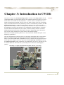
Chapter 3: Introduction to C9110i
C9110i is not only a very fast dispensing system, it is also a non stop system. C9110i
can dispense labels on goods with a speed of up to 200m/min with an accuracy of ±1.5mm.
Goods have to be endless and flat (Paperweb,...) and the sizes of the labels have to be
inside a specified range (length: from 20 to 95 mm; width: from 30 to 95 mm). The dispensing of a new label has first to be optimized by means of a well defined procedure, the dispensing optimisation for a label. This optimisation mainly consist in the choice and
adjustment of an Adapter, but also in setting some parameters on a super controller and on
the dispensing controller ( C91 Monitor). The optimisation procedure takes in consideration the relevant label-parameters (size, shape, material, release) and also of relevant
labelling-parameters (maximum goods-speed, maximum dispensing-speed, label-placement on the goods, placement for goods-sensor and dispensing-head).
General
Please find in chapter operating instruction in this manual the detailed description of the
dispensing optimisation.
Once this optimisation procedure is done, all necessary parameters and set point values
have to be assigned to this new label and saved (assign a parameter-set to a type of
label). Further the normal user or operator has just to call back the assigned parameters
and to adjust the adapter; that is the procedure of the dispensing initialisation. During
the labelling operation (after optimisation and initialisation) the user or operator has just
to feed the dispenser with label rolls (consumable) and to take off the backingpaper
(waste).
Assembly of a high speed standard system “C9110i” (non-stop).
Introduction to C9110i
8
The system is built up on two Collamat C9110 both mounted on one frame. The whole
system could easily be integrated in a production line and mounted just over the paperweb
(goods) on one underframe. For the optimal placement of the label on the goods, each
Collamat could be moved in 3 directions; one vertical, and two horizontal respectively as
inline and transversal to the paperweb direction
Concept
The dispensing system works in two ranges, a normal- and a high-speed range.
In the normal range the dispensing speed is synchronised with the goods speed; at the
moment of the impact between label and goods and during the whole application process,
both speeds (goods and label) have exactly the same value; which corresponds to the normal Collamat dispensing method.
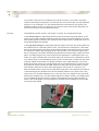
In the high speed range the dispensing speed is always lower than the goods speed and
the Collamat act as a delayed system in time. The result does correspond to a shift backward of the label position; the length of this backward shift will increase linearly according
the difference between dispensing speed and goods speed. This maximum delay length
does correspond to the fastest defined goods speed and could be easily measured on the
paper. This delay length is the most important input parameter to a dedicated super controller. The super controller take care of this delay and control the two Collamats by means
of an advanced time controlled GSC2-signal. A part from the super controller we also need
a special adapter which allows an optimal procedure of the label application. Once the
label has the right speed, the front label edge will be pressed between the press-roll and
the paperweb; at this moment the label will be torn away with the goods and the contact
area between label (end of label) and backing paper must be set to a minimum. The
distance between axis of press-roll and dispensing edge has to be adjusted in accordance
to the label length. Our adapters have all necessaries features so the super user or the
normal user can do these adjustments to a very easy way. Two adapters cover the whole
label ranges; adapter type 1 for short label length (from 18mm to 40mm), and adapter type
2 for long label length (from 35mm to 95mm). Both adapters have a press-roll which is
fixed on the usual adapter; the long adapter is equipped with an additional vacuum plate
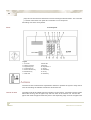
for driving longer labels.
Adapter type 2, with vacuumplate
Introduction to C9110i
5999.590-01A 02.08.99 SB
9
• Increasing production flow with remained accuracy
Advantages
• Based on known technologies
• Easy optimisation according to size, shape and material of labels
• Non-stop operating
• Adapted for inline finishing-line (target market).
actually the labelling-system is very often the slowest aggregate in an inline-finishing
plant and therefore is slowing down the whole line. Labelling speed up to 200 meter/
minute does correspond actually to a standard overall line-speed.
• Downsize the production costs (faster throughout)
• Faster return of invest
• manufacturing- & processing- paperindustrie,
Application areas
- direct mailing
- advertising
- marketing
• high production-capabilities for
- down sizing the cost
- increasing return of invest
• adjustment of the labelling-throughout
The high speed is built on two standard C9110i Collamat in a Non-Stop configuration. It
includes the usual components as traction unit, mechanical unwinder, rewinder and
module rail. New components are the air sling with electrical drive for label web (placed
between unwinder and traction unit) and the adapter. All these components are fixed to the
corresponding module rail.
Structure
The mechanical parts of a dispensing system are fixed on a vertical double columns with
horizontal & vertical adjustments units (handwheels). All these parts build up the mechanical dispensing part of one Collamat. One monitor is also fixed to the corresponding vertical
double columns with a dedicated bracket-set. Mechanical dispensing part and the monitor
build up one complete dispensing system. Each dispensing system is mounted on a horizontal adjustment unit (double steel tube) which is electrically driven. This does allow the
displacement of each dispensing system over the whole width of the Paperweb. Each horizontal adjustment unit is fixed on the legs of the frame. On this frame are also fixed an
operating box, a control box with a pressured air system fixed on it, encoder-wheel for
paperweb speed and goods scanners (mark readers). The mainframe with all parts could
easily be placed and fixed on a rack (see also installation).
Introduction to C9110i
10
The super controller is composed of two boxes, the I/O-box or MCS-IO (modular control
system input/output) and the terminal box or MCS-T. All parameters from the super controller could be visualised, edited, saved and recalled with this terminal. Each label has its
dedicated set of parameters which will be loaded in the MCS-IO. This loaded parameter
set in the MCS-IO is managing the actual labelling process. The terminal box can store up
to 99 parameter sets. The MCS-T communicate with the MCS-IO over a serial data-link.
The MCS-IO is fixed in the control box and the MCS-T could be connected temporarily to
the operating box for editing purposes.
The control box (fit at the rear of the C9110i) contains the main connection, transformator,
control relays, fuse, PLC, MCS-IO, opto-couplers and connection clamps. On a side wall
of the box is fitted the electrical power switch and the pneumatic or compressed air set.
This set is composed of one manual main valve, one maintenance unit (air conditioner)
with pressure input regulator, and two switch/regulator set for both dispenser.
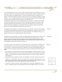
The operating box allows the control of the labelling system by means of buttons, lamps
and compact IO-panel for power-on, power-off, safety-off and setting the system operating
mode (non-stop, on, off); further and in non-stop mode, the operator can switch-on between Collamats and set the GSC-2 counter value. The MCS-T could be connected to the
MCS-IO over an 9 poles connector fit at the side wall of the operating box and could be
placed on a little desk just under the operating box.
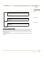
. Blockdiagram of the relevant components
Super
Controller
2
1
U
U
M
M
T
LSC
R
T
R
LSC
GSC
GSC
LSC:= label scanner; GSC:= goods scanner; M:= C91 monitor;
U:= unwinder; T:= traction unit; R:= rewinder;
The encoder and mark readers are fixed to the frame and can be individually and very
easily be displaced in each direction. The mark-sensor or goods scanner can be slided and
Introduction to C9110i
5999.590-01A 02.08.99 SB
11
fixed on a vertical guide bar for optimizing the distance between sensor and mark (mark
placed on the paperweb-formular or goods). This sensor (with the vertical guidebar) can be
slided and fixed on an horizontal guidebar in direction of the paperweb. The horizontal guidebar can him be slided and fixed along an horizontal profil rail which is fixed at a leg of
the mainframe (perpendicular to the direction of the paperweb-motion. Each marksensorsystem comprises the sensor, two guidebars (vertical & horizontal) and a profil rail fixed at
the corresponding mainframe leg. All fixing mechanism are done with screws. This positioning system allows to place the mark reader (or mark sensor) over the wall paperweb
width and also over the right place in paperweb direction.
The contact line between adapter roll and paperweb does correspond to the impact line of
the labelling process; this line has to be placed just over the axe of a back pressure roll.
The label will be taken in sandwich there and the dispensing is done under stable conditions. The placement of the adapter in paperweb direction is done with the horizontal adjustment part of the double column (driven by handwheel). The placement of the adapter in
direction of the paperweb width is electrically driven (two steel tube with a traction spindle
placed on each mainframe leg for guiding and traction of the corresponding double
column). The vertical position of the adapter is done with the vertical adjustment of the
double column (driven by handwheel).
The encoder delivers the pulses as a frequency directly proportional to the paperweb
speed. It is composed of a friction wheel which is driven by the paperweb. The impact
points between friction wheel and paperweb does correspond to a short friction segment
equal to the thickness of this wheel. This friction segment is parallel to the adapter roll and
needs also a back pressure under the paperweb. For this reason this friction segment will
be placed over the back pressure roll of the master collamat (axe over axe). The encoder
can be positioned over the whole paperweb area of concern in the same manner as the
mark reader. This encoder positioning system comprises a vertical guidebar for the sensor
with sliding and fixing possibilities, the mark reader, a cross profil rail between the mainframe legs for sliding and fixing the vertical guide bar; the cross profil rail can be slided in
direction of paperweb width and fixed on two other profil rails fixed each on the inside wall
of the corresponding mainframe legs.
The whole structure offers a great flexibility while installing or optimising the labelling process.
Introduction to C9110i
12
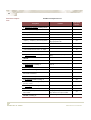
Standard components
Standard components list
Designation
High-speed
specific
Function
2 * dispensing system consisting each of:
- mechanical part consisting of
- Unwinder (midi)
- air sling
no
smother feeding of labelweb
yes
- traction unit
- adapter_1 & adapter_2 (short & long labels)
no
guiding & pressing the labels according high-speed rules
yes
- rewinder
no
- module rail
no
- vertical double columns with h. & v. adjust.
no
- monitor
1* super-controller consisting of:
compensation for dispensing time
delay
yes
controlling high-speed & Non-stop procedures
yes
- MCS-IO
- MCS-T
1*electric-pack consisting of
- operating-box
- control-box containing:
- Trafo, fuse, relays, PLC, connection-clamps,
main-switch and MCS-IO
- 2*set of indication-lamps
1*air pressure pack consisting of:
yes
- air conditioner, pressure-regulator, injector
(vacuum), valves,
1*sensor pack consisting of:
Introduction to C9110i
yes
- 2*GSC-scanner (mark-reader) with brackets
fixing-/adjustment possibilities
- 1* encoder (1000 Imp./220mm revolution)
with brackets
fixing-/adjustment possibilities,;
high resolution for super controller
yes
1*frame consisting of:
special design
yes
5999.590-01A 02.08.99 SB
13
Designation
- two legs tube system with lateral consolidation
Function
High-speed
specific
could be transported by stackers
- 2* horizontal double columns with electrical
driven adjustment for mounted dispensing
system; each column fixed on the respective
frame-leg.
- frame mounting set: 4*fixing angle with guiding cones to be fixed on the underframe
4fixing angle with guiding holes
Introduction to C9110i
14
Introduction to C9110i
5999.590-01A 02.08.99 SB
15
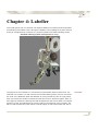
Chapter 4: Labeller
The overall goal is that our customer can dispense labels as accurate and fast as possible.
The handling of the labels is done through the labeller. The knowledge of its parts and how
those can be adjusted will contribute to a smother workflow and better labelling results.
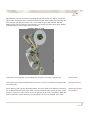
Standard labelling-system with optional air sling.
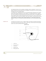
The purpose of the unwinder is to continuously provide labels without interference. The
unwinder unit consists of a midi unwinder and an label-airsling with a motor for a first traction level of the labelweb. When the labelweb is moving the dancing arm is to get pulled
down and causes the winder to release its brake and cases to feed more paper. When no
more paper is needed, the dancing arm shall be adjusted so that it turns back to its original
position by itself. This adjustment is done by setting a torsionspring of the unwinder. The
dancer roller represents a paper buffer to quickly supply or take up the label web. Due to
Unwinder
Labeller
16
the adjustable spring force the feeding of labelweb could be optimized in function of the
demand (minimum of hits and tension on the labelweb). The spring force is set by turning a
knurled knob in the according position.
A variable portion of labelweb hangs up on two horizontal axes and builds up an vertical
falling down labelweb-airsling due to the gravitation. On labelweb demand, the deepest
point of the airsling rise up and the length of the sling becomes shorter. This deepest point
will be detected at two fixed levels (high and low) by two sensors. This two sensors will
respectively switch on and off the traction motor of the airsling. The airsling acts as a two
points regulator; the airsling is able to feed continously on a soft manner (no hits and
variation of tension on the web) the demanded labelweb from the following dispensingsystem.
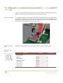
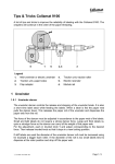
Traction unit
The purpose of the traction unit is to keep the paper web steady and tight before dispensing and after dispensing having the paper in a pull state, which causes the entire paper
web to move and is the actual feed of the labels.
Traction unit
Labeller
1
Traction roll
2
Back pressure roll
3
Knurled knob
4
Deflection shaft
5
Backing paper web
5999.590-01A 02.08.99 SB
17
Turn the knurled knob by 90 ° in order to ease the back pressure roll at the traction roll. For
right hand version turn clockwise otherwise counterclockwise. Position the back pressure
roll in the middle of the backing paper. In order to do this the set screw needs to be
release. If the back pressure roll not is under tension an error message will appear: “paper
traction / -end”. The paper brake has to be fix and hold the label web steady. Before labelling the entire label web must be stretched to avoid label errors.
The traction unit as well as the other peripherals are mounted on a module rail. All parts
are surfaced treated to protect from corrosion. The special coating of the traction roller
affords permanent torque transmission to the paper web without slip. The force of the
paper web brake is adjustable. The traction roller can be easily turned by hand during
Power off for easily threading and installing the paper web.
The purpose of the adapter is to dispense the label on its product. There are two adapters,
one for the labels with a length under 30 mm and one between 40 and 95mm. The no mans
land between 30 and 40 mm depends on the label stiffness, form, adhesive and for the
optimal solution we recommend the super user to test both.
Adapter
The purpose of the rewinder is to collect the baking paper and make it easy to remove for
the user. If the C9100i is switched on without having fixed the backing paper, or if the
backing paper is torn apart during the application, the dancer will shot up to maximum
speed position but will stop after 8 rotations. It can be restarted when the dancer is at stop
speed position and a reset of the stop command.
Rewinder
The power supply and the electronic control are built into a metal casing. All peripherals
are connected to a connector box connected to the monitor back panel by one single Dsub-connector. A large heat sink allows to operate the monitor without additional fan. The
monitor can be mounted in various positions. The monitor contains the following assemblies:
Monitor
• Noise filter with voltage selector. The noise filter keeps EMI outside to prevent any interference with the electronic control and also prevents EMI to be transmitted to the mains
supply. The voltage selector allows versatile adaption of the power supply to different
main voltages.
• Transformer which supplies the power for the labeller, unwinder, rewinder and monitor.
• Interface p.c. board which connects the motor drive to the power supply and to the controller. The electronic part of the power supply is also installed on the interface p.c.board
which shapes all input and output signals to and from the controller.
• Controller p.c.board comprises a Hitachi H8/5332 micrcontroller, EPROM with a software, LC-display and short -stroke keyboard and the nonvolatile memory. The LC-dis-
Labeller
18
play has four lines with 20 characters each and a background illumination. The controller
p.c.board communise from panel and controller in one component.
All settings are done via keyboard.
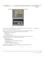
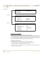
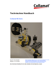
Panel
monitor panel
Legend
1. 4 line LCD
2. Labeling mode key
3. Programming key
4. Configuration key
5. Service indication key
6. RUN/STOP key
8. RUN LED
9. ESC key
10. Keyboard 0...9
11. dot Key
12. ENTER key
13. UP key
7. STOP LED
14. DOWN key
Actions
The actions here mentioned are adjustments needed to optimise the system. Daily chores
such as threading the labeller will also be mentioned here.
Thread of label
Labeller
The paper web will be pulled from the unwinder over the dancer, in between the two rollers
before the air sling, into the paper loop and from there to the traction unit. Conduct the
paper web under the paper break and pull it to the dispensing edge. Pull out the paper web
5999.590-01A 02.08.99 SB
19
approximately 1 meter to make the threading through the traction unit easier. Thread the
paper under the traction roller, between the traction roller and the back pressure roller and
then over the back pressure roller. Pull out the clamp strap on the rewinder. Pull the
backing paper over the dancer to the rewinder core and fix the clamp strap again. Please
make sure that the entire paper web is stretched
Unwinder with air sling.
Compress the two handles on the holding disc and pull it out of the unwinder core.
Take off disc
Take off the disc and the old label roller. Put on the new one, thread the unit and put back
the holding disc.
Change label roll
Due to dancing arm type and mounting position the force needs to be adjusted. This force
can be adjusted with a spring force. After you have dismantled the housing around, a knob
with a lot of holes in it can be seen. The force spring is stuck in one of the holes. When the
knob is pressed in, turned and left in a new position, the force is changed. If the force
Adjust spring force
of Unwinder
Labeller
20
spring is pressed harder, the dancing arm moves more easily to its original position but it
takes more force to move the dancing arm down to get more paper.
Adjust the adapter
The required spring force can be adjusted with the cylinder head screw on the flap adapter.
The force gets softer when the screw is turned clockwise. The slope of the flap adapter can
be changed. To release the knob two turns is needed. Extend the screen by hand, position
the adapter in required position and fix the knob again.
Adapter with vacuum plate.
Adjust the press
roll
Depending on your labels and your goods, you want to adjust the press roller.
Change in the
monitor
Menu Tree
Userlevel
Run/Stop mode
Labelling Mode
Labeller
--Label jog
Operator
Stop
--Select program
Operator
Stop
--Information display
Operator
Run
--Reset counter
Operator
Stop
--Preset counter
Operator
Stop
--Select counter
Operator
Run
5999.590-01A 02.08.99 SB
21
Menu Tree
--Reset nonstop
Userlevel
Run/Stop mode
-------------
-------------
--Change program
Super User
Stop
----Label scanner sensitivity
Super User
Stop
----Label length
Super User
Stop
----Label suppression
Super User
Stop
----Presdispensing
Super User
Stop
----Position
Super User
Stop
----Speed
Super User
Stop
----Maximum speed
Super User
Stop
----goods suppression
Super User
Stop
----Labelling mode
Super User
Stop
--Profiling
---------------
---------------
--Program name
Super User
Stop
--Program preset
---------------
---------------
--User menu
Super User
Stop
--Language
Super User
Stop
--User level
Super User
Stop
--Error handling
Super User
Stop
--Nonstopmode
---------------
---------------
--Adaptermagnet
---------------
---------------
--Motor direction
Super User
Stop
--Polarity ifeed
---------------
---------------
--Software-version
---------------
---------------
--Error sequence
---------------
---------------
--Self-test
---------------
---------------
--Remote control
---------------
---------------
Programming
Configuration
Service functions
Labeller
22
Menu Tree
See also
Userlevel
Run/Stop mode
--Working time
---------------
---------------
--Motor running
---------------
---------------
RUN/STOP
Operator
Select
• Operating instructions C9100 Traction unit
• Operating instructions C9100 Monitor
• Technical handbook C9100
Labeller
5999.590-01A 02.08.99 SB
23
Chapter 5: Super Controller MCS
The C9100i super control is used for the computerized control of labelling. The Super Controller MCS consists of one terminal unit with the designation “MCS-T”, and one control
unit with the designation “MCS-IO”. The terminal unit and the control unit are linked together by means of a cable. The power supply is provided by the MCS-IO which supplies the
input terminal with 24 VDC via this cable. The input terminal is only used for the purpose of
programming and storage of parameters. Once programmed, the MCS-IO controllers can
also operate without the terminal unit. All the parameters of the controller are classified in
two groups with the respective designation “Program” and “Configuration”. The program
parameter group can be set by an operator (normal user). The configuration paramater
group belongs to an engineering activity and has to be set by a trained user (the super
user). Programs and configurations can be loaded from the MCS-IO controllers. The super
Control system can communicate in several languages. The desired language can be set
in the “configuration” menu. Dimensional units can also be set. Length in mm or 1/16” and
speed in m/min. or feet/min.
structure
The collamat detects the goods at a determined place over the paperweb (or conveyor)
and start the labelling process (start of labelweb motion) after a delay time which is
function of the position value and a predetermined labelling speed. The collamat is working
in the synchronized labelling mode at low speed range; the speed measurement of the
goods is done with the signal of an encoder. The synchronized mode means that the labelling speed matches the speed of the goods at the moment of dispensing. At high speed
range, the collamat will switch to the fixed dispensing mode ( or asynchronous labelling
mode); that means the labelling speed is done at a fixed value independendly of the actual
goods speed. This changes of labelling mode are driven with the state of the collamat input
signal “ready”. All values of the position, fixed labelling speed, etc are set as parameters
on the collamat; see also the op erating manuals “C91monitor” & “traction unit”. In the high
speed range the labelling process acts as a roughly first order delayed process; the result
is a linear backward moving position of the label on the goods, which increases linearly
with the goods speed.
collamat
The super controller (MCS-I/O) compensates this delay by generating an approriate new
GSC- signal which is connected to the collamat. The MCS-I/O is, therefore from an electrical point of view, placed between the goods detection systems (goods scanner or mark
reader in case of formulars) and the collamat. The signal of each mark reader (GSC =
goods scanning or trigger) and the encoder will be connected to the corresponding inputs
fitted at the rear panel of the MCS-I/O with the respective denomination 1, 2, G; 1 = Trigger
1 for the collamat A (master), 2 = Trigger 2 for the collamat B (slave) and G = encoder for
the speed measurement of the paperweb. Both trigger signals will be delayed according to
connection
Super Controller MCS
24
a sophisticated computerized algorithmus and appear again on 4 output connectors; outputs 1 & 2 are dedicated to the collamat A (master) and outputs 3 & 4 to the collamat B
(slave). Output 2 and output 4 are connected to the GSC-2 inputs of respectively collamat
A and collamat B (goods scanning). The encoder signal is divided by 10 and appears as
exactly the same signal (encoder-signal / 10 ) on the output connectors 5 & 6. Output 5
and output 6 are connected to the GSC-1 inputs of respectively collamat A and collamat B
(encoder input). The cabling of the collamat does correspond to the measuring method
with incremental encoder. All the wirings between super controller and C91 monitor are
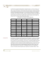
already done in accordance to the following wiring table.
wiring table for the super controller (MCS-I/O)
MCS I/O input
MCS I/O output
C91 monitor (I)
Trigger 1
mark reader A
Trigger 2
mark reader B
G (encoder)
encoder
channel 1
channel 2
GSC-2, A
channel 5
GSC-1, A
C91-A on/off (O)
I/O, out 1
ready, A
channel 3
GSC-B counting (I)
channel 4
GSC-2, B
channel 6
GSC-1, B
I/O, In1
C91-B on/off (O)
I/O, out 2
Super Controller MCS
internal PLC (I/O)
GSC-A counting (I)
level, S
configuration
peripheries
ready, B
As said before, the maximum backward shift of the label position is reached by the highest
goods speed. This length can be measured and put in the MCS-T (terminal) as a parameter whith the designation “compensation length”; the value of this highest goods speed
does correspond to an other parameter “vmax product”. The highest possible goods speed
is determined by experiences and depends mainly from the size of the label. The best
compensation accuracy is reached by setting the parameter value of “vmax product” just a
little higher (for instance 5%) than the effective possible highest goods speed. The switching between fixed and synchronized dispensing modes on the collamat is set at the
value “vmax collamat” which is an other configuration parameter of the controller. The
super controller sets an I/O output (out 1 for Collamat A and out 2 for Collamat B) in
function of the actual measured goods speed compared to the defined value for “vmax
5999.590-01A 02.08.99 SB
25
collamat”. This two outputs drive the ready-signals of the collamat (see wiring table
above). All these mentioned parameters belong to the group “Collamat-Parameter” inside
the configuration parameters of the controller; below a table of all “Collamat Parameter”
with the corresponding function description.
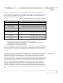
Table of “Collamat-Parameter” on the super controller
parameter designationt
function
“vmax product” *
set the maximum possible speed for the goods *
“Trigger distance”
length between mark sensor and dispensing edge
“vmax Collamat”
switching value between low speed range and high speed range
“Position Collamat
Compensation length
copy of the position value, set as parameter on the collamat
length value to be compensated at “vmax product”
“Correction length 1:” **
“at speed v1:”
length value 1, as linearity correction
for the speed value 1 ( point of support )
“Correction length 2:” **
“at speed v2:”
length value 2, as linearity correction
for the speed value 2 ( point of support )
“Correction length 3:” **
“at speed v3:”
length value 3 as linearity correction
for the speed value 3 ( point of support )
* : this parameter is valid for both dispensing unit (Collamat A & B);
all other parameters exist twice and belong to a set, each dedicated to their respective
dispensing unit (Collamat A and Collamat B).
**: this parameters are generally not configurated
Aside the configuration set “Collamat Parameter”, we have also the set ”Channel parameter”, the set “MCS-IO controller” and the set “MCS-T userinterface. All these 4 sets belong
to the Configuration Group and are explained more in details below, under point “menue
structure”.
The program group with the designation “Progam editor” is composed of two sets with the
respective designations, “length editor” and “clear channel”. The main purpose of the
“length editor” is to define the label position on the goods with respect of the formular
edge; the black mark on the formular does coincide with the formular edge (beginning of a
new formular). A serie of 32 labels could theoretically be programmed and placed with one
black mark (GSC-Trigger). The set “clear channel” allows to reset already programmed
channels. The controller has 4 channels which correspond to the 4 outputs, output 1 to
output 4, described above under connection. Channel 2 and channel 4 drive GSC-2 of
Collamat A respective Collamat B. Channel 1 and channel 3 are the respective copies of
channel 2 and channel 4 and have to be therefore progammed absolutly identically. They
are connected to the internal PLC for counting the goods crossing the respective mark reader.
Programming
Super Controller MCS
26
Remark:output 1 & 3 are always active, also when the corresponding dispenser (collamat)
does not work. In comparison output 2 and 4, drives directly the coresponding
collamat over the GSC-2 signal and can for this reason only be active when the
assigned dispenser works.
More details below, under point “menue structure”.
memory
All parameter groups (program and configuration) could be saved and read back from a
non volatile memory in the MCS-T. From there the corresponding sets could be edited and
saved back under a dedicated Nr. for the programming-group and for the configurationgroup. Each group Nr. could also be downloaded or read back from the MCS IO. Inside the
MCS IO, only one group for respective the Program and the Configuration is stored in a
non volatile memory. This actually stored pair of groups makes the system working.
The MCS IO is able to store up to 99 groups. Each pair of group Nr. could be assigned to a
label type.
More details below, under point “menue structure”.
Human machine
interfaces
The human/machine interface is build up of an operator box for controlling the system
mode (see below, under operating box) and the terminal of the super controller (MCS-T)
for parameters (program and configuration) and visualisation.
Both elements are accessed from the front of the system; the operating box is fixed on a
tube and the terminal is placed on a little desk fixed on the same tube under the operating
box. A connector fixed on the wall side of the box does allow the connection between the
two MCS units (MCS-IO & MCS-T).
Super Controller MCS
5999.590-01A 02.08.99 SB
27
operating box and Terminal unit of the super controller.
The box has an IO-Terminal with 6 buttons, a LCD display, two push buttoms, three switches, an error lamp and an emergency stop buttom.
operating box
The operator can with the terminal, select between three system operating modes, and in
case of Nonstop mode set the number of goods between the two collamats.
The three system operating modes are:
- non-stop (0),
- both collamats active (1),
- both collamats inactive (2)
The use of the operating box, including the terminal is self explaining. Aside the terminal,
following buttons are assigned to functions as described below.
three switches for:
- release pneumatic (on/off)
- release collamats (on/off)
- reset for new starting procedure after failure and stop state.
two push buttons for:
- switch on the control logic after power on.
- switch between collamats while in nonstop mode
The connector for the external removable link with the MCS-T, is internally connected
(fixed wiring) with the MCS-IO.
Super Controller MCS
28
Terminal
The terminal (MCS-T) is build up of a LCD display and a set of push buttons. The following
general rules explain how the user can navigate, edit, store and recall all the necessary
parameters.
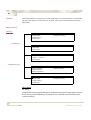
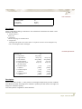
Menu structure,
main (1),
Main menu
Program editor
configuration memory
Program memory
Configuration
program (2),
Program editorain mee
Length editor
Clear channel
Program memoryain mee
Program - - > MCS-IO
Edit program
Program < -- MCS-IO
Clear program
configuration (3),
Configurationain mee
Channel parameter
Collamat -Parameter
MCS-IO controller
MCS-T userinterface
Configuration memoryee
Program editor
configuration memory
Program memory
Configuration
Description
(1), main:
navigation between programming and configuration modes for the purpose of parameter setting and file handling of parameter sets (call and store from/to the non
volatile memory).
Super Controller MCS
5999.590-01A 02.08.99 SB
29
(2), program:
- setting placement of one or several labels (up to 32) referenced to the formular
edge norml user
- setting the pulse width (in duration) at output 1 to 4.
(3), program memory:
-
read, save the parameter sets (up to 99) for programming in the MCS-terminal and read/
save from/to the MCS-IO.
(4), configuration:
-
setting all the necessaries parameters for speeds (dispensing, goods) and delay-compensations.
(3), configuration memory:
-
read, save the parameter sets (up to 99) for configuration in the MCS-terminal and read/
save from/to the MCS-IO.
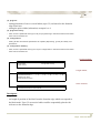
Program editor
Program editor
Length editor
Configuration memory
Clear channel
Length editor,
Length editor
Controller/Channel.# 1.1
[ . .1]
[ . .2]
[ . .3]
[ . .4]
[ . .5]
Distance from edge:
Pulse duration (at vmax):
Clear channel,
Clear Channel
Controller/Channel.# 1.1 Clear channel
Description
Length editor:
- set length of position of the label from the formular edge which corresponds to
the black mark. Up to 32 successive labels could be sequentially placed with
reference to the formular edge.
Super Controller MCS
30
The start of each position is related to the edge of the sheet. This enables the position of
individual labels to be changed without affecting other labels.
r chExample of positionannel
-
The pulse duration for each output of the corresponding has to be set in time; this time
does correspond to the pulse duration (time) at maximum goods speed.
Clear channel:
- select the output channel; select clear channel and press enter taste. The correponding parameters value will be cleared.
Super Controller MCS
5999.590-01A 02.08.99 SB
31
Program memory,
memory
Program memory
Program - - > MCS-IO
Edit program
Program < - - MCS IOy
Clear program
Clear program
Clear program
Program Nr.: #10
Clear program
edit program
Edit program
Program Nr.: #10
Length editor
Description of program memory
The programming parameters of the MCS-IO can be read into and stored in the operator unit. From
there, these saved parameters can be transferred back to the MCS-IO. Saved positions can be
adjusted without disturbing or interrupting operation. This makes it possible to prepare the next setting during production.
The length editor does correspond to the procedure already described above under “Program editor,
length editor”.
Super Controller MCS
32
Configuration
Configuration
Channel parameterr
Configuration memory
MCS-IO controller
MCS-T user interface
channels
Channel parameterain mee
Controller/Channel: #1.1
. . . . 1. Trigger source:
# trigger 1
. . . . 2. Vmin:
# 0 [m/Min]
. . . . 3. Reaction if v<vmin:
# clear sequence
. . . . 4. Enable input:
# off
controller
MCS-IO controllerain mee
Controller: #1
. . . . 3. Trigger source:
# trigger 1
. . . . 4. Encoder pulses/1000mm:
# 4550
. . . . 5. Trigger 1 input:
# (-) input (normal)
. . . . 6. Trigger 2 input:
# (-) input (normal)
. . . . 7. Station number:
#1
. . . . 8. Program version:
4.4
Description of configuration
Each channel is triggered by one of the two signals Trigger 1 or Trigger 2.
The signals Trigger 1 and Trigger 2 originate from the relevant external trigger input (black-mark-sensor). The triggering edge is programmable, but it is recommended that the active (connecting) edge
is to be used. After triggering, the trigger is blocked until the position of the last label. This means that
if you have programmed 32 labels, the trigger will be blocked all this distance.
Interrupting/cancelling the labelling
The labelling process can either be interrupted or cancelled in the event of:
• the speed falling below the minimum speed set for a particular channel
• the external enable contact (ENABLE input) being opened.
• emergency botton has been pressed (In the event of a fault the alarm output will be connected until the fault is rectified.)
Super Controller MCS
5999.590-01A 02.08.99 SB
33
user interface
MCS-T user interface
1. Station number:
#1
2. Language:
Deutsch
3. Length unit
# [ mm ]
Description
All the parameters relating to the MCS-T user interface are located in the "MCS-T user
interface" sub-menu.
"1. Station number.:"
Always nr.1
"2. Language:"
Choose a language of communication.
"3. Length unit:"
All lengths and speeds can be either metric or imperial. The units can be changed at any
time; saved lengths remain unchanged.
collamat parameter
Collamat parameter
Controller: # 1
#1
. . . 1. vmax product:
200 [ m/Min ]
. . . 2. Trigger distance:
100.0 [ mm ]
100.0 [ mm ]
. . . 3. Vmax collamat:
80.0 [ m/Min ]
80.0 [ m/Min ]
. . . 4. Position collamat:
. . . 5. Compensation length:
2.0 [ mm ]
2.0 [ mm ]
50.0 [ mm ]
50.0 [ mm ]
. . . . . (at vmax product)
. . . 6. Correction length 1:
. . . . . at speed v1
. . . 7. Correction length 2:
. . . . . at speed v2
. . . 8. Correction length 3:
. . . . . at speed v3
[ mm ]
[ mm ]
[ m/Min ]
[ m/Min ]
[ mm ]
[ mm ]
[ m/Min ]
[ m/Min ]
[ mm ]
[ mm ]
[ m/Min ]
[ m/Min ]
Description
All the parameters, exept “1. vmax product” are assigned respectively for each collamat.
The values at the left are assigned to collamat A (master) and the value on the right are
assignd to collamat B (slave).
The vmax product is appllied on both collamats.
Super Controller MCS
34
-
Trigger distance between dispensing edge and mark-reader
-
Vmax collamat, max dispensing speed
-
Position collamat is the copy of the position parameter on the corrsponding collamat
-
Compensation length is the corresponding delay length at vmax product that has to be
compensated.
-
Correction length x, is a linarity correction at corresponding speed x; normally these
three correction are not to be used.
configuration,
memory
Configuration memoryain mee
Parameter set - - > MCS-IO
Parameter set < - - MCS-IO
Clear parameter set:
Parameter set - - > MCS-IOain mee
Set Nr.:
Controller: . 1
Transfer parameter set to MCS-IO
Parameter set < - - MCS-IOain mee
Set Nr.:
Controller: . 1
Read parameter set from MCS-IO
Parameter set - - > MCS-IOain mee
Set Nr.:
#1
Clear parameter set
Description
The configuration parameters of the MCS-IO can be read into and stored in the operator
unit. From there, these saved parameters can be transferred back to the MCS-IO. Saved
parameters can be adjusted without disturbing or interrupting operation. This makes it possible to prepare the next setting during production.
Super Controller MCS
5999.590-01A 02.08.99 SB
35
menu tree
Menu Tree
Userlevel
Operating
mode
Explanation
Main menu
--Program editor
Super user
On
----Length editor
Super user
On
----Clear channel
Super user
On
--Manual mode
------
------
--Program memory
Operator
On
----Program --> MCS-IO
Operator
Off
Transfer program to MCS-IO
----Program<--MCS-IO
Super User
Off
Read program from MCS-IO
----Clear program
Super User
On/Off
----Edit program
Super User
On/Off
------Length editor
Super User
On/Off
------Stich mode
Super User
On/Off
--Configuration
Super User
On/Off
----Channel parameter
Super User
On/Off
Display/alter the parameters of individual channels in the MCS-IO controller
----MCS-IO Controller
Super User
On/Off
Display/alter the parameters of individual MCS-IO controller
----MCS-T user interface
Super User
On/Off
Display/alter the parameters of the
MCS-T user interface
----Collamat Parameter
Super User
On/Off
----Parameter set -->MCS-IO
Operator
On/Off
----Parameter set <--MCS-IO
Super User
On/Off
----Clear parameter set
Super User
On/Off
--Configuration memory
Super Controller MCS
36
Super Controller MCS
5999.590-01A 02.08.99 SB
37
Chapter 6: Operating Instruction
When carring out operating instructions you have to be aware of that C9100i continues a
monitor, a MCS-Terminal and an operating box. In principle, each MCS-T user interface,
each MCS-IO controller and the individual channels in the MCS-IO controller must be configured. The configuration parameters are divided into the following Nonstop control with a
PLC.
Introduction
Nonstop
Since the nonstop function is controlled by a PLC the Collamats have to be configured in
normal-mode. That means they should NOT be configured in Master/Slave mode but configured as single dispensers in the monitor menu tree/programming/ change program/ labelling mode/ normal labelling. The PLC has both of the Collamat goods signals as input
(connected to output 1 and output 3 of MCS-IO), and control the release of both the
Collamats. This means that the PLC controls the entire nonstop function, counts the products in between the Collamats and the PLC controls the delay of run/stop of the relevant
dispenser. When in use in an endless-forms operation the PLC must be told how many products there are between the Collamats at the start. This is done at the control box with the
key GSC.Operating Instructions.
The operating instructions are classified in three groups:
•
General
the normal operating, where the adapter and all parameter are already set. The operator or normal user starts/stops the system, feeds it with the consumable (label rolls)
and removes the backing paper.
• the initialisation, where the operator has to adjust the adapter and set all parameters in
the monitor and super controller according to already known values.
• the optimisation, where the super user has to define the adapter adjustment and also to
define all the needed parameters in the monitor and super controller in case of a brand
new label. The super user is a trained person who understands the optimisation rules
described below.
• Power on sequence
- switch on the main switch on the control box (external side wall)
- press the “on” button on the operating box; be sure the emergency switch is set to off
- set the “Collamat disable switch to on; right position
- set the run/stop switch off each monitor to “run”
- set the “vacuum enable” switch to on, right position
- if the error-lamp is lighting, turn the reset key to the right and go back to the left.
Normal operating
• Select the system mode on the programming-panel (panel on the operating box)
one of three system-modes can be selected by the programming-panel;
Operating Instruction
38
“non stop”, “on” (both Collamat), ”off “(both Collamat)
- press key 4, press enter key, set the right number by the increment/decrement arrows-key
according following rule: 0:= “non stop”; 1:= “on”; 2:= “off”
The normal mode is the “non stop” mode; the other two modes will not further be of interest.
•
Set the GSC2-3 counter value
In non-stop mode it is important to declare always the amount of goods between the two
Collamats working respectively as a master and a slave.
- press key 3, and select the right value with the corresponding “arrow-key”
remark: before selecting a new menu-tree with the adequate key-number, press always first key
“F1”, and then press the wished key.
•
Release the labelling procedure
- set the “Collamat disable switch to off; left position; one of the Collamat is labelling
- changing the active Collamat is done by pressing the “Collamat Switch” button. Each time this
button is pressed for a brief moment, the active labeller will be changed.
Each Collamat will automatically stop when consumable-stock are low (LLO-signal) or
waste are full (Rewinder full signal). The other Collamat will automatically start at the right
moment without missing a label on a goods or labelling twice a goods. The non stop procedure, the placement of the new label web and the take-off of the waste are explained in the
several manuals of the Collamat 9100.
Initialisation
The operator has to initialise the system for a label that is already optimised. This means
that the selection and all the adjustment-values of the adapter are already documented. All
necessaries parameters are saved in the appropriate program set-number and configuration.-number in respectively the monitor and the super-controller (MCS-T).
• Adapters
- select the right adapter (adapter_1 or _2 for respectively short or long labels).
- The adapter has the necessaries ruler with 0.5mm resolution on it; that feature allows the operator to exactly reproduce the initial adjustments.
- adapter_1 (short label)
- D1: distance between axe of pressure-roll to dispensing edge
- adapter_2 (long labels)
- D1: distance between axe of pressure-roll to dispensing edge
- D2: position of LSC-pack referenced to the holm
- D3: distance between axe of pressure-roll to vacuum plate (normally fixed for all labels)
• Program set on the Monitor
- select the corresponding program-number with the main parameters “Predispensing, Position,
Speed”;
• Program set and Configuration set on the Super controller (MCS-T)
For each label the operator has to select the corresponding No and Configuration No from the
MCS-T and to down load it to the MCS IO.
- select program memory
- select Program to MCS-IO
Operating Instruction
5999.590-01A 02.08.99 SB
39
- select the corresponding Program No.
- transfer the program to the MCS-IO
see also Chapter 5, “Super Controller MCS
• Go to normal operating
Once the initialisation is done, the operator goes to the normal operating mode and start the
labelling system.
adapter selection
With each new label the super user has to define the adapter (selection & adjustments) and the
several parameters for the monitor and the super controller.
Optimisation,
• Adapters-selection
Selection is made in consideration of the label-length;
if the length is over 40mm select always adapter_2 (long labels);
if the length is lower than 30mm select always adapter_1 (short labels)
else both adapter could be used but the experince will guide the selection in consideration of
label-shape, -stiffness and -adhesive.
adapter selection
• Adapter-adjustments, ;
- the contact between pressure-roll and paper does correspond to a line, the contact-line.
- setting rule 1:
the distance between contact-line and dispensing-edge is the bridge-length (or D1) and has
a value equal:= (label-length - 2mm);
All length could be referenced to a standard label of 50mm length with following adjustment:
- D1 = 53 (on the D1-ruler)
Examples
- if the label has a length of 60mm, we place the adapter so we can read 43 on the ruler.
- if the label has a length of 40mm, we place the adapter so we can read 63 on the ruler.
adaper adjustments
• Monitor parameter (program), rule 1
- predispensing: set the value for a sliding contact between front label edge and pressure-roll
all other parameters are constant with followingvalue:
- position: 0mm
- speed: measuring-mode, encoder (2.20mm), max. speed 60m/Min.
parameters
Operating Instruction
40
• MCS-T (program & configuration), rule 1
- compensation-length: set to 0mm;
- start labelling-process at 60m/Min goods-speed;
- start labelling-process at maximum goods-speed, measure the delay-distance between the
label-position for the two goods-speeds.
- put this value as the new compensation-length.
All other values remain constant
Store this parameters to a label corresponding program-number; the normal user or operator
could always select them.
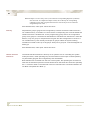
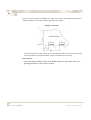
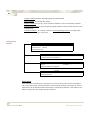
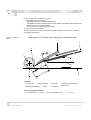
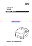
Label adjustment,
figure
Label position on the adapter while Stop phase in dispensing mode
1
6
8
c
3
2
5
b
a
d
4
7
Definition:
1: vacuum plate;
2: dispensing edge;
5: labelweb (backpaper);
6: label;
3: pressroll;
4: paperweb (formularweb)
7: contact line
8: touch line
Mechanical adjustment rules:
b + c = label-length;
Operating Instruction
d:= D1 = (a + b) = {(label length) -2mm};
a:= c - 2mm
5999.590-01A 02.08.99 SB
41
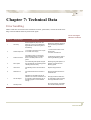
Chapter 7: Technical Data
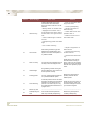
Error handling
When a fault has occurred on the Collamats’ monitor, press enter, correct the fault according to the list below and then press enter again.
Error messages
Monitor Collamat
Error #
Error message
Error cause
Solution
1
Not ready
External appliance (flat printer, hotsatmp etc.) has not yet released the
signal READY at the starting time of
the labelling.
2
TUNIT/ Paper end
1. The lock in the traction unit is open.
2. The label roll is empty
1. Close lock of traction unit or
paper brake.
2. Insert a new label roll
3
Position too short
The position value is to low for the
actual labelling speed. The label is
stuck in the false position on the
goods.
Increasing the position value or
reducing the labelling speed
4
Max. speed
The measured goods speed is higher
than the entered max. labelling speed.
Labelling becomes faulty.
Reducing the goods speed or, if
possible, increase the max.
labelling speed.
5
Label stock
The labelling stock of the unwinder is
full.
Replace empty label roll.
6
Rewinder full
The rewinder disk of the rewinder is
full.
Remove the label roll from the
reewinder disk.
7
No LSC-Adjust
Adjustment of the label scanner not
possible. The scanner is defective or it
is scanned on label instead of gap, or
the baking paper is not transmitted
enough.
Shift gap under the label scanner and adjust it again. Possibly
exchange defective scanner.
8
Nonstop-mode
Reduce the cadence. Reducing
time activated by the READY
signal.
Do not do anything, not applient
with C9100i nonstop with PLC
Technical Data
42
Error #
9
Error message
Label too long
Error cause
Solution
A leading label edge could not be
scanned within the entered label
length. The cause of this error can be
as follows:
• Enter in general the label
length two times.
• Missing labels on the label web
• Adjust suppression of
label scanning
• Slippage of the traction unit or
loss of stepper motor due to hits on
the label web or too high frictional
force.
• Value of label length is entered
too short
• Correct predispensing
• Check label scanner and
possible clean it
• Reduce friction force of
entire label web
• Predispensing greater than label
length
• Error of label scanning
10
Technical Data
LSC Counter
When braking the label, a gap was
detected during predispensing. This
happens in the case of transparent or
very reflective labels.
• Adjust of suppression of
label scanner
• Optimise the positioning
of label scanner
• Optimise the label sensitivity
Switch off the motor. Wait 10
seconds before switching on
again. If the error has not disappeared, the monitor is damaged
and has to be repaired by a specialist.
11
Drive not ready
The motor drive card indicates that it is
not ready to drive the stepper motor.
12
Undervoltage
During labelling a mains causing the
data to be backed up. The monitor continues to operate normally.
13
Profiling speed
The max. profiling speed exceeds the
max. permissible labeller speed.
Reduce the goods speed or
possibly increase the max.
labeller speed.
14
Time observing
An internal protective circuit has detected that the calculation time provided is
exceeded or a calculation error is in
processor. The cause may be a very
strong electromagnetic disturbance or
a program error.
Switch off and on the monitor. If
the error persists, please note
all monitor settings and contact
your technical supporter.
15
Division by zero
------------------------”--------------------------
--------------------”---------------------
16
Predispensing too
short
At the actual measured speed the
brake ramp exceeds predispensing
Reduce the goods-speed or
increase predispensing.
5999.590-01A 02.08.99 SB
43
The operation can only stop due to three different reasons:
Nonstop-Error
• both Collamats have LLO (low label)
• or RWF (rewinder full)
• or both of the Collamats are NOK (not OK)
After a nonstop fault the system must be new started and the number of products between the Collamats must be reprogrammed at the control box with the GSC-key.
For technical data about:
• the labeller please see Technical handbook Collamat 9100
Further information
Technical Data