1
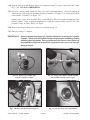
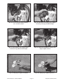
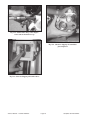
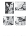
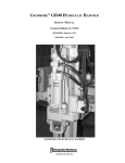
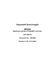
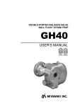
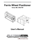
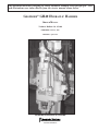
This document describes charging the GH40 Hydraulic Hammer with nitrogen gas. Text
and illustrations were taken directly from the service manual shown below.
GEOPROBE® GH40 HYDRAULIC HAMMER
SERVICE MANUAL
Technical Bulletin No. 95-040
PREPARED: February, 1995
REVISED: April, 2002
GEOPROBE GH40 HYDRAULIC HAMMER
A DIVISION OF KEJR, INC.
COPYRIGHT© 2002, 2000, 1995 Kejr, Inc.
ALL RIGHTS RESERVED
No part of this publication may be reproducedor transmitted in any form or by any means,
electronic or mechanical, including photocopy, recording,or any information storage
and retrieval system, without permission in writing from Kejr, Inc.
WARRANTY: Geoprobe® Systems warrants its products to be free from defects in materials and workmanship under
normal use and service for a period of one hundred eighty (180) days from the date of delivery to the client. Geoprobe
Systems will repair or replace any product returned to Salina, Kansas, which appears upon inspection by Geoprobe
Systems to be defective in materials or workmanship. Geoprobe Systems shall have no obligation under this warranty
for the cost of labor, down-time, transportation charges, or for repair or replacement of any product which has been
misused, carelessly handled or modified or altered.
All other warranties of every kind, whether expressed or implied, including but not limited to any implied warranty
of merchantability or of fitness for a particular purpose and all claims for consequential damages, are specifically
disclaimed and excluded.
Geoprobe® Systems is a Division of Kejr, Inc. located at 601 North Broadway in Salina, Kansas, 67401. Telephone
1-800-436-7762, 785-825-1842 / Fax 785-825-2097.
Geoprobe® and Geoprobe® Systems are registered trademarks of Kejr, Inc. in Salina, KS.
7.0 RECHARGING NITROGEN IN GH-40 HAMMER
Should the Geoprobe® operator experience inconsistency with the percussion function of the GH-40
Hammer, one possible culprit could be a lack of nitrogen charge in the hammer member accumulator chamber.
The percussion function may lack snap or completely fail as a result of inadequate nitrogen charge. Though
hammer failure due to a lack of nitrogen is rare, recharging the hammer member will eliminate the possibility
that an inadequate nitrogen charge is contributing to hammer member failure.
NOTE:
The following recharge procedure requires the use of a cylinder of industrial quality nitrogen
gas, a pressure regulator assembly (Fig 7.1), and a charge valve adapter (Fig 7.2) These are
included in the GH-40 Nitrogen Charge Kit (FA3100K) available from Geoprobe Systems.
7.1
Fold the probe derrick into the vertical position, lower the foot onto the ground, and raise the hammer
to approximately waist level. Shut off the power unit engine.
7.2
Remove the cap from the nitrogen charge port using a 1-3/8" wrench or socket as shown in Figure 7.3.
This will provide access to the nitrogen charge valve shown in Figure 7.4.
7.3
Loosen the lock nut on the nitrogen charge valve by turning it counterclockwise one complete
revolution with a 5/8" socket (Fig. 7.5)
7.4
Thread the large hex cap of the charge valve adapter into the nitrogen port on the hammer (Fig 7.6).
Install the adapter finger tight but with sufficient torque to seat the O-ring within the port.
7.5
Thread the center stem of the charge valve adapter in toward the hammer until it is finger tight. (Fig 7.7).
7.6
Attach the quick-connect coupler on the end of the nitrogen fill hose to the quick-connect nipple on the
charge valve adapter as shown in Figure 7.8.
7.7
Ensure that the line pressure in the nitrogen fill hose is set at zero by turning the regulator tee-handle (Fig
7.9) counterclockwise until it turns freely.
7.8
Open the main valve on the nitrogen cylinder (Fig 7.10) by turning the handle counterclockwise.
7.9
Slowly turn the regulator tee-handle (Fig 7.9) clockwise until the line pressure gauge reads 650 psi.
IMPORTANT:
DO NOT overcharge the system. Charging the system beyond 650 psi will rupture the
accumulator diaphragm or otherwise damage the hammer.
7.10 Close the main valve on the nitrogen gas cylinder (Fig 7.10) by turning the handle clockwise.
7.11 Unthread the charge valve adapter center stem several revolutions out from the hex cap (Fig. 7.11)
7.12 Rotate the regulator tee handle (Fig 7.9) counterclockwise until the line pressure gauge reads 650 psi
(pressure is releaved).
7.13 Remove the charge valve adapter from the hammer by unthreading the large hex cap. Detach the adapter
from the nitrogen fill hose at the quick-connect fittings.
Service Manual – Hammer Member
Page 20
Geoprobe GH-40 Hammer
7.14 Snug the lock nut on the nitrogen charge valve (loosened in Step 7.3) using a rachet and a 5/8" socket
(Fig. 7.20). DO NOT OVERTIGHTEN.
7.15 Listen for a hissing sound around the charge valve and accumulator housing. Check for dripping oil
around the base plate and piston if hammer member is removed as in Figure 7.12, or from the hex drive
if the hammer is installed as in Figure 7.13.
Obvious leaks, such as those described above, would indicate a defective accumulator diaphragm in the
hammer member. If the accumulator diaphragm has failed, the hammer member must be sent to the
Geoprobe factory in Salina, Kansas, for repair.
7.16 Reinstall the nitrogen charge port cap that was removed in Step 7.2.
7.17 Nitrogen recharge is complete.
IMPORTANT: Do not transport the nitrogen gas cylinder without first removing the regulator
assembly. Always secure the cylinder during transport to prevent shifting or rolling
while the vehicle is in motion. These are important safety issures as the cylinder can
be propelled at a high rate of speed if the regulator or valve were to be damaged
during transport.
Fig. 7.1. Nitrogen gas cylinder with
pressure regulator assembly.
Fig. 7.2. Charge valve adapter (left) shown with
nitrogen fill hose quick-connect coupler.
Fig. 7.3. Remove cap from nitrogen charge port.
Fig. 7.4. Nitrogen charge valve and lock nut.
Service Manual – Hammer Member
Page 21
Geoprobe GH-40 Hammer
Fig. 7.5. Loosen lock nut on nitrogen charge
valve one full revolution.
Fig. 7.6. Thread hex cap of charge valve adapter
into nitrogen charge port until hand tight.
Fig. 7.7. Thread charge valve adapter center
seam into hex cap until stem is hand tight.
Fig. 7.8. Attach nitrogen fill hose to charge valve
adapter at quick-connects.
Fig. 7.9. Nitrogen gas regulator tee-handle
Fig. 7.10. Nitrogen gas cylinder main valve.
Service Manual – Hammer Member
Page 22
Geoprobe GH-40 Hammer
Fig. 7.11. Unthread the charge valve adapter
center stem out from the hex cap.
Fig. 7.12. Check for dripping oil around base
plate and piston.
Fig. 7.13. Check for dripping oil from hex drive.
Service Manual – Hammer Member
Page 23
Geoprobe GH-40 Hammer