1
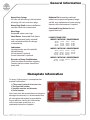
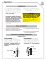
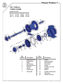
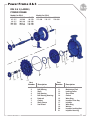
DIN STANDARD
HORIZONTAL
END SUCTION CENTRIFUGAL PUMP SERIES
Installation,Operation and
Maintenance Manual
Table of Contents
Operating and Service Manual for
DIN END SUCTION CENTRIFUGAL PUMP SERIES
FOREWORD ...................................................... 3
GENERAL INFORMATION ................................... 4
RECEIVING AND INSPECTION ............................... 5
INSTALLATION .................................................. 6-7
OPERATION ..................................................... 8-9
DRAWINGS
DIN 1 POWER FRAME ........................... 10
DIN 2 -3 POWER FRAME ......................... 11
PACKING SEAL ......................................12
CARTRIDGE SEAL ...................................12
CLOSED COUPLED STYLE ........................13
CDM STYLE ...........................................13
MALFUNCTIONS / CAUSES...................................14
SPARE PARTS RECOMMENDATIONS........................14
PUMP TIPS .........................................................15
This manual is for a reference guide only. Pumps are built in many variable configurations
and with different options.
Please consult with the factory for more information regarding your individual product.
2
Forward
Operating and Service Manual for
DIN END SUCTION CENTRIFUGAL PUMP SERIES
The design, craftsmanship and materials used in Gusher Pumps provides for optimum performance
and long, trouble-free service. As with any mechanical device, proper use and periodic maintenance will
enhance the performance and life of your pump. This manual is provided as a guideline
for proper installation, operation and maintenance.
THIS MANUAL MUST BE READ AND UNDERSTOOD BEFORE INSTALLING AND OPERATING ANY PUMP.
Supervision by an authorized Gusher representative is recommended to insure proper installation.
!
This operating and maintenance manual contains important notices and warnings.
Please read carefully before installation, electrical connection and initiation.
Further instructions concerning the components of the pump must be observed.
WARRANTY
Gusher Pumps, Inc. will replace or repair at our discretion, within one year of shipment from our plant,
any pump in our judgement that has failed due to defects in materials or workmanship, provided the pump has been
properly installed and maintained and has not been subjected to abuse. These pumps must be returned to
Gusher Pumps, Inc. with complete history of service for inspection and warranty consideration. Gusher Pumps, Inc.
does not accept the responsibility for transportation to and from our plant. Furthermore, we do not assume any
responsibility for consequential damage or loss of production.
Warranty is only valid if genuine Gusher parts are used.
CONTACT GUSHER: 22 Ruthman Drive, Dry Ridge, Kentucky, USA 41035 PH: 859-824-5001 FAX: 859-824-3011
www.gusher.com
3
General Information
Heavy-Duty Casings
All sizes are self-venting with centerline
discharge. All sizes have drain plugs.
Heavy-Duty Shaft-minimum deflection
increases life for less maintenance.
Wear Rings
Renewable carbon wear rings.
Shaft Sleeve - Renewable Shaft Sleeve
eases maintenance (easily removed)
and is releaved to allow for changes
in temperature.
Lubrication:
Standard pumps are with sealed for
life ball bearings.
Oil Lubrication is optional
Grease Lubrication is optional
Direction of Pump Shaft Rotation:
Clockwise when viewed from coupling.
Counter clockwise when viewed from
pump inlet.
Rabbeted Fits-Accurately machined
rabbets ensure positive alignment, longer
seal life, easy replacement of spare rotating
element when maintenance is required.
Contained Casing Gasket-Protects
against blow-out.
3 POWER FRAME SIZES:
MODELS WITH DIN 1 POWER FRAME
32-125
40-125
50-125
65-125
32-160
40-160
50-160
65-160
32-200
40-200
50-200
65-200
32-250
40-250
50-250
80-160
MODELS WITH DIN 2 POWER FRAME
40-315 50-315 65-250
80-200 80-250 80-215
100-200 100-250 100-315
100-250 150-200 150-250
65-315
100-160
125-200
MODELS WITH DIN 3 POWER FRAME
80-400
150-315
100-400 125-315
150-400
125-400
Nameplate Information
On every Gusher pump is a nameplate that
provides information:
1) The pump’s hydraulic characteristics
2) Pump model number
3) Impeller number and diameter
4) Serial number
Since over time, these nameplates can become
damaged or removed, it is recommended that
all name plate information be recorded for
future reference. Having this information
will insure proper spare parts or a
replacement pump are supplied.
4
Receiving and Inspection
Gusher Pumps, Inc. has taken great care
in preparing your pump for shipment,
However, due to circumstances beyond
our control, your shipment may be
received damaged. Therefore we
strongly recommend you take a few
minutes to check your pump upon receipt.
Check for cracked, bent, severely
misaligned (minor misalignments almost
always occur during shipment), or even
missing parts. If any such damage has
occurred, you must report it to the
delivering carrier and Gusher Pumps, Inc.
immediately.
We also recommend that you check the
model number, horsepower, current
characteristics, g.p.m., and ft. head of
the pump received to insure that you have
received the pump you ordered for your
specific operating conditions. if you
should find some discrepancy, report it to
Gusher at once.
Storage
If your pump is not going to be installed
within six months, several precautions
must be taken:
4. Pump suction and discharge points must
be covered to prevent foreign material
from getting into the pump and causing
damage while the pump is started at a
later date.
3. Pumps must be stored in a dry location.
4. Rotate pump shaft several times every
other month.
Handling
! WARNING !
Pump and components are heavy.
Serious physical injury or damage to
equipment should occur from failure
to properly lift and support pump.
Steel-toed shoes must be worn at
all times.
Use care when moving pumps. Lifting
equipment must be able to sufficiently
support the entire pump. Refer to Figs.
2a, b, c for proper lifting techniques.
FIG. 2a
1. Preservative treatment of bearings and
machined surfaces is required.
(Not required for sealed for life
ball bearings).
2. Remove packing on pumps with
stuffing box. The stuffing box
and shaft sleeve must be oil lubricated
to also protect against moisture.
FIG. 2b
FIG. 2c
3. Units equipped with mechanical seals
must also be lubricated with an oil
can through the NPT port while rotating
the shaft by hand.
5
Installation
PREPARATION
When preparing your pump for
installation, the discharge and suction
ports must be clean and free of anything
that might prohibit a tight connection.
This is especially important on the
suction. Air leaks can cause a pump to
operate poorly or to lose prime
completely.
If your pump has been taken out of
storage, all the grease, oil or
preservative must be removed from the ball
bearing housing. The bearing housing must
then be thoroughly cleaned with kerosene
or carbon tetrachloride and relubricated.
This is not required on sealed for life bearings.
On packed pumps, it will be necessary to
clean the shaft sleeve and stuffing box
with kerosene or carbon tetrachloride and
then repack.
LOCATION / FOUNDATION
Whenever possible, locate the pump far
enough below the minimum liquid level
in the resevoir so there will be a positive
head on the suction at all times. Where
this is not possible, the pump should be
located as near to the source of supply as
possible. Allow ample room for inspection
and maintenance.
The foundation should be of heavy
construction to reduce vibration and must
be rigid enough to resist the torque it may
be subjected to.
LEVEL BASEPLATE
Customers mount the bases in a variety
ways. Grouted, welded to other steel, bolted
to concrete floor, etc.
It should be noted at this time that SPECIAL
CARE must be taken when leveling your
pump base for coupling alignment, This is of
the utmost importance. Once the base is in
place and before securing the base, the
coupling alignment should be verified.
The coupling alignment should be checked
again once the base mounting is finished.
After the base is mounted, the only way to
adjust the coupling alignment is by adding
or removing shims underneath the motor feet.
Level baseplate to within 0.125” over the
length and to within 0.062” over the
width by adjusting the wedges.
COUPLING ALIGNMENT
! WARNING !
Before starting any alignment
procedure, ensure that the motor
power is locked out. Failute to do this
will result in serious physical injury.
For trouble-free operation of this unit,
proper alignment must be attained.
Proper alignment is the responsibility of
the installer and user of this pump.
6
Coupling alignment should be checked and
verified:
1) Base installed but not secured
2) Base in place and secured
3) After connecting the system piping
4) Before start-up of a system
Review page 9 for coupling alignment
specifications.
Installation
SYSTEM PIPING
Guidelines for piping are given in the
“Hydraulic Institute Standards” available
from the Hydraulic Institute, 30200 Detroit
Road, Cleveland, OH 44145-1967.
These guidelines should be followed
to ensure proper pump operation.
! WARNING !
Never force piping into position by
pulling it place with the pump suction
and discharge flange bolts.
This will cause misalignment between
pump and driver which will adversely
affect the operation of the unit,
resulting in physical injury and
damage to the equipment.
1). All piping must be supported independently
of the pump.
2). Before connecting the piping to the pump,
ensure that the base is secured.
3). Clean all pipe parts prior to installation.
Suction Piping
! WARNING !
NPSHA must always exceed NPSHR as
shown on Gusher performance curves.
Reference Hydraulic Institute for NPSH
and pipe friction values needed to
evaluate suction piping.
Properly installed suction piping is
necessary for trouble-free pump
operation. Flush suction piping before
connection to the pump.
4). Liquid coming back into the resevoir
should not enter near the pump suction
pipe and the liquid should not drop
from a high level.
5). An isolation valve should be installed in
the suction pipe at least 4 pipe diameters
from the suction to allow closing of the
line for pump inspection and
maintenance.
6). Pipe should be free of air pockets.
7). Piping should be level or slope
gradually downward from the source.
8). No part of the piping should extend
below pump suction flange.
9). The size of the entrance from the
supply should be one or two sizes
larger than the pipe.
Discharge Piping
1). A gate valve and check valve should
be installed in the discharge line. The
check valve should be installed
between the gate valve and the pump.
This will allow for inspection of
the check valve. The gate valve is
required for priming, flow regulation
and for maintenance of the pump.
The check valve is required to prevent
pump or seal damage from reverse flow
through the pump when the motor is
turned off.
2). If quick closing valves are installed in
the system, cushioning devices should
also be installed to protect the pump
from surges and water hammer.
1). Never place a pipe line elbow in the
horizontal plane directly at the pump
suction. Use a straight pipe four to six
pipe diameters long between the elbow
and the pump suction.
3). A pressure gauge should be installed
in the piping just above the pump
discharge. This gauge should be located
at the pump discharge and before
any valves, elbows or other devices.
2). Use suction pipe one or two sizes
larger than the pump suction, with an
eccentric reducer, sloping slide down,
at the suction flange. Suction piping
should never be smaller than the
pump suction.
Final Piping Check
After all piping connections have been
made to the pump:
3). Never throttle the pump on the suction
side. Always control flow by throttling
on the discharge side of the pump.
1) Rotate the shaft by hand to insure that
there is no binding and all parts are
free.
2) Re-check pump alignment to detect any
pipe strain. If pipe strain exists, correct
piping.
7
Operation
PREPARATION FOR START-UP
Check Rotation
1). Wire the motor according to motor
manufacturers specifications and
according to state and local
regulations.
2). Lock out power to driver.
3). Disconnect motor/pump shaft coupling
to prevent dry operation of the pump
when checking rotation.
! WARNING !
Operating the pump dry will cause
damage to the mechanical seal and
may cause the rotating parts to seize.
4). Make sure everyone is clear.
Jog the motor. Determine if the motor
shaft rotation is correct. Refer to page
4 to determine proper motor shaft
rotation. Correct if necessary.
Couple Pump and Motor
1). Lock out power to motor to prevent
accidental rotation and physical injury.
2). Install and lubricate coupling per
manufacturers instructions
3). Verify coupling alignment.
Review page 9 for coupling alignment
specifications.
4). Install coupling guard.
! WARNING !
Never operate a pump without the
coupling guard properly installed.
Personal injury can occur if pump is
run without coupling guard.
INITIAL STARTING
1). Open all inlet piping valves 100%.
2). Open discharge valve 10-15%
3). Remove vent plug on casing to insure
pump has liquid inside the casing.
4). Review pump nameplate and obtain
the pressure the pump was rated for.
5). If your pump is packed, loosen packing
gland screws to allow free leakage.
Then tighten screws uniformly on
packing gland until leakage is reduced
to approximately 30 drops per minute.
Never tighten packing enough to stop
all leakage as a slIght leakage is required
to lubricate packing and prevent
scoring of shaft sleeve.
6). Start motor and immediately observe
pressure gauges. If discharge
pressure is not quickly attained, stop
the pump and attempt to restart.
If pressure is still not obtained, turn
the pump off and investigate the cause.
7). Open the gate valve in the discharge line
gradually as the motor reaches full speed.
(approximately 5 to 10 seconds).
Adjust valve to obtain the pressure
reading as per the pump nameplate.
8). Check pump for vibration levels,
bearing temperature and excessive
noise. If normal levels are exceeded,
shut down and investigate.
OPERATION
1). Always vary the capacity with gate valve
in the discharge line. Never restrict
intake flow.
8
2). If the specific gravity of liquid being
pumped is greater then originally
assumed or if the rated flow is exceeded,
the motor may overload.
Operation
OPERATION
3). Drain all liquid from inside of the pump
if it will be exposed to freezing conditions
while idle. The conditions could cause
liquid to freeze and damage the pump.
Liquid inside cooling coils, if supplied,
should also be drained.
4). If your pump is packed, final leakage
adjustment will be done with the pump
in operation. Tighten screws uniformly on
packing gland until leakage is reduced to
approximately 30 drops per minute.
Never tighten packing enough to stop
all leakage...a slight leakage is required
to lubricate packing and prevent scoring
of shaft sleeve.
5). To prevent damage from cavitation or
recirculation, always operate pump at or
near rated conditions.
! WARNING !
DO NOT operate pump below minimum
rated flows or with suction or discharge
valves closed. These conditions could
create an explosive hazard due to
vaporization of pumpage and can
quickly lead to pump failure and
physical injury
FINAL ALIGNMENT
1). Run the unit under actual operating
conditions long enough for the pump and
motor to reach operating temperature.
2). Check alignment while unit is still hot.
3). Make any necessary adjustments and
reinstall the coupling guards.
COUPLING ALIGNMENT PROCEDURE
Alignment Criteria
Angular Alignment
Check angular alignment with a
micrometer or caliper. Measure from the
outside of one flange to the outside of the
other flange at intervals around the
periphery of the coupling. DO NOT rotate
the coupling. The difference between the
maximum and the minimum must not
exceed .010”.
Parallel Alignment
Check parallel alignment by placing a
straight edge across the two coupling
flanges and measure the offset at various
points around the periphery of the
coupling. DO NOT rotate the coupling. If
offset exceeds .010”, realign the coupling.
Motor Shaft
Motor Shaft
Angular Misalignment
.010 Parallel
misalignment
Straight edge
Pump Shaft
Pump Shaft
9
Power Frame 1
DIN 1 (SMALL)
POWER FRAME
Models for DIN 1
32-125
40-125
50-125
65-125
32-160
40-160
50-160
65-160
32-200
40-200
50-200
65-200
32-250
40-250
50-250
65-250
8
7
5
4
3
1
2
6
18
17
19
20
16
15
14
12
13
11
10
9
Part
Number
1
2
3
4
5
6
7
8
9
10
Description
Bearing Retainer
Ball Bearing
Shaft
Ball Bearing
Bearing Housing
Pedestal
Gasket
Shaft Sleeve
Seal Gland
Part
Number
10
11
12
13
14
15
16
17
18
19
20
Description
Gasket
Mechanical Seal
Spacer Sleeve
Stem Plate
Gasket
Impeller Drive Key
Impeller
Washer
Impeller Locking Nut
Wear Ring
Impeller Housing
Power Frame 2 & 3
DIN 2 & 3 (LARGE)
POWER FRAME
Models for DIN 3
Models for DIN 2
40-315
65-315
80-315
100-250
125-250
50-315
80-200
100-160
100-315
150-200
80-400
125-400
65-250
80-250
100-200
125-200
150-250
100-400
150-315
7
125-315
150-400
8
5
4
3
2
1
6
6
20
21
18
19
15
16
17
14
11
9
10
12
13
Part
Number
1
2
3
4
5
6
7
8
9
Description
Bearing Retainer
Ball Bearing
Shaft
Ball Bearing
Ball Bearing Housing
Pedestal
Gasket
Shaft Sleeve
Seal Gland
Part
Number
10
11
12
13
14
15
16
17
18
19
20
21
Description
Gasket
Mechanical Seal
Locking Collar
Stem Plate
Gasket
Wear Ring
Impeller Drive Key
Impeller
Wear Ring
Washer
Impeller Locking Nut
Impeller Housing
11
Seal Types
CARTRIDGE MECHANICAL SEAL AND PACKING
1
1
2
2
CARTRIDGE TYPE
Mechanical Seal Pump
Number Description:
1...Cartridge Seal
2...Gasket
3
PACKING PUMP
Number Description:
1...Packing Gland
2...Packing
3...Packing Seat Washer
For all other parts descriptions, refer to pages 10 and 11
This illustration is for reference only. Your product may vary. Please consult
with Gusher Pumps for any other information you may require.
12
PUMP STYLE
1
CLOSED COUPLED STYLE
3
Number Description:
4
2
6
5
7
8
9
1...Motor with Shaft
2...Gasket
3...Seal Gland
4...Gasket
5...Ball Bearing Housing
6...Mechanical Seal
7...Key
8...Bolt
9...Washer
1
2
3
CDM STYLE
Number Description:
1...Motor
2...Barrel
3...Coupling
For all other parts descriptions, refer to pages 10 and 11
This illustration is for reference only. Your product may vary. Please consult
with Gusher Pumps for any other information you may require.
13
Troubleshooting and Spare Parts
MALFUNCTIONS / CAUSES
Pump not filled, tubing not deaired
Speed too low
Speed too high
Suction line leaky
Air or gas lock in the pumping medium
Counterpressure too high
Suction head too high
Feed pressure too low with hot pumping medium
Tubing on suction side not sufficiently covered with liquid
Density of pumping medium too high
Viscosity of pumping medium too high
Impeller obstructed
Tubing on suction side obstructed
Wrong rotation
Split rings worn out
Impeller damaged
Driving motor defective
Voltage too low
Frequency too low
Running on 2 phases
Installation / foundation unstable
Motor - pump not well aligned
Bearing worn out
Balance error in the impeller
Impeller too small
x
x
x
x
x
x
x
x
x
x
x
x
x
x
x
x
x
x
x
x
x
x
x
x
x
x
x
x
x
x
x
x
x
x
x
x
x
x
x
x
x
x
x
x
x
x
x
x
x
x
x
x
SPARE PARTS
Gusher recommends that the following spare parts be kept in stock to
decrease the customer’s down time...
14
Cavitation
(Noise
Development)
x
Motor
Becomes Hot
x
Vibrations
x
x
Pumping
Output Stops
After Start
Pressure
Build-Up
Too Little
Cause
Pumping
Output
Too Little
No Pumping
Output
Malfunction
1). Impeller
7). Packing (if applicable)
2). Wear Rings
8). Shaft
3). Ball Bearings
9). Impeller Drive Key
4). Shaft Sleeve
10). Impeller Retaining Washer
5). All necessary gaskets
11). Impeller Retaining Nut
6). Mechanical seal (if applicable)
12). Coupling Insert
x
x
x
x
x
x
Pump Tips
.
COUPLING GUARDS
Never operate a pump without coupling
guards properly installed.
.
.
.
.
.
.
.
.
CONNECTIONS
Never force piping to make connection
with a pump.
Use only fasteners of proper size and
material.
Ensure there are no missing fasteners.
Beware of corroded or loose fasteners.
LUBRICATION
Standard pumps are with sealed for
life ball bearings.
.
.
.
.
.
.
MAINTENANCE SAFETY
Never apply heat to remove impeller.
.
.
.
Grease lubrication is optional.
OPERATION
Never operate below minimum rated
flow or eith suction/discharge valves
closed.
Do not open vent or drain valves, or
remove plugs while the system is
pressurized.
Pump should not be allowed to operate
in a dry mode. This will cause damage
to mechanical seals, packing and other
pump parts.
Ensure pump is isolated from the
system and pressure is relieved before
disassembling pump, removing plugs
or disconnecting piping.
Use proper lifting and supporting
equipment to prevent serious injury.
MECHANICAL SEALS
Must always have liquid for lubrication.
Oil lubrication is optional.
If lubrication information is required,
consult the factory.
Always lockout power.
Double type mechanical seals must have
an external supply source of liquid. This
external liquid must be circulated through
the seal chamber at a pressure equal to or
greater than the pump discharge pressure
at all times.
.
PACKING
Packing must be allowed to leak. This
leakage is the lubrication between the
packing and the shaft / sleeve.
.
SHAFT END PLAY
Maximum pump shaft end play is
0.031”
.
STOPPING / STARTING CYCLES
Maximum start / stop cycles per hour
is 6. Consult the factory if more cycles
are required
CONTACT GUSHER: 22 Ruthman Drive, Dry Ridge, Kentucky, USA 41035 PH: 859-824-5001 FAX: 859-824-3011
www.gusher.com
15
www.gusher.com
Midwest Service Center
Additional
Ruthman Company
Partners:
Superior Engineered Systems
1850 N. Carpenter Rd
Titusville, FL 32796
Phone: 321-747-0733
Fax: 321-747-0529
Web: www.superiorengineeredsystems.com
Ruthman Companies
Worldwide:
Gusher Pumps, Shanghai
ROOM 4012,
Polar Star Business Plaza
No. 913 Changlin Road,
Shanghai, China 200443
Phone: 86-021-26616611
FAX: 86-021-26328038
上海市长临路913号 北斗星广场 4012
室 邮编:200443
电话:86-021-26616611
传真:86-021-26328038
Email: [email protected]
China Mobile: 13402145203
USA Mobile: 513-607-4449
Ruthman Companies
Corporate Headquarters
Incorporating Beresford Pumps
ruthmancompanies.com