1
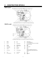
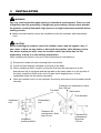
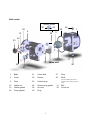
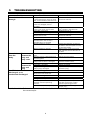
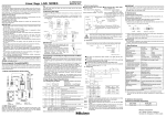
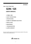
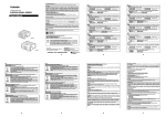
DOUBLE-PORTED BALANCE-VALVE
BALL FLOAT STEAM TRAP
GH40
USER'S MANUAL
SAFETY
WARNING
The MIYAWAKI GH40 is a cast steel ball float steam trap with an integrated
bimetal automatic air vent (GH40D: Diaphragm type).
In order to get maximum benefit from this product, be sure to read this manual
before installing it.
The following warnings and cautions are shown at appropriate
places in this manual.
WARNING
CAUTION
Failure to observe this type of precaution may lead
to serious injury or death.
Failure to follow this type of precaution can lead to
injury or damage to equipment and property.
Table of Contents
1.
SPECIFICATIONS AND MARKINGS
1
2.
CONSTRUCTION DETAILS
2
3.
INSTALLATION
3
4.
MAINTENANCE
4
5.
TROUBLESHOOTING
8
6.
WARRANTY
9
1
SPECIFICATIONS AND MARKINGS
WARNING
Be sure not to use this product at higher pressures than the specified maximum
allowable pressure (PMA) or at temperatures higher than the specified maximum
allowable temperature (TMA).
The following items are displayed on the nameplate or the side of the product.
Check each item to avoid misuse of the product.
(1) Maximum allowable pressure (PMA): 4.0 MPa (580 psig) @100°C (212°F)
(2) Maximum allowable temperature (TMA): 400°C (752°F) @2.7 MPa (329 psig)
(3) Maximum operating pressure (PMO):
GH40-2F/GH40D-2F: 0.2 MPa (29 psig)
GH40-6F/GH40D-6F: 0.6 MPa (87 psig)
GH40-10F/GH40D-10F: 1.0 MPa (145 psig)
GH40-21F/GH40D-21F: 2.1 MPa (305 psig)
(4) Maximum operating temperature (TMO):
GH40 : 400°C (752°F) , GH40D : 220°C (428°F)
(5) Size: 40mm (1-1/2"), 50mm (2")
(6) Serial number: Showing the year and date of production
(7) Flow direction: Shown by an arrow.
(8) Body material: Cast Steel SCPH2
Refer to the leaflet for details about dimensions and other specifications.
1
2
CONSTRUCTION DETAILS
GH40 model
GH40D model
1. 2. Body Cover 12. 13. Pin Pin 23. 24. 3. Float 14. Holder bolt 25. 4. 5. 6. 7. 8. Lever Holder Valve seat Valve seat Valve 15. 16. 17. 18. 19. Holder nut Holder gasket Shaft Split pin U‐nut 26. 27. 28. 29. 30. 9. Lever nut 20. Cover gasket 10. 11. Bolt Spring washer 21. 22. Cover bolt Screen 31. 32. 33. 2
Screen plug Screen plug gasket Air vent (GH40: Bimetal type, GH40D: Diaphragm type)
Plug Plug Name plate Rivet Bush (Only for GH40D model which is equipped with a diaphragm type air vent.)
Bolt Cover nut Collar 3
INSTALLATION
WARNING
Pay very careful attention when working in hazardous environments. There is a risk
of explosion and the possibility of dangerous gases leaking. Always check whether
the pipeline contains flammable, high pressure or high temperature materials before
starting to work.
z Make sure that isolation valves are installed on both the upstream and downstream
lines.
CAUTION
Before installing the product, open both isolation valves and the bypass valve, if
one exists, to blow out any debris or dirt inside the pipeline. After blowing out the
line, before starting to work, close the isolation valves and allow time for the
temperature to drop to a safe working temperature.
When installing the product, be sure to leave clearance for maintaining it.
(1) Remove the dustproof seals covering both connections.
(2) Check the flow direction indicated on the side of the body.
(3) When installing a GH40, install it so that the flow from the upstream line to the
downstream line is horizontal and the top label or the name plate is on the top side of
the body. Install the GH40 at the end of a pipe that is angling down, so that
condensate flows into the steam trap easily.
z Open the isolation valve on the upstream line slowly and make sure the product works
normally.
Clearance for maintenance: More
than 100 mm
Top label
Name plate
Flow direction
Upstream
line
Downstream
line
Clearance for
maintenance: More
than 50 mm
Installation
profile (position)
3
Clearance for
maintenance:
More than
150 mm
4
MAINTENANCE
CAUTION
z
When replacing parts, make sure the replacement parts are supplied by
Miyawaki.
The performance of steam traps deteriorates gradually over time due to wear, corrosion or
dirt accumulating around the valve seat. To keep steam control systems and equipment
working well, periodic maintenance of steam traps is essential.
4.1
Tools for Testing Steam Traps
In order to test steam traps, ultrasonic testers, sound detectors, and thermometers have
been used for years. These tools are relatively easy to use and are useful for making
rough estimates of the level of deterioration of a trap. However, to determine deterioration
levels and steam losses quantitatively, special tools for testing steam traps are required.
Dr. Trap and Dr. Trap Jr. are testing equipment that was developed specifically for
diagnosing steam traps and analyzing survey results automatically. Use these tools to
avoid tiresome jobs on site and save working time.
4.2
Working Conditions of a Steam Trap
Steam trap failures can be classified as either 'Leaking' or 'Plugged'. The level of a steam
leak is generally determined by the intensity of the ultrasonic vibration generated in the
valve seat inside of a steam trap. Plugging is diagnosed by measuring the surface
temperature. As plugging progresses due to a buildup of dirt in the trap, it finally becomes
completely plugged. Then the surface temperature will drop to around 40 degrees
centigrade, or lower.
4
4.3
Repairs
When a trap fails, it is necessary to clean the internal parts and to replace damaged parts.
Take the failed trap apart following the steps below.
4.3.1 Disassembling the trap
1) Loosen the 4 cover bolts (21) and 2
cover nuts (32), and remove the body
(1).
2) The bolt hole makes a convex area
(marked two positions: Arrow and
dashed line) inside the body. Therefore,
you must remove the body (1) carefully
so that the internal unit is not damaged.
3) Lower or raise the body (1) a little, and
then remove it so that the float (3) does
not contact the convex area surrounding
the bolt hole inside the body (1).
4) The internal unit is secured to the cover
(2). Remove the four nuts (15), and then
remove the valve unit connected to the
float (3).
5) Secure the lever (4) with a wrench or
similar device and rotate the float (3) by
hand to remove it.
4.3.2 Disassembling the air vent
1) Remove the body (1), the same as described in the procedure for “Disassembling the
trap” above.
4.3.3 Disassembling the screen
1) Remove the screen plug (23).
2) Remove the screen (22) from the cover (2).
Take the appropriate measures, as described in Section 6, “Troubleshooting”.
Reassemble the parts as follows, reversing the procedure used to disassemble them.
Refer to the torque table to learn the correct torque for each part.
5
4.3.4 Reassembling the screen
1) Attach the screen (22) to the screen plug (23).
2) Attach the screen plug gasket (24), and fit the screen plug (23) into the cover (2) and
tighten it.
Now, be careful to store the tip of the screen pointing into the place where it fits into
the body.
4.3.5 Reassembling the air vent
1) Secure the air vent (25) on the cover (2). (Only for GH40 model)
2) Secure the bush (30) in the air vent (25) on the cover (2). (Only for GH40D model)
4.3.6 Reassembling the trap
1) Connect the float (3) to the valve unit.
2) Attach the holder gasket (16) to the valve unit holder (5).
3) Secure the valve unit to the cover (2). In this case, make sure that the holder gasket is
fitted in the right place. Tighten it with the four holder nuts (15).
z
Make sure to tighten the nuts in a crosswise pattern, to avoid uneven tightening.
4) Attach the cover gasket (20) to the cover (2) and attach them to the body (1).
When reassembling the trap, attach the body carefully so that the internal unit is not
damaged, noting the convex area created by the bolt hole inside the body.
Make sure that the gasket is installed in the right place.
Tighten the body (1) with the 4 cover bolts (21) and cover nuts (32).
z
Finally, tighten the bolts in a crosswise pattern to avoid uneven tightening.
The torque for each part is shown in the following table.
Parts
Models
Tools
Cover bolt (21)
GH40/GH40D
Torque wrench
Holder nut (15)
GH40/GH40D
Torque wrench
Air vent (25)
GH40
Spanner (Wrench)
Screen plug (23)
GH40/GH40D
Torque wrench
Bush (30)
GH40D
Spanner (Wrench)
Cover nut (32)
GH40/GH40D
Torque wrench
6
Across the flats
24 mm
(0.94 in.)
13 mm
(0.51 in.)
32 mm
(1.26 in.)
50 mm
(1.97 in.)
32mm
(1.26 in.)
24mm
(0.94 in.)
Torque
100N-m
(1000kgf-cm)
20N-m
(200kgf-cm)
130N-m
(1300kgf-cm)
300N-m
(3000kgf-cm)
130N-m
(1300kgf-cm)
100N-m
(1000kgf-cm)
GH40 model
GH40D model
30
22
25
2
25
21
20
26
1
3
24
23
15
16
32
31
Valve unit
26
27
1.
Body
21.
Cover bolt
27.
Plug
2.
Cover
22.
Screen
30.
Bush
(Only for GH40D model which is 3.
Float
23.
Screen plug
equipped with a diaphragm type air vent.) 15.
Holder nut
24.
Screen plug gasket
31.
Bolt
16.
Holder gasket
25.
Air vent
32.
Cover nut
20.
Cover gasket
26.
Plug
7
5
TROUBLESHOOTING
Problem
Steam leaks or blows
through.
Possible cause
Foreign material such as scale or dirt is stuck between the valve, the valve seat, and the holder of the valve unit.
The valve, the valve seat and/or the holder are damaged, worn or corroded. The threads on the valve seat or holder in the valve unit are loose.
The holder nut is loose.
The holder gasket is damaged.
Foreign material such as scale or dirt stuck on the air vent.
The air vent is loose.
The seating surfaces on the valve or the valve seat in the air vent is damaged, worn or corroded
Wrong installation position
Wrong installation direction
Steam leaks
from the
body.
From
between the
body and
body cover
From
between the
body and
plug
Insufficient condensate
discharged, or no
condensate discharged.
*1, *2, *3 and *4:
The cover bolts or cover nuts are loose.
Damage, erosion or deterioration of the cover gasket
The gasket sealing surface on the
body or bottom cover is damaged.
The plug is loose.
The gasket is damaged.
The gasket sealing surface on the body or plug is damaged. The screen is clogged.
Foreign material such as a scale or dirt is stuck in the valve seat.
The float is damaged.
The air vent is damaged.
Wrong installation position
The steam pressure was over the
specified maximum operating pressure.
Insufficient condensate capacity.
Solution
Disassemble the valve unit and remove the material. Replace the valve unit. Retighten the threads on the valve seat or holder in the valve unit.
Retighten the nut.*1 Replace the holder gasket.
Disassemble the air vent unit and remove the material. Retighten the air vent or the bush.*2
Replace the air vent. Change the installation so that the top label or the name plate is on the top side of the body. Make sure the arrow on the main
body matches the flow direction of the fluid. Retighten them.*3 Replace the cover gasket. Replace the body with a new one, or replace the bottom cover.
Retighten the plug.*4 Replace the gasket. Replace the body with a new one, or replace the plug. Clean the screen. Clean the valve seat. Replace the float. Replace the air vent. Correct the installation position.
Lower the pressure or replace the
trap with one that has a higher maximum operating pressure.
Replace the trap with a larger
capacity trap. Refer to the torque table in Section 4, “Maintenance” to retighten the parts with
the correct torque.
8
6
WARRANTY
6.1 Warranty period
The warranty period shall last 12 months from the date of product delivery.
6.2 Details of the warranty
If the product stops working correctly within the warranty period, we will repair or
replace the product free of charge if the cause of the trouble is not one of the
following items.
1)
The precautions described in this manual were not observed.
2)
User's errors or mistakes such as an inappropriate installation or incorrect handling,
or an excessively large impact caused by dropping
3)
Problems caused by devices or equipment other than ours, or a disallowed use
environment
4)
When a repair or modification has been performed by anyone other than us or people
who are authorized to make such repairs
5)
Intrusion of salt or other substances that promote significant rust or corrosion or
problems from fluids that contain the same substances
6)
Extremely worn packing, gaskets, or other parts
7)
Attachment or accumulation of foreign objects in the pipe, such as dust and scale
8)
Problems from fires, natural disasters, or other force majeure which is not our
responsibility
6.3 Warranty limitation
The remedy available under the warranty shall not exceed the sales price of the products
delivered, for any cause whatsoever.
9
z お買い上げの製品及びこの取扱説明書内容についてのご質問は下記にお問い合わせく
ださい。また、この取扱説明書を紛失したり、汚損により読めなくなった場合は、同
じく下記へご請求ください。
z For any questions about the product that you purchased or about the details in this
user’s manual, please contact the following.
If you lose this user’s manual or can no longer read it due to stains, please make a
request to the following.
z Copyright © 2009 MIYAWAKI INC. All Rights Reserved.
This user’s manual may not be reproduced or copied in whole or in part, without the
written consent of MIYAWAKI INC.
MCSセンター
〒532-0021 大阪市淀川区田川北2-1-30
TEL: 06-6302-5590 FAX: 06-6305-4089
http://japan.miyawaki.net e-mail:[email protected]
INTERNATIONAL SALES DEPT.
2-1-30, TAGAWAKITA, YODOGAWA-KU, OSAKA 532-0021, JAPAN
Tel: +81-6-63025549 Fax: +81-6-63025595
http://www.miyawaki.net e-mail: [email protected]
OM No. G14-01 1012P