1
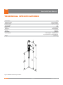
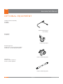
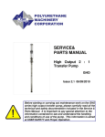
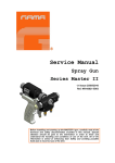
GAMA Deutschland GmbH August-Thyssen-Straße 1 41564 Kaarst Tel. + 49 / 21 31 / 1 76 88 92 Fax + 49 / 21 31 / 1 76 88 93 [email protected] SERVICE & PARTS MANUAL 2:1 Transfer pump GAMA GHO Before starting or carrying out maintenance work on the GAMA GHO series high output transfer pump, please carefully read all the technical and safety documentation included in the Service Manual. It is important to pay special attention to the information contained to see and understand the handling and conditions of use of the pump. This information is aimed at USER SAFETY and the PREVENTION OF PROBLEMS. Service & Parts Manual WARRANTY GARRAF MAQUINARIA, S. A. (hereinafter “GAMA”) provides this LIMITED WARRANTY (hereinafter “Warranty”) to the original purchaser (hereinafter “Customer”) covering this equipment and the original GAMA manufactured accessories delivered with the equipment (hereinafter “Product”) against defects ȋDz dzDz dzȌȋ͙ȌƤ original GAMA invoice (hereinafter “Warranty Period”). If during the Warranty Period under normal use, the Product is suspected by Customer to be Defective in material or workmanship, it is Customer’s responsibility to contact GAMA and return the Product to GAMA as directed by GAMA, freight prepaid. If GAMA determines that the Product is Defective and that such Defect is covered by this Warranty, GAMA will credit Customer for the reasonable freight charges incurred by Customer in returning the Defective Product to GAMA, and GAMA (or its authorized agent) will, at GAMA’s option, repair or replace the Product, subject to the following: Original Invoice: Ƥ Ǥ Ƥǡ Ǥ Product Maintenance: It is the Customer’s responsibility to maintain the Product properly. See your maintenance schedule and owner’s manual for details. The Warranty does not cover an improperly maintained Product. Non-GAMA Components and Accessories: Non-GAMA manufactured components and accessories that are used in the operation of the Product are not Ǥ ơǡǡ such component or accessory. Other Warranty Exclusions: The Warranty does not cover any Product that GAMA determines has been damaged or fails to operate properly due to misuse, negligence, abuse, carelessness, neglect, or accident. By way of example only, this includes: • • • • • • Normal wear an tear. ǡǡǡƤ Ǥ Use of heating devices, pumping equipment, dispensers, or other parts or accessories with the Product that have not been approved or manufac tured by GAMA. Failure to follow the operating instructions and recommendations provided by GAMA. Cosmetic damage. ǡƪǡDz ǡdz Ǥ THE WARRANTY DESCRIBED HEREIN IS THE EXCLUSIVE REMEDY FOR THE CUSTOMER AND IS IN LIEU OF ALL OTHER WARRANTIES, EXPRESS, IMPLIED, STATUTORY OR OTHERWISE, AND THE IMPLIED WARRANTIES OF MERCHANTABILITY AND FITNESS FOR A PARTICULAR PURPOSE AND ALL OTHER WARRANTIES ARE HEREBY DISCLAIMED. TO THE FULLEST EXTENT PERMITTED BY LAW, GAMA SHALL NOT BE RESPONSIBLE, WHETHER BASED IN CONTRACT, TORT (INCLUDING, WITHOUT LIMITATION, NEGLIGENCE), WARRANTY OR ANY OTHER LEGAL OR EQUITABLE GROUNDS, FOR ANY CONSEQUENTIAL, INDIRECT, INCIDENTAL, LOST PROFITS, SPECIAL, PUNITIVE OR EXEMPLARY DAMAGES, WHETHER TO PERSON OR PROPERTY, ARISING FROM OR RELATING TO THE PRODUCT, EVEN IF GAMA HAS BEEN ADVISED OF THE POSSIBILITY OF SUCH LOSSES OR DAMAGES. Non-Warranty Service by GAMA: If GAMA determines that the suspected Defect of the Product is not covered by this Warranty, disposition of the Product will be made pursuant to the terms and conditions of GAMA’s written estimate on a time and materials basis. Continuing Warranty for Products Repaired or Replaced under Warranty: Following the repair or replacement of a Product covered by this Warranty, such Product will continue to be subject to the original Warranty for the remainder of original Warranty Period or for three (3) months from the repair or replacement date, whichever is longer. No Rights Implied: Nothing in the sale, lease or rental of any Product by GAMA shall be construed to grant any right, interest or license in or under any patent, trademark, copyright, trade secret or other proprietary right or material owned by anyone; nor does GAMA encourage the infringement of same. Exclusive Warranty:Ƥǡ ǡ Ǥ ǡ ơơ Ǥǯ ǡ ǡ ǡơ ǡǡ Ƥ ƥ Ǥ 2/16 Issue 2.1 Ref. NR-00018-ENG Service & Parts Manual SAFETY AND HANDLING This chapter contains important information on the safety, handling and use of your GAMA GHO series high output transfer pump. Before installing the GAMA GHO pump and starting it up, carefully read all the technical and safety documentation included in this manual. Pay special attention to the information to know and understand the operation and the conditions of use of the unit. All of the information is aimed at enhancing User Safety and avoiding possible breakdowns derived from the incorrect use of the gun WARNING! establishes information to alert on a situation that might cause serious injuries if the instructions are not followed. PRECAUTION! establishes information that indicates how to avoid damage to the gun or how to avoid a situation that could cause minor injuries. NB: is relevant information on a procedure being carried out. Careful study of this manual will enable the operator to know the characteristics of the pump and the operating procedures. By following the instructions and recommendations contained herein, you will reduce the potential risk of accidents in the installation, use or maintenance of the pump; you will provide a better opportunity for incident-free operation for a longer time, greater output and the possibility of detecting and resolving problems fast and simply. Keep this Service Manual for future consultation of useful information at all times. If you lose this manual, ask for a new copy from your GAMA local distributor or directly contact Garraf Maquinaria, S.A. Important Safety Information The master gun has been designed and built for the application of polyurea chemical systems, polyurethane foam chemical systems and some twocomponent epoxy systems. Always use liquids and solvents that are compatible with the unit. In the event of doubt, consult the GAMA technical service. To prevent possible injury caused by incorrect handling of the raw materials and solvents used in the process, carefully read the safety data sheet provided by your supplier. Deal with the waste caused according to current regulations. ƪǡ nance work on components subject to pressure until the pressure has been completely eliminated. Use suitable protection when operating, maintaining or being present in the area where the equipment is functioning. This includes, but is not limited to, the use of protective goggles, gloves, shoes and safety clothing and breathing equipment. To prevent serious injury through crushing or amputation, do not work with the equipment without the safety guards installed on the moving parts. Make sure that all the safety guards are correctly reinstalled at the end of the repair or maintenance work of the equipment 3/16 Issue 2.1 Ref. NR-00018-ENG Service & Parts Manual TECHNICAL SPECIFICATIONS Pressure Ratio: 2.2:1 Output (Cont. duty): 5.5 gpm (20.8 liters) Output (Int. Duty) 11 gpm (41.6 liters) Cycles per Gallon 18.5 Cycles per liter 4.88 Stroke 4 inch (10.2 cm) Air pressure: 180 psi (0.12 Mpa) Air Inlet: 1/4 NPT (F) Fluid Output: 3/4NPT (F) Air consumption: 2.0 cfm per gallon – pumped @100 psi 124.67 cc/sec per liter – pumped @689 kpa Weight: 25 lbs/11.4 kg 8. (21 34” 2m m) (13 54” 72m m) 36 (93 .75” 3m m) Figure 1 GAMA GHO Transfer Pump Size Shown 4/16 Issue 2.1 Ref. NR-00018-ENG Service & Parts Manual OPTIONAL EQUIPMENT Transfer Pump Air Hose Assembly PU-04000-F PU-04000-H Figure 2 Transfer Pump air Hose Assembly Bung Adaptor PU-04000-33 Figure 3 Bung Adaptor Material Supply Hoses PU-6157A-A-10 3/4 x 10' A Supply Hose (1/2 NPT) PU-6157A-10 3/4 x 10' A Supply Hose (3/4 NPT) Figure 4 Material Supply Hose Swivel Unions PU-179-5 3/4 NPT x 1/2 NPT (F) PU-179-6 3/4 NPT x 3/4NPT (F) Figure 4 Material Supply Hose 5/16 Issue 2.1 Ref. NR-00018-ENG Service & Parts Manual INITIAL MACHINE SET-UP Figure 6 Typical Installation for evloution G-125A 6/16 Issue 2.1 Ref. NR-00018-ENG Service & Parts Manual INSTALLATION On custom installations consult Figure 1 for any dimensions required. 1. Make sure the Gasket (Part No. PU-04000-40) is in place on the threaded end of the Adaptor and screw the Bung Adaptor tightly into the bunghole of the drum. With the second Gasket in place, insert the Transfer Pump through the adaptor, and lock it in place. Figure 11 InstallingTransfer Pump 2. Use thread sealer on the male threads of the Air Needle Valve and Quick Disconnect Plug. Figure 12 Installing Air Needle Vave and Quick Disconnect 3. Use thread sealer on the male Outlet Fitting (not supplied as part of the pump assembly) and ƤǤ Figure 13 Installing Outlet Fitting 4. Install air lines as required. GAMA recommends using a 3/8" ID or larger air line to deliver air to the Transfer Pump. Figure 14 Installing Air Line WARNING! WHENEVER YOU ARE USING, FLAMMABLE MATERIALS ALWAYS CONNECT A GROUND WIRE TO THE PUMP AIR MOTOR. CONSULT THE NATIONAL ELECTRIC CODE, STATE, AND LOCAL CODES FOR ADDITIONAL INFORMATION. 7/16 Issue 2.1 Ref. NR-00018-ENG Service & Parts Manual 5. Connect Ground Wire to the Grounding Lug in accordance with National, State and Local Electric Codes. Figure 15 Installing Ground Wire The Transfer Pump installation is complete. PRECAUTION! THE TRANSFER PUMP INCORPORATES A WET TUBE TO PREVENT BUILD-UP OF CHEMICAL AND DIRT ON THE PUMP SHAFT, WHICH WOULD DAMAGE THE PACKINGS AS THE SHAFT MOVES THROUGH THEM. THE WET TUBE MUST BE FULL WHEN STORING A TRANSFER PUMP OUTSIDE THE PROTECTED ENVIRONMENT OF A SEALED DRUM WITHOUT FIRST THOROUGHLY FLUSHING AND CLEANING THE PUMP. WHEN INSTALLING A TRANSFER PUMP INTO A PARTIALLY FILLED DRUM WHERE THE LIQUID LEVEL IS BELOW THE TOP OF THE WET TUBE, MANUALLY FILL THE TUBE WITH THE PROPER CHEMICAL PRIOR TO INSERTING THE TRANSFER PUMP INTO THE DRUM. IF A DRUM WITH A TRANSFER PUMP INSTALLED TIPS OVER, INSURE THAT THE WET TUBE IS FULL AFTER RIGHTING THE DRUM. THE TRANSFER PUMP PUMPS BOTH RESIN AND ISOCYANATE. TO REDUCE THE POSSIBILITY OF INADVERTENTLY USING THE TRANSFER PUMP WITH THE WRONG CHEMICAL GAMA RECOMMENDS COLOR CODING THE TRANSFER PUMPS RED FOR ISOCYANATE AND BLUE FOR RESIN. 8/16 Issue 2.1 Ref. NR-00018-ENG Service & Parts Manual OPERATION Daily Startup Procedures 1. Determine that the Air Needle Valve is closed. 2. Connect the air line quick disconnect coupler to the Transfer Pump. 3. Turn on the main air supply. 4. Slowly open the Air Needle Valve until the Transfer Pump runs slowly Use the Air Needle Valve to control the pump speed. WARNING! NEVER ALLOW THE PUMP TO RUN DRY OF PUMPING MATERIAL. A DRY PUMP WILL QUICKLY ACCELERATE TO A HIGH SPEED AND POSSIBLY CAUSE PERSONAL INJURY AND/OR DAMAGE THE PUMP. IF THE PUMP ACCELERATES QUICKLY OR STARTS RUNNING TOO FAST, STOP IT IMMEDIATELY AND INSPECT. DO NOT ATTEMPT TO OPERATE THE PUMP WHEN IT IS NOT SECURLY MOUNTED IN A DRUM. KEEP HANDS CLEAR OF THE AREA SHOWN IN FIGURE 16 ALL TIMES AS PERSONAL INJURY MAY OCCUR. Figure 16 Pinch Points Daily Shutdown Procedures 1. Disconnect the air line coupler. ͚Ǥơǡ Ǥ For Extended Period Shutdown Flush, disassemble and thoroughly clean the Transfer Pump before storing in a dry place. MAINTENANCE Introduction WARNING! TO AVOID PERSONAL INJURY, ALWAYS DISCONNECT THE AIR COUPLER AND RELIEVE ALL AIR AND HYDRAULIC PRESSURES BEFORE SERVICING THE PUMP. Before proceeding note the following: *All threads are hand-tight. * When using a repair kit to service the pump use all the parts provided in the kit regardless of the condition of the old ones. This will reduce the possibility of having to rebuild the pump sooner than normal. 9/16 Issue 2.1 Ref. NR-00018-ENG Service & Parts Manual Disassembly 1. Place the Transfer Pump in a vice. Figure 17 Mounting in Vice PRECAUTION! DO NOT CLAMP THE TRANSFER PUMP TIGHTLY NB : It might be necessary to place a strap wrench around the lower end of the suction tube when removing the Foot Valve 2. Remove the Foot Valve housing using a 1 5/8" open-end wrench. Figure 18 Foot Valve NB : Be sure to replace the Bleed Air Plug when reassembling the cylinder. Failure to do so will prevent theTransfer Pump from operating 3. Remove the air bleed from the Transfer Pump Air Cap prior to ơ trapped in the cylinder. The proper procedures are as follows: a) Disconnect the air line to the Transfer Pump b) Open the Air Needle Valve c) Remove the Bleed Air Plug Figure 19 Bleed Air Valve WARNING! THE AIR CYLINDER CONTAINS PRESSURIZED AIR, WHICH MUST BE COMPLETELY EXHAUSTED PRIOR TO DISASSEMBLY. FAILURE TO DO SO MAY CAUSE SERIOUS INJURY TO PERSONNEL AND/OR PROPERTY DAMAGE. 10/16 Issue 2.1 Ref. NR-00018-ENG Service & Parts Manual 4. Place a strap wrench around the lower end of the Air Cylinder and unthread. Figure 20 Strap Location 5. Use a 5/16-inch diameter pin to keep the Piston Rod Plunger from rotating. Unthread the piston. Figure 21 5/16" Diameter Pins 6. Remove the Dowel Pin. Figure 22 Dowel Pin 7. Push the piston out through the suction tube. Figure 23 Removing Piston NB: When replacing the packings pay careful attention to the packing orientation. 8. Inspect and replace the packings as required. Figure 24 Packings 9. Lubricate, install, and assemble parts in reverse order. 11/16 Issue 2.1 Ref. NR-00018-ENG Service & Parts Manual PARTS IDENTIFICATION Transfer Pump Assembly Figure 25 GAMA GHO Transfer Pump Assembly, Exploded View 12/16 Issue 2.1 Ref. NR-00018-ENG Service & Parts Manual Table 1. GAMA GHOTransfer Pump Assembly, Parts Symbol A B C D E F G H J K L M N P Q R S T U V W X Y Z AA AB AC AD AE AF AG AH AJ 13/16 Part Number PU-04000-77 PU-04000-88 PU-04000-78 PU-04000-86 PU-04000-65 PU-04000-83 PU-04000-89 PU-04000-40 PU-04000-87 PU-04000-36 PU-04000-37 PU-04000-64 PU-04000-71 PU-04000-68 PU-04000-63 PU-04000-75 PU-04000-84 PU-04000-79 PU-04000-81 PU-04000-67 PU-04000-91 PU-04000-85 PU-04000-70 PU-04000-69 PU-04000-82 PU-04000-66 PU-04000-24 PU-04000-34 PU-04000-51 PU-04000-61 PU-04000-49 PU-04000-41 PU-04000-53 Description Fiber Washer O-Ring Soket Set Screw Round Head Machine Screw Seal Expander Male Plug Soft Point Set Screw Gasket Socket Head Cap Screw Roll Pin Roll Pin Seal Retainer FE Packing Gasket ơ SuctionTube U-Cup Dowel Pin O-Ring Wave Ring O-Ring Wiper U-Cup Cup Packing Needle Valve Grounding Lug Pump Body (PU-04000 ONLY) Bung Adaper Air Cylinder Mounting Flange Packing Nut Air Cylinder Base Punp Shaft(PU-04000 ONLY) Matl Piston Valve Housing Issue 2.1 Quantity. 1 1 1 1 2 1 1 2 3 2 2 2 4 1 3 1 1 1 2 1 2 2 1 1 1 1 1 1 1 2 1 1 1 Ref. NR-00018-ENG Service & Parts Manual Symbol AK AL AM AN AP AQ AR AS AT AU AV AW AX AY AZ BA 14/16 Part Number PU-04000-55 PU-04000-59 PU-04000-73 PU-04000-80 PU-04000-21 PU-04000-62 PU-04000-57 PU-04000-72 PU-04000-60 PU-04000-17 PU-04000-20 PU-04000-74 PU-04000-01 PU-04000-90 PU-04000-93 PU-04000-92 Description Foot Valve Housing U-Cup Retaining Collar Spring O-Ring Displacement Plunger Air Cylinder Press Relief Screw Compression Spring PlungerTop Air Cylinder Cap (Includes AV) Bumper Bung Adapter Clamp Air Motor Assembly 3/4Dia.SS Ball Snap Ring Snap Ring Issue 2.1 Quantity. 1 1 1 1 1 1 1 1 1 1 1 2 1 2 1 1 Ref. NR-00018-ENG Service & Parts Manual Air Motor Assembly Figure 26 Air Motor Assembly (Part No. PU-04000-01), Exploded View Table 2. Air Motor Assembly, (Part No. PU-04000-01), Parts Symbol A B C D E F G H J K 15/16 Part Number PU-04000-10 PU-04000-14 PU-04000-09 PU-04000-03 PU-04000-08 PU-04000-13 PU-04000-02 PU-04000-15 PU-04000-16 PU-04000-11 Description U-Cup O-Ring Wear Ring Upper Air valve Assembly Spacer Lower Air Valve Socket Head Cap Screw GaskerTop Gasket Bottom Air Piston Issue 2.1 Quantity. 1 1 1 1 3 1 3 1 3 1 Ref. NR-00018-ENG Service & Parts Manual CONTENTS Warranty 2 Safety and handling 3 Ƥ ͞ Optional equipment 7 Initial machine set-up 8 Installation 10 Operation 10 Maintenance 10 Ƥ ͙͘ LIST OF FIGURES Figure 1 GAMA GHO Transfer Pump Size Shown 3 Figure 2. Air Cylinder Assembly, Exploded View 6 Figure 3. Coupling Block Assembly, Exploded View 7 Figure 4. Handle Assembly, Exploded View 8 LIST OF TABLES Table 1. GAMA GHOTransfer Pump Assembly, Parts Table 2. Air Motor Assembly, (Part No. PU-04000-01), Parts GAMA Deutschland GmbH August-Thyssen-Straße 1 41564 Kaarst Tel. + 49 / 21 31 / 1 76 88 92 Fax + 49 / 21 31 / 1 76 88 93 [email protected] 16/16 Issue 2.1 Ref. NR-00018-ENG