1
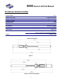
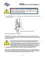
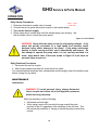
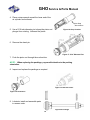
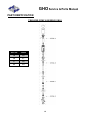
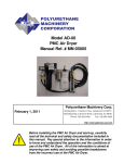
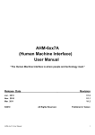
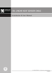
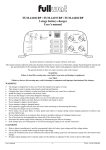
SERVICE& PARTS MANUAL High Output 2 : 1 Transfer Pump GHO Polyurethane Machinery Corp. REVISION 3.0 Headquarters: 1 Komo Drive, Lakewood NJ 08701 Manufacturing: 2 Komo Drive, Lakewood, NJ 08701 Phone:732-415-4400 Fax: 732-364-4025 http://www.polymac-usa.com Before installing the GHO Transfer Pump, carefully read all the technical and safety documentation included in this manual. Pay special attention to the information in order to know and understand the operation and the conditions of use of the GHO Transfer Pump. All of the information is aimed at improving user safety and avoiding possible breakdowns from the incorrect use of the GHO Transfer Pump . GHO Service & Parts Manual Table of Contents WARRANTY.......................................................................................................................... 3 SAFETY AND HANDLING .................................................................................................... 5 TECHNICAL SPECIFICATIONS ........................................................................................... 7 OPTIONAL EQUIPMENT ...................................................................................................... 8 INITIAL MACHINE SET-UP .................................................................................................. 9 INSTALLATION .................................................................................................................. 10 OPERATION ....................................................................................................................... 12 DISASSEMBLY ................................................................................................................... 13 PART IDENTIFICATION ..................................................................................................... 15 TRANSFER PUMP ASSEMBLY (GHO) .......................................................................................... 15 DETAIL A ............................................................................................................................................................................ 16 DETAIL B ............................................................................................................................................................................ 17 DETAIL C ............................................................................................................................................................................ 18 DETAIL D............................................................................................................................................................................ 19 AIR MOTOR ASSEMBLY (PU-04000-01)........................................................................................ 20 AIR MOTOR AND PLUNGER TOP ASSEMBLY (PU-04000-18) ..................................................... 21 AIR MOTOR TO PUMP COUPLING ASSEMBLY (PU-04000-23) ................................................... 22 AIR CYLINDER CAP ASSEMBLY (PU-04000-44)........................................................................... 23 FOOT VALVE ASSEMBLY (PU-04000-45) ..................................................................................... 24 TOOL KIT (PU-04000-94) ............................................................................................................... 25 MANUAL REVISIONS ........................................................................................................ 26 2 GHO Service & Parts Manual WARRANTY Polyurethane Machinery Corporation (hereinafter “PMC”) provides this LIMITED WARRANTY (hereinafter “Warranty”) to the original purchaser (hereinafter “Customer”) covering this equipment and the original PMC manufactured accessories delivered with the equipment (hereinafter “Product”) against defects in material or workmanship of the Product (hereinafter “Defect” or “Defective”) for a period of one (1) year from the date of first purchase as shown on the original PMC invoice (hereinafter “Warranty Period”). If during the Warranty Period under normal use, the Product is suspected by Customer to be Defective in material or workmanship, it is Customer’s responsibility to contact PMC and return the Product to PMC as directed by PMC, freight prepaid. If PMC determines that the Product is Defective and that such Defect is covered by this Warranty, PMC will credit Customer for the reasonable freight charges incurred by Customer in returning the Defective Product to PMC, and PMC (or its authorized agent) will, at PMC’s option, repair or replace the Product, subject to the following: Original Invoice: The original invoice must be kept as proof of the date of first sale and the Product serial number. The Warranty does not cover any Product if the Original Invoice appears to have been modified or altered, or when the serial number on the Product appears to have been altered or defaced. Product Maintenance: It is the Customer’s responsibility to maintain the Product properly. See your maintenance schedule and owner’s manual for details. The Warranty does not cover an improperly maintained Product. Non-PMC Components and Accessories: Non-PMC manufactured components and accessories that are used in the operation of the Product are not covered by this Warranty. Such components and accessories shall be subject to the warranty offered to the Customer, if any, by the original manufacturer of such component or accessory. Other Warranty Exclusions: The Warranty does not cover any Product that PMC determines has been damaged or fails to operate properly due to misuse, negligence, abuse, carelessness, neglect, or accident. By way of example only, this includes: Normal wear and tear. Improper or unauthorized installation, repair, alteration, adjustment or modification of the Product. Use of heating devices, pumping equipment, dispensers, or other parts or accessories with the Product that have not been approved or manufactured by PMC. Failure to follow the operating instructions and recommendations provided by PMC. Cosmetic damage. Fire, flood, “acts of God,” or other contingencies beyond the control of PMC. 3 GHO Service & Parts Manual THE WARRANTY DESCRIBED HEREIN IS THE EXCLUSIVE REMEDY FOR THE CUSTOMER AND IS IN LIEU OF ALL OTHER WARRANTIES, EXPRESS, IMPLIED, STATUTORY OR OTHERWISE, AND THE IMPLIED WARRANTIES OF MERCHANTABILITY AND FITNESS FOR A PARTICULAR PURPOSE AND ALL OTHER WARRANTIES ARE HEREBY DISCLAIMED. TO THE FULLEST EXTENT PERMITTED BY LAW, PMC SHALL NOT BE RESPONSIBLE, WHETHER BASED IN CONTRACT, TORT (INCLUDING, WITHOUT LIMITATION, NEGLIGENCE), WARRANTY OR ANY OTHER LEGAL OR EQUITABLE GROUNDS, FOR ANY CONSEQUENTIAL, INDIRECT, INCIDENTAL, LOST PROFITS, SPECIAL, PUNITIVE OR EXEMPLARY DAMAGES, WHETHER TO PERSON OR PROPERTY, ARISING FROM OR RELATING TO THE PRODUCT, EVEN IF PMC HAS BEEN ADVISED OF THE POSSIBILITY OF SUCH LOSSES OR DAMAGES. Non-Warranty Service by PMC: If PMC determines that the suspected Defect of the Product is not covered by this Warranty, disposition of the Product will be made pursuant to the terms and conditions of PMC’s written estimate on a time and materials basis. Continuing Warranty for Products Repaired or Replaced under Warranty: Following the repair or replacement of a Product covered by this Warranty, such Product will continue to be subject to the original Warranty for the remainder of original Warranty Period or for three (3) months from the repair or replacement date, whichever is longer. No Rights Implied: Nothing in the sale, lease or rental of any Product by PMC shall be construed to grant any right, interest or license in or under any patent, trademark, copyright, trade secret or other proprietary right or material owned by anyone; nor does PMC encourage the infringement of same. Exclusive Warranty: This writing is the final, complete, and exclusive expression of the Warranty covering the Product. Any statements made by PMC, its employees or agents that differ from the terms of this Warranty shall have no effect. It is expressly understood that Customer’s acceptance of this Warranty, by performance or otherwise, is upon and subject solely to the terms and conditions hereof, and any additional or different terms and conditions proposed or expressed by Customer or anyone, whether in writing or otherwise, are null and void unless specifically agreed to in writing by an Officer of PMC. 4 GHO Service & Parts Manual SAFETY AND HANDLING This chapter contains important information on the safety, handling and use of your GHO series high output transfer pump. Before installing the GHO pump and starting it up, carefully read all the technical and safety documentation included in this manual. Pay special attention to the information to know and understand the operation and the conditions of use of the unit. All of the information is aimed at enhancing User Safety and avoiding possible breakdowns derived from the incorrect use of the pump. WARNING! Presents information to alert of a situation that might cause serious injuries if the instructions are not followed. CAUTION! Presents information that indicates how to avoid damage to the Proportioner or how to avoid a situation that could cause minor injuries. NOTE: Is relevant information of a procedure being carried out. Careful study of this manual will enable the operator to know the characteristics of the pump and the operating procedures. By following the instructions and recommendations contained herein, you will reduce the potential risk of accidents in the installation, use or maintenance of the GHO pump; you will provide a better opportunity for incident-free operation for a longer time, greater output and the possibility of detecting and resolving problems fast and simply. Keep this Service Manual for future consultation of useful information at all times. If you lose this manual, ask for a new copy from your PMC Service Center, directly contact Polyurethane Machinery Corporation or on line at our web site (www.polymac-usa.com). 5 GHO Service & Parts Manual IMPORTANT SAFETY INFORMATION The GHO 2:1 pump has been designed and built for the application of polyurea chemical systems, polyurethane foam chemical systems and some two-component epoxy systems. Always use liquids and solvents that are compatible with the unit. In the event of doubt, consult PMC technical service. To prevent possibly injury caused by incorrect handling of the raw materials and solvents used in the process, carefully read the safety data sheet provided by your supplier. Deal with the waste caused according to current regulations. To avoid damage caused by the impact of pressurized fluids, do not open any connection or perform maintenance work on components subject to pressure until the pressure has been completely eliminated. Use suitable protection when operating, maintaining or being present in the area where the equipment is functioning. This includes, but is not limited to, the use of protective goggles, gloves, shoes and safety clothing and breathing equipment. To prevent serious injury through crushing or amputation, do not work with the equipment without the safety guards installed on the moving parts. Make sure that all the safety guards are completely reinstalled at the end of the repair or maintenance work of the equipment. 6 GHO Service & Parts Manual TECHNICAL SPECIFICATIONS Pressure Ratio: 2.2:1 Output (Cont. duty): Output (Int. Duty) Cycles per Gallon Cycles per liter Stroke Air Pressure: Air Inlet: Fluid Output: Air Consumption 5.5 gpm (20.8 liters) 11 gpm (41.6 liters) 18.5 4.88 4 inch (10.2 cm) 180 psi (0.12 Mpa) ¼ NPT (F) ¾ NPT (F) 2.0 cfm per gallon – pumped @ 100 psi 124.67 cc/sec per liter pumped @ 689 kpa 25 lbs/11.4 kg Weight GHO Transfer Pump Figure 1 GHO-S Transfer Pump (Stubby) 7 GHO Service & Parts Manual OPTIONAL EQUIPMENT Figure 2: Transfer Pump Air Hose Assembly PU-04000-F PU-04000-H Figure 3: Bung Adaptor PU-04000-33 Figure 5: Swivel Unions PU-179-5 ¾ NPT x ½ NPT (F) PU-179-6 ¾ NPT x ¾ NPT (F) Figure 4: Material Supply Hose PU-6157A-A-10 ¾ x 10’ A Supply Hose (1/2 NPT) PU-6157A-10 ¾ x 10’ B Supply Hose (3/4 NPT) 8 GHO Service & Parts Manual INITIAL MACHINE SET-UP Figure 6: Typical Installation for Classic Hydraulic Proportioner 9 GHO Service & Parts Manual INSTALLATION On custom installations, consult Figure 1 for any dimensions required. 1. Make sure the Gasket (part No. PU-04000-40) is in place on the threaded end of the adaptor and screw the Bung Adaptor tightly into the bunghole of the drum. With the second gasket in place, insert the Transfer Pump through the adaptor and lock it in place. Figure 7: Installing the Transfer Pump 2. Use thread sealer on the male threads of the Air Valve and Quick Disconnect Plug Figure 8: Installing Air Leedle Valve and Quick Disconnect 3. Use thread sealer on the male outlet fitting (not supplied as part of the pump assembly) and thread the fitting into the outlet port. Figure 9: Installing Outlet Fitting 4. Install air lines as required. PMC recommends using a 3/8” ID or larger air line to deliver air to the transfer pump. Figure 10: Installing Air Line 10 GHO Service & Parts Manual WARNING! Whenever you are using flammable materials, always connect a ground wire to the puma air motor. Consult the Nacional Electric Code, State and Local codes for additional information. 5. Connect ground wire to the Grounding Lug in accordance with National, State and Local Electrical Codes. Figure 11: Installation of Ground Wire The transfer pump installation is complete. PRECAUTION! The transfer pump incorporates a wet tube to prevent build-up of chemical and dirt on the pump shaft, which would damage the packings as the shaft moves through them. The wet tube must be full when storing a transfer pump outside the protected environment of a sealed drum without first thoroughly flushing and cleaning the pump. When installing a transfer pump into a partially filled drum where the liquid level is below the top of the set tube, manually fill the tube with the proper chemical prior to inserting the transfer pump into the drum. If a drum with a transfer pump installed tips over, insure that the wet tube is full after righting the drum. The transfer pump pumps both resin and isocyanate. To reduce the possibility of inadvertently using the transfer pump with the wrong chemical, PMC recommends color coding the transfer pumps red for isocyanate and blue for resin. 11 GHO Service & Parts Manual OPERATION Daily Startup Procedures Keep Clear 1. Determine that the air needle valve is closed. of this area 2. Connect the air line quick disconnect coupler to the transfer pump. 3. Turn on the main air supply. 4. Slowly open the air needle valve until the transfer pump runs slowing. Use the air needle valve to control the pump speed. Figure 12: Pinch Points WARNING! Never allow the pump to run dry of pumping material. A dry pump will quickly accelerate to a high speed and possibly cause personal injury and/or damage to the pump. If the pump accelerates quickly or starts running too fast, stop it immediately and inspect. Do not attempt to operate the pump when it is not securely mounted in a drum. Keep hands clear of the area shown in Figure 16 at all times as personal injury may occur. Daily Shutdown Procedures 1. Disconnect the air line coupler. 2. After the air pressure has bled off, close the air line valve. For extended period shutdown flush, disassemble and thoroughly clean the transfer pump before storing in a dry place. MAINTENANCE Introduction WARNING! To avoid personal injury, always disconnect the air coupler and relieve all air and hydraulic pressures befote servicing the pump. Before proceeding, note the following: All threads are hand tight. When using a repair kit to service the pump use all the parts provided in the kit regardless of the condition of the old ones. This will reduce the possibility of having to rebuild the pump sooner than normal. 12 GHO Service & Parts Manual DISASSEMBLY 1. Place the transfer pump in a vice PRECAUTION: Do not clamp the transfer pump tightly. Hold in Vice by Standoff Figure 13: Mounting in Vice NOTE: It might be necessary to place a strap wrench around the lower end of the suction tube when removing the foot valve. 2. Remove the foot valve housing using a 1 5/8” open-end wrench. NOTE: Be sure to replace the bleed air plug when reassembling the cylinder. Failure to do so will prevent the transfer pump from operating. Figure 14: Foot Valve 3. Remove the air bleed from the transfer pump air cap prior to disassembly of the air cylinder to bleed off any air pressure trapped in the cylinder. a. Disconnect the air line to the transfer pump. b. Open the air needle valve. WARNING! The air cylinder contains pressurized air, which must be completely exhausted prior to disassembly. Failure to do so may cause serious injury to personnel and/or property damage. Figure 15: Bleed Air Valve 13 GHO Service & Parts Manual 4. Place a strap wrench around the lower end of the air cylinder and unthread. Use Strap Wrench Here 5. Use a 5/16-inch diameter pin to keep the piston rod plunger from rotating. Unthread the piston. Figure 16: Strap Location 6. Remove the dowel pin. Figure 17: 5/16” Diameter Pins 7. Push the piston out through the suction tube. NOTE: When replacing the packings, pay careful attention to the packing orientation. 8. Inspect and replace the packings as required. Figure 19: Remove Piston Figure 18: Dowel Pins 9. Lubricate, install and assemble parts in reverse order. Figure 20: Packings 14 GHO Service & Parts Manual PART IDENTIFICATION TRANSFER PUMP ASSEMBLY (GHO) DETAIL A B C D PAGE 16 17 18 19 15 GHO Service & Parts Manual DETAIL A ITEM QTY 1 1 2 1 3 1 4 5 1 1 6 1 24 25 26 27 28 1 1 2 1 1 16 TRANSFER PUMP ASSEMBLY (GHO) PART DESCRIPTION NUMBER AIR CYLINDER CAP ASSEMBLY PU-04000-44 (PAGE 23) PU-04000-62 AIR CYLINDER AIR MOTOR AND PLUNGER TOP PU-04000-18 ASSEMBLY (PAGE 21) PU-04000-79 DOWEL PIN PU-04000-21 DISPLACEMENT PLUNGER AIR MOTOR TO PUMP COUPLING PU-04000-23 ASSEMBLY (PAGE 22) PU-04000-61 PACKING NUT PU-04000-64 SEAL RETAINER PU-04000-71 FE PACKING PU-04000-85 WIPER PU-04000-65 SEAL EXPANDER GHO Service & Parts Manual DETAIL B ITEM 7 8 9 10 11 12 QTY 1 1 1 1 1 2 1 17 TRANSFER PUMP ASSEMBLY (GHO) PART NUMBER DESCRIPTION PU-04000-88 O-RING 2-137 PU-04000-68 PTFE GASKET PU-04000-24 PUMP BODY, GHO PU-04000-26-X STUBBY PUMP BODY PU-04000-50 LOWER COMPRESSION TUBE PU-04000-91 O-RING 2-032 PU-04000-89 #8-32 SOFT TIP SET SCREW GHO Service & Parts Manual DETAIL C ITEM 13 14 15 16 17 18 19 TRANSFER PUMP ASSEMBLY (GHO) QTY PART NUMBER DESCRIPTION 1 PU-04000-59 U-CUP COLLAR 1 PU-04000-69 PISTON CUP 1 PU-04000-41 PUMP SHAFT ASSEMBLY 1 PU-04000-70 U-CUP 1 PU-04000-67 WEAR RING 1 PU-04000-90 3/4" SS BEARING BALL 1 PU-04000-53 PISTON HOUSING 18 GHO Service & Parts Manual DETAIL D ITEM 11 20 21 22 23 19 TRANSFER PUMP ASSEMBLY (GHO) QTY PART NUMBER DESCRIPTION 2 PU-04000-91 O-RING 2-032 1 PU-04000-75 SUCTION TUBE FOOT VALVE ASSEMBLY 1 PU-04000-45 (PAGE 24) 2 PU-04000-40 SQUARE GASKET 1 PU-04000-33 BUNG ADAPTER ASSEMBLY GHO Service & Parts Manual AIR MOTOR ASSEMBLY (PU-04000-01) ITEM 1 2 3 4 5 6 7 8 9 10 11 20 AIR MOTOR ASSEMBLY (PU-04000-01) QTY PART NUMBER DESCRIPTION 1 PU-04000-11 AIR PISTON 1 PU-04000-15 GASKET TOP 1 PU-04000-03 UPPER AIR VALVE ASSEMBLY 3 PU-04000-02 #10-32 X 1-5/16 SHCS 3 PU-04000-08 SPACER 28/32 1 PU-04000-13 WEAWR RING 1 PU-04000-04 SILICONE GASKET 1 PU-04000-09 WEAR RING 1 PU-04000-10 U-CUP 1 PU-04000-14 O-RING 2-018 3 PU-04000-16 GASKET BOTTOM GHO Service & Parts Manual AIR MOTOR AND PLUNGER TOP ASSEMBLY (PU-04000-18) AIR MOTOR AND PLUNGER TOP ASSEMBLY (PU-04000-18) ITEM QTY PART NUMBER DESCRIPTION 1 1 PU-04000-01 AIR MOTOR ASSEMBLY (PAGE 20) 2 1 PU-04000-60 PLUNGER TOP 3 1 PU-04000-78 #10-32 X 3/8 SET SCREW 4 1 PU-04000-80 O-RING 2-223 21 GHO Service & Parts Manual AIR MOTOR TO PUMP COUPLING ASSEMBLY (PU-04000-23) AIR MOTOR TO PUMP COUPLING ASSEMBLY (PU-04000-23) ITEM QTY PART NUMBER DESCRIPTION 1 1 PU-04000-73 SPRING 2 1 PU-04000-81 SQUARE O-RING 3 1 PU-04000-84 U-CUP 4 1 PU-04000-49 AIR CYLINDER BASE 5 3 PU-04000-63 THREADED STANDOFF 6 1 PU-04000-51 AIR CYLINDER MOUNTING FLANGE 7 3 PU-04000-87 1/4-20 X 1 SHCS 22 GHO Service & Parts Manual AIR CYLINDER CAP ASSEMBLY (PU-04000-44) ITEM QTY 1 1 1 1 2 1 3 1 4 1 5 1 AIR CYLINDER CAP ASSEMBLY (PU-04000-44) PART NUMBER DESCRIPTION PU-04000-43 CAP AND BUMPER ASSEMBLY PU-04000-17 AIR CYLINDER CAP PU-04000-20 BUMPER PU-04000-72 SPRING PU-04000-81 SQUARE O-RING PU-04000-77 FIBER WASHER PU-04000-57 #10-32 X 1/2 PRESSURE RELIEF SCREW 23 GHO Service & Parts Manual FOOT VALVE ASSEMBLY (PU-04000-45) ITEM 1 2 3 4 QTY 1 1 1 1 FOOT VALVE ASSEMBLY (PU-04000-45) PART NUMBER DESCRIPTION PU-04000-55 FOOT VALVE HOUSING PU-04000-90 3/4" SS BEARING BALL PU-04000-93 E-RING 5133-75 PU-04000-92 SNAP RING N5000-106 24 GHO Service & Parts Manual TOOL KIT (PU-04000-94) ITEM QTY 1 1 2 1 3 1 4 1 5 2 TOOL KIT (PU-04000-94) PART NUMBER DESCRIPTION PU-04000-82 BALL VALVE PU-04000-83 AIR FITTING PU-04000-86 1/4-20 X 1/2 MACHINE SCREW PU-04000-66 GROUNDING LUG PU-04000-106 SPANNER PIN 25 GHO Service & Parts Manual MANUAL REVISIONS Revision Date Changes Approved 2.5 19-Mar-14 P1 Changed Address to Komo Dr; P16 added air motor drawing to show gasket and 3 washers; updated contents, page and figure numbers to reflect change Vadams 3.0 20-Feb-15 Updated formatting, table of contents, and part description illustrations. Vadams 26