1
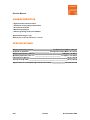
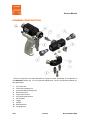
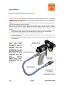
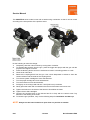
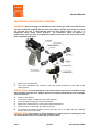
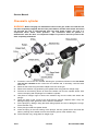
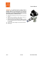
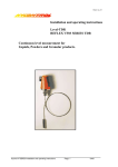
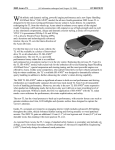
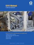
Service Manual
Spray Gun
Series Master II
1.4 Issue 25/05/2010
Ref. NR-00021-ENG
Before installing and starting up the MASTER II gun, carefully read all the
technical and safety documentation included in this manual. Special
attention should be paid to the information in order to know and
understand the handling and conditions of use of the Unit. All of the
information is aimed at enhancing User Safety and avoiding possible
faults due to incorrect use of the Unit.
Service Manual
WARRANTY
GARRAF MAQUINARIA, S. A. (hereinafter “GAMA”) grants this LIMITED WARRANTY to the original
buyer (hereinafter the “Client”) for the unit and the original accessories given with the unit (hereinafter the
“Product”) against any fault in the design, the materials or the manufacture of the Product at the time of the
first purchase by the user and for a duration of two (2) years thereafter.
If during the period of guarantee and under normal conditions of use, the Product should stop working
properly due to faults in the design, the materials or the manufacture, the authorised distributor in the
country where the Product has been purchased or the GAMA technical service will repair or replace the
Product in accordance with what is established in the following
CONDITIONS
a) The validity of this guarantee will be subject to the presentation of the original invoice issued by
the GAMA authorised distributor for the sale of the Product along with the Product handed over
for repair or replacement, which must show the date of purchase and the serial number. GAMA
reserves the right to refuse to give the guarantee service when the indicated data fail to appear
on the invoice or have been modified after the purchase of the Product.
b) The repaired or replaced Product will continue to maintain the original guarantee during the time
remaining until its end, or for three (3) months after the repair date, if the remaining period of the
guarantee were shorter.
c) This guarantee will not be applied to the faults in the Product caused by its faulty installation, the
natural wear and tear of the components, any use other than that considered normal for this
Product or which should fail to strictly comply with the instructions of use provided by GAMA; due
to accident, carelessness, adjustments, alterations or modifications of the Product not authorised
by GAMA or due to the use of accessories, heating devices, pumping equipment and/or
dispensers that have not been approved or manufactured by GAMA.
d) The guarantee applicable to the components and accessories forming part of the Product and
which have not been made by GAMA will be limited to the guarantee offered by the original
manufacturer thereof.
GAMA WILL NOT RECOGNISE ANY EXPRESS ORAL OR WRITTEN GUARANTEES OTHER THAN THIS PRINTED LIMITED
GUARANTEE. ALL IMPLICIT GUARANTEES, INCLUDING, WITHOUT LIMIT, ADAPTATION FOR A SPECIFIC USE, ARE SUBJECT
TO THE DURATION OF THIS WRITTEN GUARANTEE. GAMA DOES NOT ASSUME ANY KIND OF COMMITMENT OR
RESPONSIBILITY FOR ALL POSSIBLE DAMAGE OR EXPENSE CAUSED BY FAULTS IN THE OUTPUT OF THE PRODUCT, ITS
WORKING OR THE DISPENSING OF MATERIAL THROUGH THE PRODUCT, INCLUDING, WITHOUT LIMITATION, ALL
EXPENSES CAUSED BY DAMAGE TO PEOPLE OR PROPERTY. EQUALLY, GAMA WILL IN NO CASE ACCEPT LIABILITY FOR
THE LOSS OF SPECULATIVE PROFITS OR COMMERCIAL LOSSES. ALL REPAIRS OR REPLACEMENT OF FAULTY PRODUCTS
WILL CONSTITUTE THE COMPREHENSIVE FULFILMENT OF GAMA'S OBLIGATIONS WITH RESPECT TO THE CLIENT. GAMA IN
NO WAY GUARANTEES THE IDEALNESS OR SUITABILITY OF ITS PRODUCT FOR ANY PURPOSE OR SPECIFIC APPLICATION.
All of the information provided on components which have not been manufactured by GAMA and which is
based on reports received from the original manufacturer, though considered precise and reliable, is
provided without any guarantee or responsibility of any explicit or implicit kind.
All concession, sale or financial leasing of the Product by GAMA in no case explicitly or implicitly
constitutes any authorisation, acceptance or concession for the use of any rights or patents, nor does it
encourage, nurture or back their infringement.
The restrictions on the guarantee suppose no limitation on the legal rights of the consumer established in
applicable national legislation, nor do they affect any rights derived from the bargain and sale agreement
between the consumer and supplier.
2/21
1.4 Issue
Ref. NR-00021-ENG
Service Manual
All of the information provided in this Service Manual has been included in the confidence that it
is true, although it does not constitute any responsibility or implicit or explicit guarantee. GAMA
reserves the right at any time without forewarning to make all necessary improvements and
modifications to this Service Manual in order to rectify any possible typographical errors,
increase the information contained and enter the changes made to the characteristics and
performances of the gun.
SAFETY AND HANDLING
This chapter contains important information on safety, handling and use of your GAMA
MASTER II series gun.
Before installing and starting up the gun, carefully read all the technical
and safety documentation included in this manual. Special attention
should be paid to the information for knowing and understanding the
handling and conditions of use of the gun. All of the information is aimed
at enhancing User Safety and avoiding possible faults due to incorrect
use of the gun.
A WARNING! establishes information for alerting you on the situations which could
cause serious injury if the instructions are not followed.
A PRECAUTION! establishes information which indicates how to avoid damage to the
gun and how to avoid a situation which could cause minor injuries.
A NOTE is relevant information on the procedure being carried out.
Careful study of this manual will help you to become more acquainted with the gun and the
procedures. Following the instructions and recommendations here will reduce the potential risk
of accidents in installing, using or maintaining the gun, and will give you the problem-free
operation for a longer time, greater output and the possibility of detecting and resolving
problems quickly and simply.
Keep this Service Manual for consultation and useful information at any time. If you lose the
manual, ask for a new copy from your local GAMA distributor or make direct contact with Garraf
Maquinaria, S. A.
WARNING: The gun's design and configuration do not allow it to be used in potentially
explosive atmospheres or to exceed the pressure and temperature limits described in the
technical specifications of this manual.
Always use liquids and solvents that are compatible with the unit. In the event of doubt, consult
the GAMA technical service.
3/21
1.4 Issue
Ref. NR-00021-ENG
Service Manual
When working with the gun, it is essential to dress suitably and use personal protection
equipment, including the unlimited use of gloves, protective goggles, safety footwear and face
masks. Use breathing equipment when working with the gun in enclosed or insufficiently
ventilated atmospheres. The introduction and monitoring of safety measures must not be limited
to those described in this manual. Before starting to use the gun, a rigorous analysis must be
made of the risks derived from the products to be dispensed, the type of application and the
working environment.
The gun forms part of the projection equipment, which is why all safety measures must be taken
that are provided for the start-up use of the equipment, in addition to all specific measures for
the use of the gun.
Carefully read the safety data sheet provided by your supplier to prevent
any possible injury caused by incorrect handling of the raw materials and
solvents used in the process.
Deal with all waste caused according to current regulations.
To prevent serious damage caused by the impact of fluids under
pressure, never open a connection or do maintenance work on
components subject to pressure until you are sure that all pressure has
been eliminated.
Use suitable protection when operating, maintaining or simply being in
the area where the equipment is working. This includes, but is not limited
to, the use of protective goggles, gloves, shoes and safety clothes and
breathing equipment.
The equipment includes components which reach high temperatures and
may cause burns. The hot parts of the unit must not be handled or
touched until they have completely cooled.
To prevent serious injury caused by crushing or amputations, do not work
with the equipment if the safety protections of the moving parts are not
duly installed. Make sure that all safety protections are correctly fitted
after carrying out repair or maintenance work on the equipment
4/21
1.4 Issue
Ref. NR-00021-ENG
Service Manual
CHARACTERISTICS
* High-pressure internal mixture
* Automatic cleaning by pressurised air
* No solvents required
* Mechanical spraying
* Exterior greasing of the mix chamber
Approximate weight: 1 Kg
Dimensions: H 19 cm / W 10 cm / L 19 cm
SPECIFICATIONS
Maximum working pressure: ______________________ 210 Kgf/cm2 (20.6 MPa) / 3000 psi
Required air pressure: ________________________ 6-8 Kgf/cm2 (0.6-0.8 MPa) / 85-114 psi
Maximum production ratio 1:1: _______________________________ 18 Kg/min / 40 lb/min
Minimum production ratio 1:1: ______________________________ 1.5 Kg/min / 3.3 lb/min
Opening force @ 6 bar: ____________________________________________90 Kg / 200 lb
Closing force @ 6 bar: _____________________________________________93 Kg / 205 lb
Approximate air consumption @ 6 bar (50 series/min): _______________ 307 litres/minute
5/21
1.4 Issue
Ref. NR-00021-ENG
Service Manual
GENERAL DESCRIPTION
The main components and their description are given for better knowledge of the elements of
the MASTER II series gun. For more precise identification, see the Components Manual ref.
NR-00020-ENG
1.
2.
3.
4.
5.
6.
7.
8.
9.
10.
11.
6/21
Gun block unit
Polyol side cartridge unit
Isocyanate Side Cartridge Unit
Block Fixture Nut
Polyol manual valve
Isocyanate manual valve
Mix chamber
Trigger
Diffuser
Blocking device
Coupling block
1.4 Issue
Ref. NR-00021-ENG
Service Manual
INSTALLATION AND START-UP
PRECAUTION: When working with the gun or doing maintenance on it, all suitable
protection must be used in accordance with the recommendations and specifications
given by the product suppliers.
GAMA provides a series of tools and accessories which are necessary for assembling the gun.
The unit comprises the following elements:
Metal brush, tube spanner, chuck, pliers for seeger rings, socket, set of Allen keys, tube for
extension of pneumatic connection, grease tube, nozzle stopper, greaser stopper, greasing
pump, air connection pipe, fast plug, tracks for cleaning, operations manual and components
manual.
1. Completely close the manual valves by turning them clockwise. The manual valves control
the input flow of each product to the chamber and are located on the Coupling Block.
2. Connect the air supply pipe to the connector at the rear of the gun.
3. Connect the Isocyanate hose (red terminal) to the Isocyanate input connector (letter A) on
the Coupling Block.
4. Connect the Polyol hose (blue terminal) to the Polyol input connector (letter R) on the
Coupling Block.
NOTE: The product
hoses
have
been
distinguished with red
and blue in order to
allow them to be rapidly
identified.
The
red
corresponds
to
the
Isocyanate hose and the
blue corresponds to the
Polyol hose. To avoid
connection errors, the
Isocyanate and Polyol
hose
coupling
connectors
are
of
different sizes, which
makes it impossible for
connections
to
be
swapped.
7/21
1.4 Issue
Ref. NR-00021-ENG
Service Manual
5.
6.
7.
8.
Open the manual air valve
Pressurise the unit and make sure there are no leaks.
Activate the trigger several times to make sure the mix chamber moves correctly.
Make sure that the pressure in the machine and the temperature of the heaters and the
hoses are correct (see the Machine Service Manual).
9. Completely open the manual valves of each product by turning them anticlockwise.
10. Press the blocking device and turn it anticlockwise to leave it in projection mode or
position.
11. Make a test projection in a vessel
WARNING: Before carrying out maintenance, repair or cleaning work, press the
blocking device and turn it clockwise to leave it in blocking position or mode. Always
remove the coupling block from the gun, completely close the manual product input
valves and disconnect the air supply to avoid any possible accident.
8/21
1.4 Issue
Ref. NR-00021-ENG
Service Manual
This MASTER II series model comes with a head turning mechanism so that it can be turned
according to the inlet position of the product hoses.
Do the following to make the change:
1. Completely close the manual valves by turning them clockwise.
2. To eliminate the pressure from the gun, press the trigger and project with the gun until the
projection fan begins to narrow.
3. Press the blocking device and turn it clockwise to leave it in blocking position or mode
4. Close the air inlet valve.
5. Remove the coupling block from the gun. Use a cloth dampened in solvent to clean the
contact surfaces and the seals of the coupling block.
6. Turn the isocyanate cartridge two turns anticlockwise.
7. Turn the polyol cartridge two turns anticlockwise.
8. Turn the locknut two turns anticlockwise.
9. Pull lightly on the mixing head and turn it 180º (half a turn) clockwise.
10. Gently press the head until it is seated on the throat of the sleeve and cannot turn.
11. Tighten the locknut on the throat of the sleeve to immobilise the head.
12. Tighten the two side cartridges.
13. Connect the coupling block to the mixhead and fix it firmly with the central screw. Pay
attention to the seating of the seals.
14. To leave the gun operative, carry out the following steps for Installation and Start-up.
NOTE: Always turn the head clockwise to pass from one position to another.
9/21
1.4 Issue
Ref. NR-00021-ENG
Service Manual
STANDSTILL METHOD
1.
2.
3.
4.
5.
6.
7.
8.
Perform the Unit Standstill Method with the procedure indicated in the Machine Service
Manual.
Completely close the manual valves of each product by turning them clockwise.
To eliminate the pressure from the gun, press the trigger and project with the gun until the
projection fan begins to narrow.
Press the blocking device and turn it clockwise to leave it in blocking position or mode
Remove the coupling block from the gun. Use a cloth dampened with solvent to clean the
contact surfaces and the seals of the coupling block.
Remove the non-return unit, filter and contact bushing from the polyol side in the mixing
block. Clean the unit with gun cleaning solvent.
Remove the non-return unit, filter and contact bushing from the isocyanate side in the
mixing block. Clean the unit with gun cleaning solvent.
Remove the filter. Carefully clean the filter with gun cleaning solvent, making sure that
there are no remains of product left in the mesh.
PRECAUTION: To avoid spilling the rest of the product which has accumulated in the
side cartridges onto the floor, always remove the coupling block and the side cartridges
on a waste vessel.
9.
Remove the central block by turning the locknut anticlockwise. Clean the block with gun
cleaning solvent.
10. Clean the two contact surfaces of the mix chamber.
PRECAUTION: Use wooden or plastic utensils or a brass brush for cleaning. Do not
use metal utensils, which can scratch the contact surfaces.
11. Fit all the components and put the coupling block in the gun.
12. Remove the stopper and grease the mix chamber with the greasing pump supplied in the
kit with the gun. This will prevent the cleaning air of the gun from drying the ISOCYANATE
product, and will therefore prevent it from crystallising and scratching the chamber and the
bushing. Fit all the components and put the coupling block in the gun.
NOTE: The action of greasing the gun at the end of the day will
avoid maintenance time, as it will not be necessary to dismantle the
chamber each day to clean it.
PRECAUTION: To avoid possible contamination by product
remains on the gun components, do not swap Isocyanate parts with
Polyol parts. The gun has the isocyanate side marked with the letter
A.
If the product hoses still have pressure, follow the Standstill Method
indicated in the Machine Service Manual.
To eliminate the pressure from the hoses with the gun dismantled, put the
product inlet block in a suitable container, remain at a careful distance
and very carefully, very slowly open the manual valves. With pressure, the
product will come out of the top side of the coupling block.
10/21
1.4 Issue
Ref. NR-00021-ENG
Service Manual
MAINTENANCE
To get the most of your MASTER II series gun, periodical maintenance must be carried out.
Carefully read the safety data sheet provided by your supplier to prevent
any possible injury caused by incorrect handling of the raw materials and
solvents used in the process.
Deal with all waste caused according to current regulations.
To prevent serious damage caused by the impact of fluids under
pressure, never open a connection or do maintenance work on
components subject to pressure until you are sure that all pressure has
been eliminated.
Use suitable protection when operating, maintaining or simply being in
the area where the equipment is working. This includes, but is not limited
to, the use of protective goggles, gloves, shoes and safety clothes and
breathing equipment.
The equipment includes components which reach high temperatures and
may cause burns. The hot parts of the unit must not be handled or
touched until they have completely cooled.
To prevent serious injury caused by crushing or amputations, do not work
with the equipment if the moving part safety protections are not duly
installed. Make sure that all safety protections are correctly fitted after
carrying out repair or maintenance work on the equipment
11/21
1.4 Issue
Ref. NR-00021-ENG
Service Manual
Gun block unit and mix chamber
WARNING: Before carrying out maintenance work on the gun, make sure that the unit
has been completely stopped, that all of the push buttons and the main switch are turned
off and that the unit is disconnected from the main power supply. The gun is a
component which works under pressure.
No connection must be opened or
maintenance work be done on component subject to pressure until the pressure has
been completely eliminated.
1.
2.
Remove the coupling block.
Use a cloth dampened with solvent to clean the contact surfaces and the seals of the
coupling block.
PRECAUTION: To avoid spilling the rest of the product which has accumulated in the
side cartridges onto the floor, always remove the coupling block and the side cartridges
on a waste vessel.
3.
4.
5.
6.
7.
8.
Screw on the diffuser.
Turn the isocyanate cartridge two turns anticlockwise.
Turn the polyol cartridge two turns anticlockwise.
Remove the central block by turning the locknut anticlockwise.
Put the block in a vessel with gun cleaning solvent.
To eliminate all product remains, put the gun block unit in a vessel with gun cleaning
solvent and use a brass brush.
PRECAUTION: Use wooden or plastic utensils or a brass brush for cleaning. Do not
use metal utensils which can scratch the contact surfaces.
12/21
1.4 Issue
Ref. NR-00021-ENG
Service Manual
9.
10.
11.
12.
13.
14.
15.
16.
Use a spanner to hold the end of the shaft of the pneumatic cylinder while you unscrew the
mix chamber. Clean the mix chamber and, if necessary, redo the product holes with a drill.
Make sure the chamber is not scratched or marked.
Replace the chamber if it shows any small fault.
Screw the chamber on to the end of the shaft of the pneumatic cylinder.
Fit the gun block unit by sliding it through the chamber and fixing it to the gun with the
fixing nut.
Turn the isocyanate cartridge clockwise until it blocks.
Turn the polyol cartridge clockwise until it blocks.
Fit the coupling block.
Fit the diffuser.
Side cartridge unit
WARNING: Before carrying out maintenance work on the gun, make sure that the unit
has been completely stopped, that all of the push buttons and the main switch are turned
off and that the unit is disconnected from the main power supply. The gun is a
component which works under pressure.
No connection must be opened or
maintenance work be done on components subject to pressure until the pressures have
been completely eliminated.
1.
Perform the Unit Standstill Method with the procedure indicated in the Machine Service
Manual.
2. Completely close the manual valves of each product by turning them clockwise.
3. To eliminate the pressure from the gun, press the trigger and project with the gun until the
projection fan begins to narrow.
4. Disconnect the air supply from the gun.
5. Unscrew the isocyanate side cartridge by turning it anticlockwise and remove it from its
housing. Clean the housing with gun cleaning solvent and make sure no loose particles
remain inside.
6. Remove the filter and clean it with gun cleaning solvent.
7. Make sure the mesh filter is not obstructed. If you see that the mesh is obstructed over
more than 20% of its surface, replace it.
8. Unscrew the rear stopper from the cartridge and use a screwdriver to press the non-return
unit to remove it from its housing, as well as the contact bushing.
9. Clean all of the components meticulously to eliminate all product remains using a cloth
dampened with gun cleaning solvent and a brass brush.
10. Make sure the holes of the filter holder cartridge are not blocked by remains of crystallised
product. If you should see any dirt, clean the communicating drill holes with a drill and a
brass brush.
PRECAUTION! Use wooden or plastic utensils or a brass brush for cleaning. Do not
use metal utensils that can scratch the surface.
Before cleaning the cartridge housing and contact bushing with solvent, remove all of
the o-rings in these components to avoid them being damaged by the solvent or the
brass brush.
13/21
1.4 Issue
Ref. NR-00021-ENG
Service Manual
11. Check the seals of the cartridge and the contact bushing. Replace them if they are worn or
damaged.
12. Check the metal bushing for wear and measure its complete length. Replace it if the length
is under 7 mm.
13. Grease all of the components and refit them in the cartridge.
14. Screw the isocyanate cartridge unit into its housing until it blocks. Make sure it is correctly
tightened to avoid product leaks.
15. Do the same with the polyol cartridge. (points 5-14).
16. Carry out the projection procedure indicated in the start-up section.
17. Start the gun.
PRECAUTION! Use wooden or plastic utensils or a brass brush for cleaning. Do not
use metal utensils, which can scratch the contact surfaces.
14/21
1.4 Issue
Ref. NR-00021-ENG
Service Manual
Trigger and valve
WARNING: Before carrying out maintenance work on the gun, make sure that the unit
has been completely stopped, that all of the push buttons and the main switch are turned
off and that the unit is disconnected from the main power supply. The gun is a
component which works under pressure.
No connection must be opened or
maintenance work be done on components subject to pressure until the pressures have
been completely eliminated.
1.
2.
3.
4.
5.
6.
7.
8.
Remove the coupling block.
Use a cloth dampened with solvent to clean the contact surfaces and the seals of the
coupling block.
Disconnect the air hose supply.
Unscrew the trigger stop bolt.
Remove the retention ring and extract the pin holding the trigger.
Unscrew the nut of the trigger valve.
Remove the trigger shaft and hold it carefully for the end with a few pliers to extract it from
the hole. The trigger shaft has a spring in the base. Make sure you do not lose it.
Check the o-rings of the trigger shaft. Replace them if they are damaged. Apply a little
grease to make assembly easier.
15/21
1.4 Issue
Ref. NR-00021-ENG
Service Manual
9.
10.
11.
12.
13.
14.
15.
16.
Verify that the accommodation of the trigger shaft is free of dirt and wall light a small fat
layer in his interior.
Mount the air hose in the rear part of the gun using sealing paste in the thread to avoid air
escapes.
Insert the trigger shaft in to the spring and insert it inside the handle taking special care not
to damage the o-rings. You will note a certain resistance caused by the interference of the
seals with the housing wall.
Screw down the trigger valve nut until it does ceiling in the fund.
Fit the trigger with the pin and hold it with the retention ring.
Place the trigger stop bolt. It must be tight up to eliminating the roominess of the trigger
shaft (without to displace the shaft).
Fix the mixing block according to the procedure described in the pistol block unit and mix
chamber assembly section.
Start the gun.
16/21
1.4 Issue
Ref. NR-00021-ENG
Service Manual
Cylinder block and blocking device
WARNING: Before carrying out maintenance work on the gun, make sure that the unit
has been completely stopped, that all of the push buttons and the main switch are turned
off and that the unit is disconnected from the main power supply. The gun is a
component which works under pressure.
No connection must be opened or
maintenance work be done on components subject to pressure until the pressures have
been completely eliminated.
1.
2.
3.
4.
5.
6.
7.
8.
9.
Unscrew the screw fixing the sleeve staple on the rear of the gun.
Remove the retention ring positioning the cylinder block, using pliers for seeger rings.
Pull hard on the blocking device to remove the whole unit from the cylinder sleeve. Also
remove the plunger spring.
Check the state of the closing seal of the cylinder block. Replace it if it is damaged.
Apply a little grease to make it easier to assemble.
Loosen the two adjustment screws on the blocking device. Remove the blocking screw and
the blocking spring from the device.
Separate the cylinder block from the blocking screw.
Remove the collar from the cylinder block and replace it if it is damaged. Apply a little
grease to make it easier to assemble.
Pay special attention to correctly fit the collar: the closing lips must be faced towards
the side of the cylinder.
17/21
1.4 Issue
Ref. NR-00021-ENG
Service Manual
10. Fit the cylinder block on the blocking screw. Slip the spring and the blocking device on the
blocking screw. Screw in the two adjustment screws, making sure that they are perfectly
flush with the flats at the end of the blocking screw. Make sure the blocking device is well
fixed.
11. Insert the spring in the rear housing of the plunger. Put the cylinder block unit inside the
sleeve, pressing until it stands out from the insertion groove of the retention ring.
12. Fit the retention ring, using pliers for seeger rings.
WARNING: To guarantee that the cylinder block is
correctly fixed, make sure that the retention ring is
perfectly housed in the fixing groove. To avoid any
possible error in assembly, avoid approaching the
cylinder block when pressure is applied to the gun after
performing any cleaning, repair or maintenance work.
13. Fit the sleeve staple and fix it with the screw to the rear
of the gun.
14. Start the gun.
18/21
1.4 Issue
Ref. NR-00021-ENG
Service Manual
Pneumatic cylinder
WARNING: Before carrying out maintenance work on the gun, make sure that the unit
has been completely stopped, that all of the push buttons and the main switch are turned
off and that the unit is disconnected from the main power supply. The gun is a
component which works under pressure.
No connection must be opened or
maintenance work be done on component subject to pressure until the pressure has
been completely eliminated.
1.
Proceed to remove the mix chamber following the procedure indicated in the Gun block
unit and mix chamber section. Clean the mix chamber and, if necessary, redo the holes
with a drill.
2. Removes the screw fixing the sleeve staple to the rear of the gun.
3. Remove the retention ring positioning the cylinder block using pliers for seeger rings.
4. Pull hard on the blocking device to remove the whole unit from the cylinder sleeve. Also
remove the spring and the plunger from inside the cylinder.
5. Use pliers for seeger rings to remove the retention ring from the shaft, and extract the
plunger.
6. Check the state of the o-rings of the shaft and the plunger. Replace them if they are
damaged. Apply a little grease to make it easier to assemble.
7. Fit the plunger by sliding it along the shaft, taking special care not to damage the o-rings.
Fit the retention ring.
8. Fit the plunger inside the cylinder sleeve.
9. Insert the spring in the rear housing of the plunger. Put the cylinder block unit inside the
sleeve, pressing until it stands out from the insertion groove of the retention ring.
10. Fit the retention ring, using pliers for seeger rings.
19/21
1.4 Issue
Ref. NR-00021-ENG
Service Manual
WARNING: To guarantee that the cylinder block is
correctly fixed, make sure that the retention ring is
perfectly housed in the fixing groove. To avoid any
possible error in assembly, avoid approaching the cylinder
block when pressure is applied to the gun after performing
any cleaning, repairs or maintenance work.
11. Fit the sleeve staple and fix it with the screw to the rear of
the gun.
12. Tighten the mix chamber by hand, using a spanner to
hold the end of the pneumatic cylinder shaft.
13. Fit the gun block unit by sliding it through the chamber
and fix it to the gun with the fixing nut. Make sure you fit
the o-ring between the block and the sleeve, replacing it if
it is damaged.
14. Tighten the two side cartridges. Screw down the diffuser.
15. Start the gun.
20/21
1.4 Issue
Ref. NR-00021-ENG
Service Manual
CONTENT
Warranty ______________________________________________________ 2 Safety and Handling ____________________________________________ 3 Characteristics _________________________________________________ 5 Specifications__________________________________________________ 5 General Description _____________________________________________ 6 Installation and Start-up _________________________________________ 7 Standstill Method ______________________________________________ 10 Maintenance __________________________________________________ 11 Gun block unit and mix chamber _____________________________________________ 12 Side cartridge unit _________________________________________________________ 13 Trigger and valve _________________________________________________________ 15 Cylinder block and blocking device ____________________________________________ 17 Pneumatic cylinder ________________________________________________________ 19 Content ______________________________________________________ 21 21/21
1.4 Issue
Ref. NR-00021-ENG