1
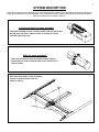
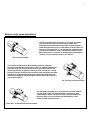
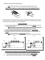
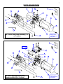
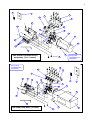
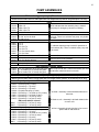
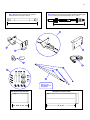
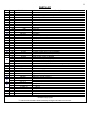
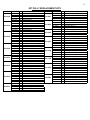
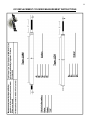
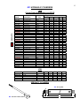
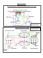
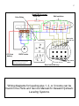
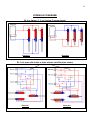
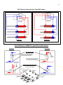
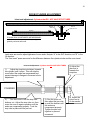
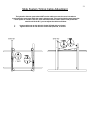
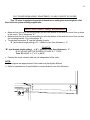
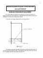
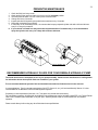
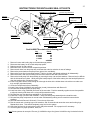
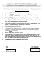
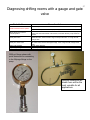
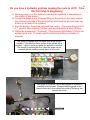
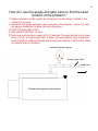
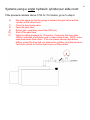
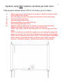
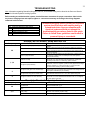
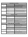
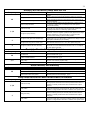
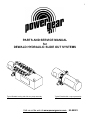
1
PARTS AND SERVICE MANUAL
for
DEWALD HYDRAULIC SLIDE OUT SYSTEMS
Typical Dewald leveling and slide out pump assembly
Typical Dewald slide out pump assembly
Visit us on the web at www.powergearus.com
82-S0523
TABLE OF CONTENTS
Page 3:
WARNING
Page 4:
System description
Page 6:
Manual retraction procedure
Page 7:
Parts breakdowns
Page 10:
Pump assemblies
Page 11:
Parts list
Page14:
Cylinder Identification
Page 16:
Wiring diagrams
Page 18:
Hydraulic diagrams
Page 20:
Room seal and cable adjustment
Page 24:
Preventive maintenance
Page 25:
Instructions for installing seal kit 800176
Page 26:
Diagnosing a cylinder for internal leakage
Page 32:
Troubleshooting
Page 36:
Warranty
2
3
WARNING
• The hydraulic slide-out system is designed as a slide-out
system only. Do not use the Dewald hydraulic slide-out
system for any other reason or function.
• The use of the power gear hydraulic slide-out system to
perform any other function could result in damage to the
coach and/or cause serious injury or even death.
CAUTION - Check that potential parking locations are clear of
obstructions before operation.
CAUTION - Keep people clear of coach while operating the
slide-out system.
CAUTION - Never expose hands or other parts of the body near
hydraulic leaks. High-pressure oil leaks may cut and
penetrate the skin causing serious injury.
CAUTION - Park the coach on a reasonably solid and level
surface to optimize the slide-out system function.
Read, study, and understand the Operations manual for
Dewald slide out systems before operating the slideout
system.
SYSTEM DESCRIPTION
Power Gear manufactures two different styles of the Dewald electro-hydraulic pump assemblies, the leveling and slide out
assembly and the slide only pump assembly. There are different varieties of these styles that will be discussed in greater
detail in the instructions for using the slide out.
Leveling and slide out pump assembly:
This pump assembly is found on motorized RV’s and can actuate four
leveling jacks and up to 3 slide out rooms. It can also be used to
actuate 4 slide rooms, only.
Slide out pump assembly:
This pump assembly is generaly found in towable campers
but may also be used on motorized RVs. It can actuate up to 3
slide out rooms.
Each slide room utilizes a cable and pulley
system to synchronize the room as it
travels in and out.
Cables
Pulleys
Pictures are shown as reference only. Your system and its components may differ slightly from these pictures.
4
5
Slide out only pump assemblies
The BL pump assembly can actuate up to 3 slide out rooms.
Two hoses come from the ports in the top of the pump
assembly and are attached to a hydraulic cylinder mounted
underneath the slide room. On units with 2 or three rooms, the
two hoses from the pump “T” off and then are attached to the
cylinders. One switch is used to extend and retract all rooms.
Most units have two switches for extending and retracting the
room(s), one at the pump and one in the vehicle.
BL 3 & 4 qt. assembly
The selector manifold on the BL assembly allows for individual
extension and retraction of the slide rooms. The manifold assembly on
top of the pump has shut off valves for each room. When shut off, the
valves stop the flow of hydraulic fluid to the slide out cylinder. Turning
the shut off valves clockwise will prevent the room from being extended.
Activation of pump assembly is from one switch. Most units have two
switches for extending and retracting the room(s), one at the pump and
one up in the vehicle.
BL 3 & 4 qt w/ selector manifold
The ESV pump assembly gives you individual, electrical control
over the slide rooms. The system utilizes a mechanical valve
controlled by a 12VDC coil for each slide out room actuated by
the pump. Each room is extended and retracted by it’s own
switch, located inside the coach.
Pump assy. w/ ESV (Electric Solenoid Valve)
Pictures are shown as reference only. Your system and its components may differ slightly from these pictures.
6
MANUAL RETRACTION PROCEDURE
Note: Please read the entire manual before operating this system.
VEHICLES WITH LEVELING + SLIDE ROOMS OR ESV PUMP ASSEMBLIES (Fig 6)
Your Dewald Hydraulic Power System has been designed to operate both the leveling and/or slide out system
from one power source. This power unit has a built-in hand pump for manually retracting the jacks and slide out
room(s) if complete power should be lost to your leveling system.
Hand Pump Operation
1. Turn each of the small slotted setscrews (A) on the front of the pump assembly clockwise until they stop.
This will hold the valves open.
Note: Vehicles that pre-date 2001 may have a red knurled knob on the end of each valve (A). Instead
of turning a setscrew as instructed, you simply pull out the red knobs and turn them a ¼ turn in
either direction. When you release them, they will stay locked in the "out" position.
2. Turn the silver (larger) knurled knob (B) on the front of the power unit 2 turns counter-clockwise.
3. Insert the pump handle into the receptacle (C) and pump the hand pump.
4. When all the jacks and/or the slide out room(s) are fully retracted, tightly close the silver knurled knob
clockwise.
5. Turn each of the small slotted setscrews counter-clockwise, until snug.
Note: If equipped with red knobs (A), turn them a ¼ turn to pop them back into normal operating
position.
Figure 6
Figure 7
VEHICLES WITH OR WITHOUT SELECTOR MANIFOLD PUMP ASSEMBLIES (Fig. 7)
1.
2.
3.
Turn the silver knurled knob (B) on the front of the power unit 2 turns counter-clockwise.
Insert the pump handle into the receptacle (C) and pump the hand pump.
When room(s) are fully retracted, tightly close the silver knurled knob (B) clockwise.
7
PARTS BREAKDOWNS
2
1
22
7
16
5
42
19
4
23
6
3
17
28
27
20
BL 3 and 4 quart pump assembly (1, 2,
or 3 rooms)
See pg. 12 for
part numbers and
descriptions
21
7
3
25 or 26
16
5
6
1
22
24
2
42
19
4
23
3
28
17
27
BL 3 and 4 quart pump assy with
selector manifold (2 or 3 rooms)
20
21
See pg. 12 for
part numbers and
descriptions
8
6
7
14
9
10
8
15
22
24
1
42
19
2
4
23
3
28
18
27
20
ESV (Electric Solenoid Valve)
pump assy. (2 or 3 rooms)
See pg. 12 for
part numbers and
descriptions
21
See pg. 12 for
part numbers and
descriptions
14
10
8
9
22
5
2
11
6
1
7
24
42
19
4
3
23
27
ESV Quad pump assy. (4 rooms)
20
21
28
9
6
See pg. 12 for
part numbers and
descriptions
13
12
14
10
7
22
8
9
2
5
11
1
24
42
19
4
3
23
27
21
Leveling + 1, 2, or 3 slide rooms.
See pg. 12 for
part numbers and
descriptions
20
28
Typical Dewald slide
out configuration.
29 Cable assembly (1 set of cables per room)
31 Cylinder
Pulleys 37
10
PUMP ASSEMBLIES
Slide out only pump assy’s (Round reservoir tanks)
Round reservoir tanks come in 3 and 4 quart sizes. The length of the 3 qt is 8.35” long and 4 qt are 12” long.
PU10141
PU10166
PU12038
PU12781
D4DA
D4DA 3 qt
D4DA 4 qt
D4DA 4 qt w/ T's
D4DA 3 qt w/ T's
D4DA- Indicates that the assembly has no manual
hand pump for emergency retraction of slide(s).
LW
LW- Indicates that the assembly is built with a lead wire
(LW) only. There is no switch at the pump, only inside
the coach.
BL
PU10813 3 qt LW, no switch
PU12525 3 qt LW w/ fuse & diode
PU13638 3 qt LW w/ fuse
PU10437
PU10444
PU11525
PU11526
PU12527
PU12967
BL 3 qt
BL 4 qt
BL 3 qt w/ T's
BL 4 qt w/ T's
BL 3 qt w/ fuse & diode
BL 3 qt w/ fuse
BL- Indicates that the pump is wired for operation at
both locations (BL). There is a switch at the pump and
in the coach.
PU11667 BL 3 qt w/ double selector
PU12157 BL 4 qt w/ double selector
PU12158 BL 4 qt w/ triple selector
BL w/ double selector valves
Has manual valves at the pump that can be opened or
closed to control room operation.
BL w/ triple selector valves
Same as above
ESV (Electric Selector Valve)
PU13222 BL 4 qt w/ triple ESV & 70 amp relay pack
PU13623 BL w/ double ESV & 70 amp relay pack
PU13624 LW w/ double ESV & 70 amp relay pack
ESV- Pump is built with 1 valve/coil assembly per room
for individual, electrical control over each.
Leveling and slide room pump assy’s (Square reservoir tanks)
Square reservoir tanks come in 6 and 8 quart sizes. The length of the 6 qt tank is 12” and the 8 qt is 14” long.
6 quart pump assemblies
PU12463
PU12464
PU12479
PU12598
PU13080
PU13081
PU13631
PU13635
500945
500956
PU13358
PU13632
PU13633
PU13634
PU13636
PU13637
500951
6 qt leveling only (3 valve)
6 qt leveling + 1 (4 valve)
6 qt leveling + 2 (5 valve)
6 qt quad-slide pump (4 valve)
6 qt leveling + 1 w/ diode on coil (4 valve)
6 qt leveling + 2 w/ diode (5 valve)
6 qt leveling + 1 w/ fuse (4 valve)
6 qt leveling + 2 w/ fuse (5 valve)
DMI pumps with PG controls
6 qt leveling + 2 w/ fuse (5 valve)
6 qt leveling + 1 w/ fuse (4 valve)
8 quart pump assemblies
8 qt leveling + 2 w/ diode (5 valve)
8 qt leveling + 1 (4 valve)
8 qt leveling + 1 w/ diode on coil (4 valve)
8 qt leveling + 1 w/ fuse (4 valve)
8 qt leveling + 2 (5 valve)
8 qt leveling + 2 w/ fuse (5 valve)
8 qt leveling + 3 w/ fuse (6 valve)
w/ diode = Assembly is built with diode harness on
solenoids
w/ diode on coil = Assembly is built with diodes inline
on room coils
w/ fuse = Assembly is built with fuse in line on red
power lead for wall switches
11
#30 ** Measure hose from these two points to
determine the hose length in inches.
#29 ** Measure from these two points to determine cable length
in inches. Also note the cable diameter (.25” or .188”).
32
33
35
34
36
30
38
37
16
39
31
See pg. 11 for
part numbers and
descriptions
#28 Round reservoir tank
8.35” or 12”
#28 Square reservoir tank
12” or 14”
12
PARTS LIST
Item Qt y.
1
2
3
4
5
6
7
8
9
10
11
12
13
14
15
16
17
18
19
20
21
22
23
24
25
26
27
28
29
30
31
32
33
34
35
35
35
36
37
38
39
40
41
42
1
1 OK215
*
1 PT
2 WZ1
*
*
*
*
*
1 BA3
1D
1D
*
1
*
*
*
2
2
2
2 VF109
2 VF103
2
1D
1D
1D
1D
1D
1 QA300
1 QA130
1
*
*
*
*
*
*
*
*
*
*
*
*
*
*
*
1 EC10
1D
1
1 80
Part Number
DN11027
00S
DN14866
10000
0000
IP10265 R
IP10260 R
DN13932
DN13933 Ste
DN13937 12
0000
N12649
N12457
DN12494
DN13911
WO11380
IP10400 3
IP10450 6
VF12300
VF10210
VF10100
00
00
VA11000
N11305
N11306
N12560
N12620
N12567
00
00
**
**
See pgs.14 & 15
DN11397
DN13252
DN12148
DN13996
600172
DN13841
DN11879
DN10936
See pg. 12
IP10800
IP10750
IP10810 .75
IP10760 1
024
N11709
600072S
0176
Description
12VDC motor
Pump/motor assembly (pump is not available separately)
Hand pump cartridge valve assembly
Breather cap
12VDC solenoid
ocker switch, white
ocker switch cover, white
P.O. check valve
m valve
VDC coil
Cube relay
Suppression module
Pressure switch
Hose fitting
70 amp waterproof relay pack
90 deg. Hose fitting
-pin pump switch
-pin pump switch
Screw, socket cap, 10-32 x ¼”
Bolt, hex head, ¼ -20 x 1 3/4”
Screw, BHC, 3/8”-16 x ½”
Nut, ¼-20 hex
Lock washer, split
O-ring, black, #016
Faceplate, double selector manifold (2 rooms)
Faceplate, triple selector manifold (3 rooms)
Pump handle
Reservoir tank, square, 12” (6 quart)
Reservoir tank, square, 14” (8 quart)
Reservoir tank, round, 8.75” (3 quart)
Reservoir tank, round, 12” (4 quart)
Synchronization cables (each room has 1 set of sync cables)
Hydraulic hoses
Cylinder
Bracket, mounting, cylinder
Adjustment, horizontal, end condition assy.
Adjustment, vertical, bracket
Adjustment, vertical, bracket 7.0”
Adjustment, vertical, bracket 6.5”
Adjustment, vertical, bracket 6.0”
Wear pad, black 1.0” dia.
Wear pad, white 1.5” dia.
Pulley assembly
.75” nylock nut
1.12” nylock nut
” jam nut
.12” jam nut
24” ball screw electric
Air cylinder
Hand pump assembly
O-ring seal kit (see page 23)
* Quantities vary by system.
** Cable and hose assemblies should be ordered by the length of the cable or hose in inches.
13
#37 PULLY REPLACEMENT KITS
Kit P/N
PL10342
PL10343
PL10344
PL10345
PL10407
PL10413
PL10414
PL10521
BOM
600115
CW10100
SY60913 2
VF11500
VF12060
IP21004
CW10100
DN10661
SY60915
VF11500
VF12060
IP21004
DN10310
DN10280
DN10661
SY60914 4
VF11500
VF12060
IP21004
DN10310
DN10280
DN10661
SY60914 2
VF11500
VF12060
IP21005
IP21105
VF11500
VF12060
600116
CW10100
SY60913 4
SY60914 4
VF11500
VF12060
IP21005
CW10100
IP21105
SY60915
SY60916
VF11500
VF12060
600115
CW10100
SY60913 4
VF11500
VF12060
Qt.
2
2
4
4
2
2
2
2
4
4
2
4
4
2
8
8
2
2
2
2
4
4
6
6
4
4
6
4
8
8
6
4
6
2
2
8
4
2
2
4
4
Description
3" dia. double groove pulley assy
pulley shaft .75 x 3.75
spacer pulley pvc
pin cotter 1/8 x 1
washer flat 3/4
3" dia. double groove pulley
pulley shaft .75 x 3.75
1-1/8" o.d. x 3/4"
3/4" x 1" sleeve
pin cotter 1/8 x 1
washer flat 3/4
3" dia. double groove pulley
pulley shaft .75 x 2.75
pulley mounting br
1-1/8" o.d. x 3/4"
spacer pulley pvc
pin cotter 1/8 x 1
washer flat 3/4
3" dia. double groove pulley
pulley shaft .75 x 2.75
pulley mounting br
1-1/8" o.d. x 3/4"
spacer pulley pvc
pin cotter 1/8 x 1
washer flat 3/4
5.5" dia. single groove pulley
bushing flange 1.1
pin cotter 1/8 x 1
washer flat 3/4
3" dia. single groove pulley assy
pulley shaft .75 x 3.75
spacer pulley pvc
spacer pulley pvc
pin cotter 1/8 x 1
washer flat 3/4
5.5" dia. single groove pulley
pulley shaft .75 x 3.75
bushing flange 1.1
3/4" x 1" sleeve
3/4" x 1-1/2" slee
pin cotter 1/8 x 1
washer flat 3/4
3" dia. double groove pulley assy
pulley shaft .75 x 3.75
spacer pulley pvc
pin cotter 1/8 x 1
washer flat 3/4
Kit P/N
PL10671
PL10672
PL10753
PL10791
PL11090
PL11102
PL12130
IP60080
BOM
IP21004
DN10662
VF11500
VF12060
600115
CW10100
DN10317
VF11500
VF12060
600115
SY60900
VF11500
VF12060
IP21004
DN10661
DN10764
SY60915
VF11500
VF12060
600114
DN10310
DN10317
VF11500
VF12060
600114
CW10100
VF11500
VF12060
600114
CW10100
DN10310
SY60913
VF11500
VF12060
600114
DN10310
DN10317
VF11500
VF12060
Qt.
2
2
2
2
2
2
2
4
4
2
1
2
2
2
2
2
2
2
2
2
2
2
4
4
2
2
4
4
2
1
2
4
4
4
2
2
2
4
4
Description
3" dia. double groove pulley
1-1/8" o.d. x 3/4"
pin cotter 1/8 x 1
washer flat 3/4
3" dia. double groove pulley assy
pulley shaft .75 x 3.75
bracket pulley mtg
pin cotter 1/8 x 1
washer flat 3/4
3" dia. double groove pulley assy
pulley shaft .75" x 6"
pin cotter 1/8 x 1
washer flat 3/4
3" dia. double groove pulley
1-1/8" o.d. x 3/4"
2" channel strap
3/4" x 1" sleeve
pin cotter 1/8 x 1
washer flat 3/4
2.25" dia. double groove pulley assy
pulley shaft .75 x 2.75
bracket pulley mtg
pin cotter 1/8 x 1
washer flat 3/4
2.25" dia. double groove pulley assy
pulley shaft .75 x 3.75
pin cotter 1/8 x
washer flat 3/4
2.25" dia. double groove pulley assy
pulley shaft .75 x 3.75
pulley shaft .75 x 2.75
spacer pulley pvc
pin cotter 1/8 x 1
washer flat 3/4
2.25" dia. double groove pulley assy
pulley shaft .75 x 2.75
bracket pulley mtg
pin cotter 1/8 x 1
washer flat 3/4
14
#31 REPLACEMENT CYLINDER MEASUREMENT INSTRUCTIONS
15
#31 HYDRAULIC CYLINDERS
LWW
Current Production Cylinders are BOLD
Physical Dimensions (inches)
Part #
Description
130-1226
1.5 X 42 non ext
= OBSOLETE
130-1155
130-1156
130-1157
*
130-1159
CW10320
CW10323S
CW10324S
*CW10325S
CW10326S
*CW10327
CW10329
*CW10400
CW10416
*CW10420
*CW10500
*CW10520
CW10524S
*CW10534
*CW10538
*CW10620
Color
1.5 x 24 ext
1.5 x 24 non ext
1.5 x 41 ext
1.5 x 38 ext
2 x 24 non ext
2 x 32 non ext
2 x 32 non ext
2 x 38 non ext
2 x 38 ext
2 x 40 non ext
2 x 48 non ext
2 x 40 (Dutchmen)
1.125 x 16.5 non ext
1.5 x 20 non ext
2 x 44 non ext
1.5 x 20 non ext
1.5 x 24 non ext
1.5 x 34 non ext
1.5 x 38 non ext
1.5 x 20 non ext
Black
Black
Black
Black
Black
Green
Yellow
Yellow
Gray
Gray
Green
Yellow
Black
Black
AB
25.25
25.25
42.25
42.25
25.0
32.75
33.0
39.0
39.0
41.0
49.0
36.75
17.38
23.5
45.0
23.12
27.5
37.12
39.25
23.5
1.75
2.38
2.38
2.38
2.38
2.38
2.38
2.38
2.38
1.38
1.875
2.38
1.75
1.75
1.75
1.38
1.88
18.37
7.0
7.0
7.0
7.0
18.37
7.0
7.0
7
2.75
3.5
7.0
7.25
7.0
7.25
7.0
7.25
.75
.75
.75
.75
.75
.75
.75
.75
.75
.625
.75
.75
.75
.625
.75
.75
.625
41.25
1.75
7.0
.75
CW10638
1.5 x 38 non ext
Purple
39.25
CW10719
1.5 x 19 ext
Blue
20.25
CW10640
CW10720
*CW10724
CW10726
CW10729
CW10732
*CW10738
*CW10741
*CW10820
*CW10824
DN11816
*DN11997S
CW11836
1.5 x 40 non ext
1.5 x 20 non ext
1.5 x 24 non ext
1.5 x 26 ext
1.5 x 29 non ext
1.5 x 32 ext
1.5 x 38 ext
1.5 x 41 ext
1.5 x 20 non ext
1.5 x 24 ext
1.5 x 40 (Dutchmen)
1.5 x 38
Green
Gray
Green
Red
Red
Yellow
Gray
Blue
Purple
Green
Black
Black
D
18.37
6.75
18.37
45.25
Blue
Gray
Gray
Black
C
1.75
1.75
1.75
20.88
25.25
27.25
30.25
33.25
39.25
42.25
20.88
25.25
40.5
41.5
1.75
1.75
1.75
1.75
1.75
1.75
1.75
1.75
1.75
1.75
1.75
1.75
1.75
1.75
7.0
6.75
18.62
7.12
7.0
18.62
4.0
18.62
18.62
18.62
3.5
18.62
3.18
7.0
.75
.75
.75
.75
.75
.75
.75
.75
.75
.75
.75
.75
.75
.75
.75
.75
.625
E
.75
.75
.75
.75
.75
.75
.75
.75
.75
.75
.75
.75
.75
.625
.75
.75
.75
.625
.75
.75
.625
.75
.75
.75
.75
.75
.75
.75
.75
.75
.75
.75
.75
.625
LDH
*CW10120
*CW10140
CW10175S
*CW10200
CW10300S
CW10410
2 x 32
2 x 17
2 x 24
2 x 32
2 x 38
2 x 44
33.0
18.0
25.0
33.0
39.0
45.0
Black
Red
Yellow
Gray
2.38
2.38
2.38
2.38
2.38
2.38
7.0
7.0
7.0
7.0
7.0
7.0
1.12
1.12
1.12
1.12
1.12
1.12
n/a
n/a
n/a
n/a
n/a
n/a
SPECIALTY CYLINDERS
#41- Air cylinder
.5"
#40 - 24” ball screw electric
.5"
24.91"
26.53"
.625"
16
WIRING DIGRAMS
BL 3 and 4 quart, with or without selector manifold, with 1, 2 or 3 rooms
Solenoids
+12V from battery
B
A
Wall Switch
12VDC motor
M
Pump Switch
The green wire sends signal to the
pump to retract rooms. The blue
wire sends signal to extend.
Double or triple ESV (2 or 3 rooms)
70 amp waterproof relay pack
The green wire sends signal to the
pump to retract rooms. The blue
wire sends signal to extend.
Pump switches
Stem valve
and 12V coil
5 amp fuse
M
12VDC motor
+12V from
battery
P.O. check
valve
Wall switches
ESV manifold assy
17
Quad ESV (4 rooms)
5 amp fuse
Cube Relay
Wall switches
B
A
Stem valve
and 12V coil
M
+12V from
battery
12VDC motor
The green wire sends signal to the
pump to retract rooms. The blue
wire sends signal to extend.
Quad manifold assy
P.O. check
valve
Wiring diagrams for leveling plus 1, 2, or 3 rooms can be
found in the Parts and Service Manual for Dewald Hydraulic
Leveling Systems.
18
HYDRAULIC DIAGRAMS
BL 3 or 4 quart – 1, 2, or 3 rooms (3 rooms shown)
Pump assy.
Pump assy.
Retraction
Extension
BL 3 or 4 quart with double or triple selector manifold (triple shown)
Selector manifold
Extension
Retraction
19
ESV (Electric Solenoid Valve) Triple ESV shown
Extension
Retraction
ESV HYDRAULIC SCHEMATIC (triple ESV manifold shown)
Retraction
Extension
P.O. check valve
P.O. check valve is opened during
extension by pressurized fluid from
the extend side of the pump
Retract
hose port
P.O. check valve is opened during
retraction by pressurized fluid from
the retract side of the pump
Return to reservoir
From pump
Extend hose
port
Stem valve and 12vdc coil
Stem valve is opened when 12V coil
is energized with voltage.
From pump
Extend hose
port
PO check
valve
Return to reservoir
Stem valve
and 12V coil
Retract hose
port
20
ROOM CYLINDER ADJUSTMENT
In/out seal adjustment- Cylinders that DO NOT HAVE STOP TUBES
Room floor
Nut pair “A”
Jam nuts
Nut “B”
Nylon jam nut
Cylinder
IF ROOM SEAL ADJUSTMENTS ARE NECESSARY,
start with nuts as far apart as possible, then tighten
gradually until seals are made.
Free travel
Jamb nuts are used to adjust tightness of room seals. Nut pair “A” in the OUT direction; nut “B” in the
IN direction.
The “free travel” space accounts for the difference between the cylinder stroke and the room travel.
In/out seal adjustment- Cylinders that DO HAVE STOP TUBES
1)
Adjust the stop tube clockwise (towards
the cylinder) until it stops. This will stop the
room before the seals are compressed and
prevent damage to flanges in the event of misadjustment.
2) Adjust the
jam nuts in
towards the
stop tube.
CYLINDER
5)
Run the room in until the stop tube
bottoms out. Adjust the stop tube out, then
move the room in again repeating until the
seals are compressed properly. Lock the
stop tube in place with the jam nut.
3) Run the room out,
then adjust the jam nuts
to push the bracket until
the seals are
compressed properly.
Tighten the jam nuts
together to prevent
movement.
4) Adjust the
nylock nut in
to the bracket.
Slide System Timing Cable Adjustment
The hydraulic slide out system does NOT use the cables to move the room, but rather to
synchronize the room travel while the room is being moved. This synchronizing system keeps the
room square as it slides in and out. If the wall of the slide for some reason is not parallel the
outside wall of the R.V, you can adjust the cables as follows:
1.
2.
Loosen cable nuts at side which is further IN (right side, as shown)
Tighten cable nuts at side which is further OUT (left side, as shown
21
22
FLAT FLOOR ROOM HEIGHT ADJUSTMENT---FLUSH FLOOR STYLE SLIDES
This TIP sheet is designed to provide information on setting the room height on a flat
floor slide-out system utilizing angled rails.
•
•
•
With the room fully extended-
Measure from the top of the moving slide-out rail to the bottom of the slide-out room floor up close
to the coach. This is dimension “A”.
Measure from the top of the moving slide-out rail to the bottom of the slide-out room floor out near
the mounting bracket. This is dimension “B”.
To calculate dimension “B” use the following formula:
“B” (end bracket height setting)=“A” + (slideout room floor thickness) + ¼”.
EXAMPLE:
“B” (end bracket height setting) =“A” + (slideout room floor thickness) + ¼”.
If “A” = 3-1/4” AND THE SLIDEOUT FLOOR IS 1” THICK
Then “B”=3-1/4” + 1” + ¼” = 4-1/2”
•
Perform this check on each slide-out rail independent of the other.
NOTE:
1) These figures are approximates. Each coach may be slightly different.
2) Refer to manufacturer of coach/trailer for correct slideout room floor thickness.
23
NON-FLUSH FLOOR TYPE ROOM
ADJUSTMENT
PREVENTIVE MAINTENANCE
24
1.
2.
3.
4.
5.
6.
7.
Check the fluid level every month.
Check and/or fill the reservoir with the room(s) in the fully retracted position.
The fluid should be within 1/2 inch of the top of the reservoir tank.
Change fluid every 24 months.
Inspect and clean all hydraulic pump electrical connections every 12 months.
Keep slide mechanism free of debris.
If rooms are out for extended periods, it is recommended to spray exposed cylinder rods with a silicone lubricant
every 5 to 7 days for protection.
8. If your vehicle is located in a salty environment (within 60 miles of coastal areas), it is recommended to
spray the cylinder rods every 2 to 3 days with a silicone lubricant.
Fill port breather cap
RECOMMENDED HYDRAULIC FLUIDS FOR YOUR DEWALD HYDRAULIC PUMP
The fluids listed here are acceptable to use in your pump assembly. Contact coach manufacturer or selling dealer
for information about what specific fluid was installed in your system.
It is not recommended that hydraulic fluid and automatic transmission fluids be mixed in the reservoir.
In most applications, Type A automatic transmission fluid (ATF, Dexron III, etc.,) will work satisfactorily. Mercon V is also
recommended as an alternative fluid for Dewald hydraulic systems.
If operating in cold temperatures (less than -10° F) the jacks may extend and retract slowly.
For cold weather operation, fluid specially formulated for low temperatures may be desirable. Mobil DTE 11M, Texaco Rando
HDZ-15HVI, Kendall Hyden Glacial Blu, or any Mil. Spec. H5606 hydraulic fluids are recommended for cold weather
operation.
Please consult factory before using any other fluids than those specified here.
25
INSTRUCTIONS FOR INSTALLING SEAL KIT 800176
VA25400 O-rings, black #904
VA1100 O-rings, black #016
DN11027
12VDC motor
VA20000 O-rings, white
VA14350 O-ring, thick
(install this in the groove)
DN14866
Cartridge
valve
OK21500S
pump/motor ass’y
Put rounded side
of washer towards
hand pump
600072S hand pump assy
DN10672 lift tube
Torque to 70 in/lbs.
VA25300 O-ring (install this o-ring
around the edge)
Seal kit 800176 contains the following parts:
1.
2.
3.
4.
5.
6.
7.
8.
9.
10.
11.
12.
13.
14.
15.
16.
17.
18.
19.
20.
21.
Qty.
Part #
2 VA110
00
2 VA143
50
2 VA200
00
1 VA253
00
VA25400
4
Return all rooms and leveling legs to the travel/storage position.
Disconnect the battery for the coach and pump system.
Drain the tank of oil with a siphon.
Mark each hose, and wire for their respective positions.
Remove each hose from the pump assy. and insert the ends into a bucket in case of leakage.
Remove the power leads to the pump motor (green, blue, and black).
Remove the pump from its mounting bracket. Take it to a clean, well-lighted workbench for disassembly.
Remove the tank; drain any remaining fluid and clean inside of tank with a lint free cloth.
Remove the hand pump from the assembly by removing the two nuts and lock-washers. Removal may be difficult
with the inlet strainers in place. While pulling the hand pump off of the hollow tubes, pivot the hand pump down to
clear the strainers after it clears the tubes.
Insert a long Allen wrench small enough to fit through the holes in the hollow tubes to check them to make sure
they are tight (right hand thread).
Clean the components before re-assembly.
Install 2 new o-rings (VA25400) onto each tube (4 total), lubricate them with Dexron III.
Re-install the hand pump onto the pump assy.
Install one white o-ring (VA20000) onto each of the two tubes. Push the assembly together as much as possible
to align the housing and tubes so the o-rings will be seated correctly.
Re-install the nuts onto the tubes and tighten to 70 inch/ pounds.
Install new o-rings (VA14350 and VA25300, 1 each) onto hand pump assembly and re-install the tank.
Re-install the pump components in reverse order of disassembly making sure to match the hose and wire
markings.
Re-fill the tank with Dexron III fluid until ½” from the top of the tank.
Run the rooms and or leveling legs to full extension, wait 30 seconds and retract the rooms and leveling legs.
Repeat this 4 times. This should completely purge air from the system.
Check the fluid level in the tank with all rooms and jacks retracted. Fill to proper level if necessary.
Test the system for proper operation, leaks, etc.
Note: Some systems do not require The two (2) VA25400 o-rings. One(1)extra VA14350 o-ring is included in the kit .
DIAGNOSING A DEWALD CYLINDER FOR INTERNAL LEAKAGE
26
The following test can be used when no gauge / gate valve tool is available. It should be noted
that the gauge will be more accurate and give more definite test results than this method.
The piston seal inside of a hydraulic cylinder can deteriorate over time due to normal wear, contaminated fluid,
etc. If a cylinder is suspected to be leaking internally, then diagnose using the following procedure:
Check only one cylinder at a time.
1:
Completely RETRACT suspected cylinder.
2:
Remove the EXTEND hose at the cylinder. See page 17–18 for hydraulic diagrams to
determine EXTEND and RETRACT hoses.
3:
Push the RETRACT or IN switch for at least 10 seconds and note how much fluid is
coming from the fitting. A small amount to trickle is normal, steady flow is not. The
pump will groan but hold the switch for as long as 10 seconds. If internal piston seal is
good, little to no fluid should be coming out of fitting.
4:
If, at this point, the seal has proven to be faulty, then repair or replace cylinder. If seal
appears to be holding pressure, continue with the diagnosis.
5:
Re-attach the removed EXTEND hose.
6:
Completely EXTEND suspected cylinder. If a vehicle lift is not accessible, it may be
necessary to park the coach over a service pit to get leveling cylinder completely
extended without lifting coach.
7:
Remove the RETRACT hose at the cylinder.
8:
Push the EXTEND or OUT switch for at least 10 seconds and note how much fluid is
coming from the fitting. A small amount to trickle is normal, steady flow is not. The
pump will groan but hold the switch for as long as 10 seconds. If internal piston seal is
good, flow should be greatly reduced or stopped by then.
9:
Do this with each cylinder, to determine a faulty cylinder.
Cap (extend) side of
cylinder
Rod (retract) side of
cylinder
Diagnosing drifting rooms with a gauge and gate
valve
Probable Cause
Leaks somewhere in the system
Stem valves are in manual
override position
Faulty stem valve
Faulty P.O. check valve
Valve coils miswired
Cylinder(s) leaking
Bad o-ring in pump assembly
Corrective Action
Check all hydraulic hoses for visible leaks. Check that all connections are tight.
Diagnose and replace as necessary any faulty cylinder
Turn slotted set screws at the end of the valves counterclockwise until they stop. If
system has red knobs instead of set screws, turn knobs until they “snap” back into
position.
Swap the suspicious valve with one of the other good valves. If the problem
follows the valve, check for bad o-rings on the tip of the valve. If o-rings are OK,
change valve.
Swap the suspicious check valve with a good check valve. If the problem follows
the check valve, check for damaged o-rings. If the o-rings are OK, change check
valve.
Check wiring diagrams.
Replace cylinder or have cylinder resealed
Install o-ring replacement kit #800176.
3000 psi Gauge shown with
quick disconnect for connecting
to the fill/purge fittings on the
pump.
Gauges assembled as
shown here will be the
most versatile for all
applications.
27
28
Do you have a hydraulic problem causing the room to drift? Take
this first Step in diagnosing.
A. Relieve pressure on the system by moving the cylinders to somewhere in
the middle of their stroke.
B. Couple the gauge to the fill /purge fitting on the pump on the same side as
the outlined color side of the decal (retract side-decal on the hose may say
bottom or rod side of the cylinder).
C. Run the pump to retract the jacks with the control. The pump should run for
5-7 seconds after reaching 1400psi, and should achieve at least 2000psi.
D. Watch the pressure for 15 minutes. If the pressure falls below 1750 psi the
system has a leak. The leak could be internal (and thus not visible), or
external.
This gauge is installed onto the retract side of the pump’s
manifold. This will show if any portion of the system has a
problem. It will not show you where the problem is however.
The benefit of checking like this is that the gauge can be
installed without creating a mess, and it is very quick.
This gauge is shown as it would be installed on a pump for
checking a bad cylinder. Always install the gauge on the
hoses hooked up to the outlined color side of the decal, not
the solid color side.
29
How do I use the gauge and gate valve to find the exact
location of the problem?
1) Relieve pressure on the system by moving the cylinder being checked to the
middle of it’s stroke.
2) Assemble the gauge and gate valve as shown in the diagram. Install it so that
the gauge is between the gate valve and the pump.
3) Shut off gauge’s gate valve.
4) Run pump to 2000 psi. or more.
5) Note how much pressure seeps off in 15 minutes. Pressure should not go lower
than 1750 psi. If it goes lower than 1750psi, the pump shuttle valve is bad and
pump should be replaced. Replacement pump part number is OK21500S. (does
not include tank or manifold)
Hydraulic pressure gauge
Gauge’s gate valve
To jack leg
Dewald leveling jacks pump assembly
Systems using a single hydraulic cylinder per slide room:
If the pressure remains above 1750 for 15 minutes, go on to step 6
6)
7)
8)
9)
10)
11)
Move the gauge so that the gauge is between the gate valve and the
cylinder on the retract hose.
Close the hand pump valve.
Open the gate valve.
Retract jack completely (more than 2000 psi).
Shut off the gate valve.
Watch for falling pressure for 15 minutes. If pressure falls more than
200lbs it indicates a bad piston seal or other external leak. NOTE: some
seals leak slower than others. If the room takes several days before
drifting, extend the time that you observe the cylinder retraction pressure.
Test each cylinder to find the exact source of the problem.
To cylinder
30
31
Systems using two hydraulic cylinders per slide room:
If the pressure remains above 1750 for 15 minutes, go on to step 6
6)
7)
8)
9)
10)
11)
12)
Relieve pressure on the system by m oving the cylinder(s) being checked
to the middle of their stroke.
Move the gauge so that it is between the cylinders on the retract hose.
Close the hand pump valve.
Open the gauge’s gate valve.
Retract completely (more than 2000 psi).
Shut off the gauge’s gate valve.
Watch for falling pressure for 15 minutes. If pressure falls more than
200lbs it indicates a bad piston seal or other external leak.
NOTE: The cylinder with the leak will be the one on the gauge side of the
valve.
NOTE: In order to prove that both cylinders are not leaking, the gauge will
have to be moved to the other side of the gate valve and the test repeated.
NOTE: Some seals leak slower than others. If the room takes several days
before drifting, extend the time that you observe the cylinder retraction
pressure. Test each cylinder to find the exact source of the problem.
32
TROUBLESHOOTING
Note: Information regarding Dewald leveling parts, service, and troubleshooting can be found in the Parts and Service
Manual for Dewald Hydraulic Leveling Systems.
Before starting to troubleshoot the system, check all harness connectors for proper connection. Also look for
any loose or hanging wires and replace, tighten or connect as necessary according to the wiring diagrams
contained in this manual.
All
1
2
3
4
Pump assembly key
All pumps discussed in this manual
BL 3 or 4 quart assy.
BL 3 or 4 quart with selector manifold assy.
Double or triple ESV assy.
Quad ESV assy.
Pump assy.
Troubleshooting any Direct Current (DC) electrical
system should be done with caution and by a
trained technician. Anyone unfamiliar with
electrical systems should not attempt the
troubleshooting procedures listed in this guide.
Failure to follow these guidelines could result in
personal injury or even death.
Room(s) will not extend, pump does not run
Probable Cause
Low or no voltage at pump assembly
5 amp fuse blown
All
Bad connection of motor ground wire at pump
Motor or pump has failed
Solenoid “A” faulty
1, 2, 4
No signal to pump assembly
3
No signal to relay pack from wall switch(es)
No signal from relay pack to 12VDC motor
4
Pump assy.
All
3, 4
No signal to solenoid “A” from cube relay
Corrective Action
Verify that the battery is fully charged and connected to the electrical
system.
Check 5 amp in-line fuse at pump assembly. Replace as necessary.
Check grounding of black wire coming directly out of 12VDC motor at
the pump assembly.
Check for continuity between blue and black wires of 12VDC motor. If
no continuity, replace motor. If continuity is found, then replace
pump/motor assembly.
With any room extend switch pushed, small post of solenoid “A” should
show 12V+.If so, then two large posts of solenoid “A” should have
continuity across them. If no continuity, replace solenoid.
Check for 12V+ at the pump assembly on the copper buss bar that ties
solenoids “A” and “B” together. If power is found, jumper the two large
posts on solenoid “A” to see if pump will run. If pump runs then
continue trouble shooting system to isolate problem.
The blue wire from the wall switches to the relay pack should show
voltage when any room extend switch is pressed. If no voltage is found,
then replace wall switch(es) as necessary.
With any wall switch pressed, the lug on the relay pack with the blue
wire attached should show 12V+. If not, then replace relay pack.
With any room extend switch pressed, terminal 87a of cube relay should
show 12V+. If so, then terminal 30 should show 12V+. If no voltage at
30, then replace cube relay.
Room(s) will not extend, pump does run
Probable Cause
Low fluid level
The silver, knurled knob on the hand pump is
open
Faulty coil(s)
Valve coils miswired
Corrective Action
Fill tank to proper level. See Preventive Maintenance and
Recommended Fluids, pg 21.
Knurled knob must be turned clockwise for normal operation.
Check for continuity across the two yellow wires coming out of each of
the coils. If no continuity, replace coil(s).
Check wiring diagrams.
33
Room extends, but erratically
Pump assy.
Probable Cause
Room is out of synchronization
All
Pump assy.
Room seals or rails dry
Lubricate room seals and rails with silicone spray.
Internal leak in slide room cylinder
See “diagnosing a Dewald cylinder for internal leakage” , pg 19.
Pump does not shut off when extend switch is released
Probable Cause
Solenoid “A” faulty
1, 2, 4
Faulty switch
Relay pack faulty
3
Faulty switch
Pump assy.
2, 3, 4
Probable Cause
Faulty selector knob
Cylinders plumbed to manifold incorrectly
Stem valves are in manual override position
3, 4
Coils and/or switches wired incorrectly
Faulty stem valve
Pump assy.
Probable Cause
Air trapped in system
1
Corrective Action
Chose correct selector knob.
Remove selector knob from manifold assembly and inspect the end for
damage or contamination. Swap with a known good valve on manifold.
If symptom swaps, then replace selector knob. If symptom does not
swap, then continue troubleshooting to isolate defective component.
Check plumbing of cylinders (See hydraulic diagrams, pg. 17)
Turn slotted set screws at the end of the valves counterclockwise until
they stop. If system has red knobs instead of set screws, turn knobs
until they “snap” back into position (see pg 6).
Check wiring of coils and switches according to the wiring diagrams
contained in this manual.
Swap suspected stem valve with a known good stem valve on manifold.
If symptom swaps, replace stem valve. If stem valve has red knurled
knob on the end (old style), then valve and coil must be replaced.
Room “creeps” back in once extended
A leak somewhere in system
All
Corrective Action
Remove blue wire from large top post of solenoid “A”. Test across the
two large posts of solenoid “A” for continuity while the extend switch is
pressed. If continuity remains after switch is released, then replace
solenoid.
Remove blue wire from large top post of solenoid “A”. Check for voltage
at small bottom post of solenoid “A” while the extend switch is pressed.
If voltage remains after switch is released, then replace switch.
Remove large blue wire from lug of relay pack. Test across that lug and
the center lug (red wire) for continuity while the extend switch is
pressed. If continuity remains after switch is released, then replace
relay pack
Remove large blue wire from lug of relay pack. Check for voltage at
blue wire in relay pack coming from switches while the extend switch is
pressed. If voltage remains after switch is released, then replace switch.
Wrong room extends
Wrong selector knob chosen
2
Corrective Action
See “cable adjustment”, pg 20.
Bad piston seal in cylinder(s)
Bad o-ring seal between hand pump and pump
assembly
The silver, knurled knob on the hand pump is
open
Bad piston seal in cylinder(s)
Stem valves are in manual override position
3, 4
Faulty stem valve
Corrective Action
Check all hoses, hose connections, pump assembly, etc for any visible
fluid leak. Repair any found leaks as necessary.
Verify that hose connection ports on cylinder are pointing as close to 12
o’clock as possible. Cycle room(s) to complete extension and retraction
allowing system to rest 5 minutes in-between cycles. Do this 4 times.
This should purge the air from the system.
Test for internal cylinder seal leakage per instructions on pg 19.
Install o-ring kit #800176 as per pg 22.
Knurled knob must be turned clockwise for normal operation.
On the BL 4 quart pump assembly where 2 or more rooms are teed
together, a bad cylinder on one room can make another room creep
back in. Be sure to check all cylinders for internal piston seal leakage on
these systems.
Turn slotted set screws at the end of the valves counterclockwise until
they stop. If system has red knobs instead of set screws, turn knobs
until they “snap” back into position (see pg 6).
Swap suspected stem valve with a known good stem valve on manifold.
If symptom swaps, replace stem valve. If stem valve has red knurled
knob on the end (old style), then valve and coil must be replaced.
34
Pump assy.
Room(s) will not retract, pump does not run
Probable Cause
Low or no voltage at pump assembly
5 amp fuse blown
All
Bad connection of motor ground wire at pump
Motor or pump has failed
Solenoid “B” faulty
1, 2, 4
No signal to pump assembly
3
No signal to relay pack from wall switch(es)
No signal from relay pack to 12VDC motor
4
Pump assy.
All
3, 4
No signal to solenoid “B” from cube relay
Probable Cause
Low fluid level
System overfilled with fluid
Faulty coil(s)
Valve coils miswired
Corrective Action
Fill tank to proper level. See Preventive Maintenance and
Recommended Fluids, pg 21.
Drain tank to proper level. See Preventive Maintenance and
Recommended Fluids, pg 21.
Check for continuity across the two yellow wires coming out of each of
the coils. If no continuity, replace coil(s).
Check wiring diagrams.
Room retracts, but erratically
Probable Cause
Room is out of synchronization
Pump assy.
Check grounding of black wire coming directly out of 12VDC motor at
the pump assembly.
Check for continuity between blue and black wires of 12VDC motor. If
no continuity, replace motor. If continuity is found, then replace
pump/motor assembly.
With any room retract switch pushed, small post of solenoid “B” should
show 12V+.If so, then two large posts of solenoid “B” should have
continuity across them. If no continuity, replace solenoid.
Check for 12V+ at the pump assembly on the copper buss bar that ties
solenoids “A” and “B” together. If power is found, jumper the two large
posts on solenoid “B” to see if pump will run. If pump runs then
continue trouble shooting system to isolate problem.
The green wire from the wall switches to the relay pack should show
voltage when any room retract switch is pressed. If no voltage is found,
then replace wall switch(es) as necessary.
With any wall switch pressed, the lug on the relay pack with the green
wire attached should show 12V+. If not, then replace relay pack.
With any room retract switch pressed, terminal 87a of cube relay should
show 12V+. If so, then terminal 30 should show 12V+. If no voltage at
30, then replace cube relay.
Room(s) will not retract, pump does run
Pump assy.
All
Corrective Action
Verify that the battery is fully charged and connected to the electrical
system.
Check 5 amp in-line fuse at pump assembly. Replace as necessary.
Corrective Action
See “cable adjustment”, pg 20.
Room seals or rails dry
Lubricate room seals and rails with silicone spray.
Internal leak in slide room cylinder
Check cylinder for internal piston seal leakage. See “diagnosing a
Dewald cylinder for internal leakage” , pg 19.
Pump does not shut off when retract switch is released
Probable Cause
Solenoid “B” faulty
1, 2, 4
Faulty switch
Relay pack faulty
3
Faulty switch
Corrective Action
Remove green wire from large top post of solenoid “B”. Test across the
two large posts of solenoid “B” for continuity while the retract switch is
pressed. If continuity remains after switch is released, then replace
solenoid.
Remove green wire from large top post of solenoid “B”. Check for
voltage at small bottom post of solenoid “B” while the retract switch is
pressed. If voltage remains after switch is released, then replace switch.
Remove large green wire from lug of relay pack. Test across that lug
and the center lug (red wire) for continuity while the retract switch is
pressed. If continuity remains after switch is released, then replace
relay pack.
Remove large green wire from lug of relay pack. Check for voltage at
green wire in relay pack coming from switches while the retract switch is
pressed. If voltage remains after switch is released, then replace switch.
35
Pump assy.
Wrong room retracts
Probable Cause
Wrong selector knob chosen
2
2, 3, 4
Faulty selector knob
Cylinders plumbed to manifold incorrectly
Stem valves are in manual override position
3, 4
Coils and/or switches wired incorrectly
Faulty stem valve
Pump assy.
Probable Cause
Air trapped in system
1
Remove selector knob from manifold assembly and inspect the end for
damage or contamination. Swap with a known good valve on manifold.
If symptom swaps, then replace selector knob. If symptom does not
swap, then continue troubleshooting to isolate defective component.
Check plumbing of cylinders (See hydraulic diagrams, pg. 17)
Turn slotted set screws at the end of the valves counterclockwise until
they stop. If system has red knobs instead of set screws, turn knobs
until they “snap” back into position (see pg 6).
Check wiring of coils and switches according to the wiring diagrams
contained in this manual.
Swap suspected stem valve with a known good stem valve on manifold.
If symptom swaps, replace stem valve. If stem valve has red knurled
knob on the end (old style), then valve and coil must be replaced.
Room “creeps” back out once retracted
A leak somewhere in system
All
Corrective Action
Chose correct selector knob.
Bad piston seal in cylinder(s)
Bad o-ring seal between hand pump and pump
assembly
The silver, knurled knob on the hand pump is
open
Bad piston seal in cylinder(s)
Stem valves are in manual override position
3, 4
Faulty stem valve
Corrective Action
Check all hoses, hose connections, pump assembly, etc for any visible
fluid leak. Repair any found leaks as necessary.
Verify that hose connection ports on cylinder are pointing as close to 12
o’clock as possible. Cycle room(s) to complete extension and retraction
allowing system to rest 5 minutes in-between cycles. Do this 4 times.
This should purge the air from the system.
Test for internal cylinder seal leakage per instructions on pg 19.
Install o-ring kit #800176 as per pg 22.
Knurled knob must be turned clockwise for normal operation.
On the BL 4 quart pump assembly where 2 or more rooms are teed
together, a bad cylinder on one room can make another room creep
back out. Be sure to check all cylinders for internal piston seal leakage
on these systems.
Turn slotted set screws at the end of the valves counterclockwise until
they stop. If system has red knobs instead of set screws, turn knobs
until they “snap” back into position (see pg 6).
Swap suspected stem valve with a known good stem valve on manifold.
If symptom swaps, replace stem valve. If stem valve has red knurled
knob on the end (old style), then valve and coil must be replaced.
Locations of breakers, fuses, fuse panels, etc. are coach specific. Consult your coach owner’s manual or the coach
manufacture for locations of these components.
Power Gear Technical Service:
800-334-4712
www.powergearus.com
LIMITED WARRANTY
36
Power Gear warrants to the origin al retail purc haser that the product will be free from defects in
material and workmanship for a period of ( 2) years following the retail sales.
Labor to repair these component s will be co vered for two years. Power Gear will, at its option, repair
or replace any part covered by this limited warranty which, following examination by Power Gear or its
authorized distributors or dealers, is found to be defective under normal use and servic e. No claims
under this warranty will be valid unless Power Gear or its authorized distributor or dealer is notified in
writing of s uch claim prior to t he expiration of the warranty period. Warranty is transferable pending
documentation of original sale date of product.
THIS WARRANTY SHALL NOT APPLY TO:
• Failure due to normal wear and tear, accident, misuse, abuse, or negligence.
• Products which are modified or altered in a manner not authorized by Power Gear in writing.
• Failure due to misapplication of product.
• Telephone or other communication expenses.
• Living or travel expenses.
• Overtime labor.
• Failures created by improper installation of the product’s slideout system or slideout room to include
final adjustments mad e at the plant for p roper room extension/retraction; sealing interface between
slideout rooms and side walls; synchronization of inner rails; or improper wiring or ground problems.
• Failures created by improper inst allation of leveling systems, incl uding final adjustments made at
the plant, or low fluid level, wiring or ground problems.
• Replacement of normal maintenance items.
There is no other express warranty other than
the foregoing warranty. THERE ARE NO IMPLIED
WARRANTIES OF M ERCHANTIBILITY OR FITN ESS FOR A PARTICULAR PURPOSE. IN NO
EVENT SHALL PO WER GEAR BE LI ABLE FO R ANY I NCIDENTAL OR CONSEQUENTIAL
DAMAGES. This warranty gives you specific legal rights, and you may also have other rights, which
vary from state to state. Some
states do not allow the limitations
of implied warranties, or the
exclusion of incidental or c onsequential damages, so the above lim itations and exc lusions may no t
apply to you.
For service contact your nearest Power Gear author ized warranty service fac ility or call 1-800-3344712. Warranty service can be performed only by a Power Gear authorized service facility. This
warranty will n ot apply to service at any other facility.
At the ti me of requesting warranty service,
evidence of original purchase date must be presented.
Power Gear
1217 E. 7th Street
Mishawaka, IN 46544
800/334-4712
www.powergearus.com