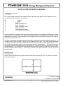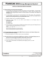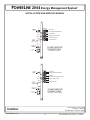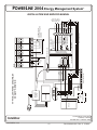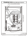
1
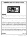
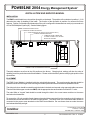
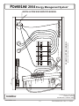
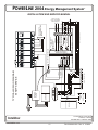
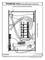
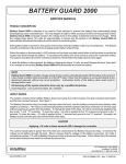
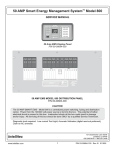
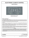
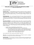
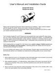
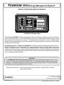
POWERLINE 2004 Energy Management System
TM
INSTALLATION AND SERVICE MANUAL
00-00903-250 Display Panel
The PowerLine 2004 EMS is a specialized power distribution and energy management system intended to be
used in recreational vehicles. The Control Module is housed in the standard main distribution panel, a sheet
metal enclosure with removable front panel. The Display Panel is mounted to a wall or suitable surface
remotely from the distribution panel. It provides a system of energy management to minimize the over-loading
and tripping of circuit breakers.
TM
Energy Management - the PowerLine 2004 EMS automatically senses the available power to the vehicle. It
determines whether it is connected to a 120 VAC, 30 Amp shore power source, 240 VAC, 50 Amp shore power
source, or Generator source. Depending upon available power, it controls the operation of the rear air
conditioner fan and compressor using low voltage switching and also controls the refrigerator by switching the
120 VAC supply. If the available power source is 120 VAC, 30 Amp shore power it attempts to keep the total 120
volt current draw to less than 30 Amps.
TM
CAUTION
The POWERLINE 2004 Energy Management System is a specialized power switching center. Power
from the 120/240 volt power source is fed into the box. The potential of lethal electrical shock is present
in this box. Inadvertent shorts at this box could result in damage and/or injury. All servicing of this box
should be done only by a qualified Service Technician.
TM
Diagnostic tools required: Low current Test Light, Accurate Voltmeter (digital readout preferred)
Clamp-on AC ammeter.
131 Eisenhower Lane North
Lombard, IL 60148
630.268.0010 / 1.800.251.2408
Intellitec
www.Intellitec.com
1
P/N 53-00911-000 Rev. A 112204
POWERLINE 2004 Energy Management System
TM
INSTALLATION AND SERVICE MANUAL
HOW IT WORKS
ENERGY MANAGEMENT
The main neutral line is routed through the magnetically coupled current sensor. This sensor measures the
current flowing through the neutral line, which is the total amount being drawn by all the 120 volt appliances in
the RV. When this current exceeds 30 Amps (20 Amps if the threshold has been set lower), the PowerLine
2004 EMS will turn off the controlled loads in an effort to bring the total current to the limit of the incoming
service.
TM
CONTROLLED LOADS
The system offers control of up to four powered loads. Loads that are to be controlled are connected to one of
the relay circuits of the EMS. There are a total of four control relays in the EMS. Two of these relays (relay 1
rated at 20 Amps & relay 2 rated at 10 Amps), are relays with normally-closed contacts used to interrupt the 120
volt power to the loads. These circuits are intended to control 120 volt appliances such as refrigerator, water
heater, washer/dryer, coffee maker, etc. For the 120 VAC switched loads, power is routed from the individual
branch circuit breakers to one of these 120 VAC relays. The controlled load is then fed from that relay.
The remainder of the relays, relays 3 and 4, are intended to switch low voltage loads. Relay 3 is a single- pole,
double-throw relay with all contacts available. Relay 4 is a single-pole double-throw relay with only the common and
normally-closed contacts available. These are intended to control air conditioners or other appliances equipped
with low voltage controls or thermostats. The contacts of the relays are typically wired in series with the low voltage
controls or thermostats of air conditioners so the EMS turns off only the compressor, or the compressor and fan.
These circuits could also control other 120 volt appliances if an additional control relay is added externally.
If 120 VAC or 240 VAC is not available at the L1 or L2 inputs (J4 pin 4 and 6 respectively) to the Control Module, the
EMS shuts itself off and all relay contacts remain closed. This feature is intended to prevent the EMS from drawing
current from the +12 VDC battery supply when not in operation.
SYSTEM COMMUNICATIONS
The Powerline 2004 EMSTM Control Module utilizes Intellitec’s RV Multiplex/PMC (Programmable Multiplex
Control) System as the communications link between the Display Panel and the Control Module. As an additional
diagnostic feature, the system includes two Communication Status LED’s on the Control Module. In normal
operation, when the Control Module is configured in the Stand-Alone Mode, or as the RV Multiplex system, the
green “IPX OK” LED should be lit and the red “IPX Fail” LED should not be lit.
Utilizing the RV Multiplex/PMC system, the Smart EMS System can:
1) Operate as a Stand-Alone system.
2) Operate as a RV Multiplex System master in a RV Multiplex System allowing other devices such as
inverter/converters, input and output modules, and switch panels, to communicate with each other and the
Smart EMS System.
3) Operate as a PMC Transceiver with the addition of a PMC Central Processing Unit (CPU).
POWERLINE EMS OPERATES IN 4 DIFFERENT MODES:
In operation, when the 120 VAC or 240 VAC power is applied, the system automatically powers up and determines
the nature of the power source.
50 Amp
Genset
30 Amp
20 Amp
131 Eisenhower Lane North
Lombard, IL 60148
630.268.0010 / 1.800.251.2408
Intellitec
www.Intellitec.com
2
P/N 53-00911-000 Rev. A 112204
POWERLINE 2004 Energy Management System
TM
INSTALLATION AND SERVICE MANUAL
OPERATION WHEN CONNECTED TO 240VAC, 50 AMP SERVICE:
If 240 VAC, 50 Amp service is present at the L1, L2 and neutral inputs, the energy management feature is disabled
and the Control Module sends a signal to the Display Module which causes the load meter to go blank, the 50 AMP
service indicator to light, and all power status indicators to light.
OPERATION WHEN THE GENERATOR IS RUNNING:
If the generator is running, 120 VAC will be present at the L1 or L2, and neutral inputs and a +12 VDC signal will be
present at J3 pin 8 on the Control Module. In this mode the energy management feature is disabled and the Control
Module sends a signal to the Display Module which causes the load meter to display actual load current, the GEN
SET service indicator to light, and all power status indicators to light.
OPERATION WHEN CONNECTED TO 120VAC, 30 AMP SERVICE:
If 120 VAC is present at the L1, or L2 and neutral inputs and no +12 VDC signal is present at J3, pin 8 on the Control
Module the EMS will assume that 120 VAC, 30 Amp shore power is available and the energy management feature
will be enabled. The Control Module sends a signal to the Display Module, which causes the load meter to display
actual load current and the 30 Amp service indicator to light. The power status indicators will light when power is
available to run its corresponding load.
Initially, all relay contacts are closed. The total current is monitored. If the total current should exceed the service
limit, the system will turn off the first load in the shedding table. As it does this, it calculates the amount of current that
was removed, which is the value for that load. This value is placed in memory. If the current remains above the
service limit, the system will turn off the next load in the shedding table. Again, it calculates the amount of current that
was removed and places this value, which is the value for that load, in memory. In like manner the system turns off
loads until the total current falls below the service limit or all of the four controlled loads have been shed. In this
process the system has "learned" the amount of current that each particular load draws. This feature compensates
for the differences in current draw over a range of line voltage and ambient temperature, by re-learning the load each
time it is turned off or "shed".
The system now waits until the total current is lower than the service limit and enough current is available, as
compared with the amount in memory for the last load shed, before it will turn that load back on. This assures that
there is sufficient current to operate the load.
There is a two minute minimum delay period after a load is shed before the load will be turned back on again to
prevent air conditioners from turning on with a head of pressure.
OPERATION WHEN CONNECTED TO 120VAC, 20 AMP SERVICE:
If EMS is connected to 30 Amp service, but only 20 Amp service is available, the user must select the 20 AMP service
mode by momentarily pressing the 20/30 Amp select switch on the Control Panel. EMS operates the same in 20
Amp mode as it does in 30 Amp mode, except the total current is limited to 20 Amps.
131 Eisenhower Lane North
Lombard, IL 60148
630.268.0010 / 1.800.251.2408
Intellitec
www.Intellitec.com
3
P/N 53-00911-000 Rev. A 112204
POWERLINE 2004 Energy Management System
TM
INSTALLATION AND SERVICE MANUAL
DISPLAY PANEL
The Display Panel can be mounted remotely and connects to the Control Module with a small gauge, three wire
cable.
Four Power Status LED's indicate whether power is applied to those loads. These LED's are on when the power is
applied.
A two digit display, the Load Meter, indicates the amount of current actually being drawn by all the appliances in the
coach.
The Service Select button allows the current threshold to be changed between 30 Amps or 20 Amps, to match the
incoming service. When 120 VAC power is first applied, the system will always be in the 30 Amp mode. Momentarily
pressing this button will switch the system to the 20 Amp mode.
Four Service Type LED's indicate the type of service that the system is operating under. If the GEN SET service
indicator is lit, the system has automatically detected the presence of 120 VAC at the L1 and L2 inputs and the
presence of the +12 VDC run signal from the generator at the GEN SET input on the Control Module. If the 50 AMP
service indicator is lit, the system has automatically detected the presence of 240 VAC at the L1 and L2 inputs on the
control module. If the 30 AMP service indicator is lit, the system has automatically detected the presence of 120 VAC
at the L1 and L2 inputs and the absence of the +12 VDC run signal from the generator input on the Control Module. If
the 20 AMP service indicator is lit, the user has selected that mode by momentarily pressing the 20/30 Amp select
button. Momentarily pressing this button again will switch the system back to the 30 Amp mode.
This panel can also be used to display the value of current stored in memory for each of the four loads. Pressing and
holding the 30/20 Amp Select button for 3 seconds, will cause the top power status indicator to light. The load meter
will only display the "learned" current (not the present current) for that load.
Subsequent presses of the button will step the display down through each individual power status indicator and
display the "learned" current for that particular load. NOTE: If a load has not been shed, the system will not have had
a chance to learn the current and the default value of zero (0) will display. After a short period of no activity, the
display will automatically return to normal operation.
131 Eisenhower Lane North
Lombard, IL 60148
630.268.0010 / 1.800.251.2408
Intellitec
www.Intellitec.com
4
P/N 53-00911-000 Rev. A 112204
POWERLINE 2004 Energy Management System
TM
INSTALLATION AND SERVICE MANUAL
INSTALLATION
The EMS Control Module has a six position dip-switch on the board. The position of the switches in position 1, 2, &3
determine the order of shedding of the loads. The function of the dip-switch in position 4 is reserved for future
features. Position 5 of the dip-switch determines if the unit is configured in the stand-alone mode (on) or as a slave in
a RV or PMC Multiplex System (off). See the following figure.
COMMUNICATIONS OK IND.
COMMUNICATIONS FAILURE IND.
CONFIGURATION DIP SWITCH (Factory Default=All On)
CURRENT TRANSDUCER INPUT
COMMUNICATION CONNECTOR
TO DISPLAY PANEL and/or RV/PMC
MULTIPLEX SYSTEM
654321
POWER & LOW VOLTAGE RELAY OUTPUTS
These dip-switches are all set to the ON position at the factory. Changing their settings will alter the order of
shedding to suit the particular need of the installation. Please consult the factory before modifying the position of the
dip-switches.
PLACEMENT
The EMS Control Module is installed inside the main distribution panel. The metal mounting bracket should be
placed as shown and the single screw mounting the breaker panel should be removed and replaced as shown.
The wiring to the box should be routed through the holes in the back and secured using approved cable connectors.
The wires should be copper conductors ONLY, with the appropriate size and insulation to meet N.E.C. code.
The main White or "neutral" lead should be routed through the hole in the current sensor and then to the screw
terminal on the Neutral Bar.
To connect the 120 volt controlled loads, jumper wires should be connected from the respective circuit breakers to
the associated screw terminals on the EMS Control Module. The black wires to the controlled loads should be
connected to the proper screw terminals on the EMS Control Module. Be sure these wires are under the screw
terminals and that they are tight.
131 Eisenhower Lane North
Lombard, IL 60148
630.268.0010 / 1.800.251.2408
Intellitec
www.Intellitec.com
5
P/N 53-00911-000 Rev. A 112204
POWERLINE 2004 Energy Management System
TM
INSTALLATION AND SERVICE MANUAL
PLACEMENT continued)
The 12 VDC voltage connections are made through the 8 pin Mate-N-Lok plug on the low voltage side of the
Control Module. The connections are as follows:
Pin
1
2
3
4
5
6
7
8
Function
+ 12 Volts
Ground
Relay 3 Normally Open
Relay 3 Common
Relay 3 Normally Closed
Relay 4 Common
Relay 4 Normally Closed
Gen. Set Run +12 VDC Input
The +12 volts should be supplied from a source fused at 5 Amps minimum and capable of delivering up to 1 Amp of
AVERAGE current. Protecting this connection with a higher rated fuse is acceptable since the EMS is internally
protected with 5 Amp fuse. The low voltage wires are brought into the box through the large hole in the lower lefthand corner of the back of the box.
The Relay 3 connections are typically made to the low voltage compressor control wires of the air conditioners. The
normally closed contacts are wired in "series" with the compressor control lead. This means that the compressor
control wire is cut and the two ends are wired to the Common and the Normally Closed contacts of Relay 3. In this
way, the EMS can interrupt the operation of the compressor, just as the thermostat does. The Relay 4 connections
are typically made to the thermostat wires of the air conditioners. The normally closed contacts are wired in "series"
with the thermostat. This means that the thermostat wire is cut and the two ends are wired to the Common and the
Normally Closed contacts of Relay 4. In this way, the EMS can interrupt the operation of the fan, just as the
thermostat does.
REMOTE PANEL
Select a convenient location for the panel, where it can be easily viewed by the owner. Cut a hole in the panel
for the panel as shown.
131 Eisenhower Lane North
Lombard, IL 60148
630.268.0010 / 1.800.251.2408
Intellitec
www.Intellitec.com
6
P/N 53-00911-000 Rev. A 112204
POWERLINE 2004 Energy Management System
TM
INSTALLATION AND SERVICE MANUAL
REMOTE PANEL (continued)
Route the harness from the hole for the Display Panel to the EMS Control Module (up to 40 feet of cable is
acceptable). Plug the cable into the EMS Control Module, assuring it is properly seated on all four pins. (Note: This
cable is polarized, the latches of each end of the connector mate to each other, and will go on easily in the right
direction.)
The Remote Panel should be plugged onto the harness observing the polarity as before. The panel should then be
installed in the hole and screwed in place using two # 6, flat head screws through the holes in the panel. The white
function label should be lettered to correspond to the order of load shedding and installed. The cover label should be
placed against the front panel in the trim bezel snapped on to hold the label in place.
PERFORMANCE TEST
The system is now ready for testing.
At the installers preference, to assure there are no potential shorts, a Hi-Pot test can be performed on the installation.
The Hi-Pot test should be conducted in accordance with standard procedures for the tester being used.
SYSTEM TEST
Initially, all the 120 volt loads should be turned off or disconnected. Both 120 volt AC and 12 volt DC power should
now be applied to the system. Referring to the Display Panel, the numeric display should read "0" and the four load
LED's should come on. A clamp-on type ammeter may be used to measure the current being supplied by the 30 Amp
shore power cord.
Connect or turn on one of the controlled AC loads. It should operate and the numeric display or the clamp-on
ammeter should show the amount of current that load is drawn. Turn that appliance off and repeat this with each of
the others.
To test the load shedding, turn on all the controlled appliances. The total current drawn should exceed 30 Amps. (If
not - add additional loads to the non-controlled receptacles.) When the total amount of current exceeds 30 Amps,
the loads should begin to turn off to bring the total below 30 Amps.
While connected to 30 Amp service, press the 30/20 Amp Select buttton and watch the system toggle between 30
Amp and 20 Amp service.
Plug the system to 50 Amp service. The 50 Amp service indicator should light.
Start the Generator. The Gen Set service indicator should light.
131 Eisenhower Lane North
Lombard, IL 60148
630.268.0010 / 1.800.251.2408
Intellitec
www.Intellitec.com
7
P/N 53-00911-000 Rev. A 112204
POWERLINE 2004 Energy Management System
TM
INSTALLATION AND SERVICE MANUAL
FUSES
CAUTION
F1 - 5 Amp ATO type, for EMS circuitry only. DO NOT replace with a fuse of higher rating. This could result in
severe damage to the circuitry or create a possible fire hazard.
PLUGS - PINS & FUNCTIONS
J2 - 4 pin AMP (Tyco) Mate-N-Lock
Pin
1
2
3
4
Function
Power
Data-In
Ground
Aux. Master Com-Out
J3 - 8 pin in-line AMP (Tyco) Mate-N-Lock
Pin
1
2
3
4
5
6
7
8
(Mating Housing AMP (Tyco) 1-480702-0)
(Mating housing AMP (Tyco) 640586-1)
Function
+ 12 Volts
Ground
Relay 3 Normally Open
Relay 3 Common
Relay 3 Normally Closed
Relay 4 Common
Relay 4 Normally Closed
+12Vdc Generator Run indicator input
J4 - 6 position terminal block - Will accept up to 12 GA or 14 GA copper wire ONLY.
Terminal
1
2
3
4
5
6
Function
Neutral
From Circuit Breaker for Relay 2
Output of Relay 2
From Circuit Breaker for Relay 1 - Line 1 (L1) Input
Output of Relay 1
Line 2 (L2) Input
J1 - Remote Current Sensor
Pin
1
2
2 pin KK. 156 connector
Current Sensor
Current Sensor
131 Eisenhower Lane North
Lombard, IL 60148
630.268.0010 / 1.800.251.2408
Intellitec
www.Intellitec.com
8
P/N 53-00911-000 Rev. A 112204
POWERLINE 2004 Energy Management System
TM
INSTALLATION AND SERVICE MANUAL
Trouble Shooting
If the following problems occur, proceed with their analysis in the order in which the steps are listed.
I.
No 120 volt appliances working.
A. Check incoming power source.
1. Make sure that the shore power cord is plugged into the outlet.
2. Check the circuit breaker at the shore power outlet to be sure it is set.
Turn it off and then back on to be sure.
3. Check the Main circuit breaker in the distribution panel to be sure it is set.
Turn it off and then back on to be sure.
4. Using a circuit checker, be sure the 30 Amp shore power outlet has 120 volts available.
B. Check Change-Over relay, if so equipped.
1. Measure the voltage at the incoming side of the Main 30 Amp breaker.
If voltage is NO the same as the incoming line, repair the change-over.
(Refer to the change-over service literature for trouble shooting.)
II. 120 volts available at non-controlled appliances and receptacles.
Controlled appliances do not operate.
A. Check Main and all branch 120 volt circuit breakers in the distribution panel.
1. Reset circuit breakers if necessary.
2. Check for presence of voltage at branch circuit breakers with voltmeter.
III. Some controlled appliances turn on, others do not.
A. Check wiring to and from EMS Control Module.
1. Check wiring from circuit breakers to EMS Control Module.
2. Check wiring from EMS Control Module to controlled appliance.
B. Make sure enough power is available to run these loads.
1. Turn off other appliances.
IV. Branch circuit breaker trips when power is applied.
A. Check wiring for shorts.
V. Air conditioner doesn't work.
A. Check thermostat wiring and settings.
B. Check air conditioner
VI. Shedding order incorrect.
A. Check for jumpers in locations 1, 2, and 3 on the EMS Control Module.
B. Check relay wiring.
131 Eisenhower Lane North
Lombard, IL 60148
630.268.0010 / 1.800.251.2408
Intellitec
www.Intellitec.com
9
P/N 53-00911-000 Rev. A 112204
POWERLINE 2004 Energy Management System
TM
INSTALLATION AND SERVICE MANUAL
VII. Remote Display out or strange characters appear.
A. Check the green “IPX OK” and red “IPX Fail” LED indicators on the Control Module. If communication
is present at the Control Module the “IPX OK” indicator will be lit, and the “IPX Fail” indicator will be
extinguished. The wiring should be checked for continuity between J5 on the EMS Control Module and
the Display Panel.
B. If communications is not present at the Control Module the “IPX OK” indicator will be extinguished,
and the “IPX Fail” indicator will be lit. The wiring between J5 on the EMS Control Module and the
Display Panel should be checked for shorts to ground and other circuits.
C. Check the 3 Amp Fuse (F1) on the EMS Control Module.
D. Check the 3 pin cable from the EMS Control Module to the Display Panel for
the following voltages:
Pin 1 (12V)= 12V
Pin 2 (Data)=9V
Pin 3 (GND)= GND
E. Check the harness so that the plug at the EMS Control Module and the plug at the Display Panel are
plugged in with the proper polarity and the pins correspond.
Wiring
1:1 2:2 3:3
Both the EMS and Display have internal protection.
Shorts or miswiring should not cause the units to fail.
VIII. All Load Indicators do not light and the GEN SET service indicator on the Remote Display does
not light with the Generator Running.
A. Check for the presence of +12Vdc at J3 pin 8 on the Control Module.
IX. All Load Indicators do not light and the 50 AMP service indicator on the Remote Display does not
light with the vehicle plugged into 240Vac, 50 Amp shore power service.
A. Check for the presence of 240Vac between J4 pin 4 (L1) and J4 pin 6 (L2).
B. Check 120 volt circuit breaker in the distribution panel supplying J4 pin 4 (L1) on the
Control Module.
131 Eisenhower Lane North
Lombard, IL 60148
630.268.0010 / 1.800.251.2408
Intellitec
www.Intellitec.com
10
P/N 53-00911-000 Rev. A 112204
POWERLINE 2004 Energy Management System
TM
INSTALLATION AND SERVICE MANUAL
J1
CURRENT
SENSOR
CONN.
NEUTRAL BAR
FROM REFRIG/CONVERTER BREAKER
RELAY 2
TO REFRIGERATOR
LINE 1
FROM WATER HEATER BREAKER
RELAY 1
TO WATER HEATER RELAY
REMOTE
DISPLAY
PANEL
CONNECTOR
LINE 2
TO CONVERTER RECPT
LOW VOLTAGE
CIRCUIT
CONNECTOR
50 AMP SERVICE
CONNECTIONS
5A / 12VOLT
FUSE
CURRENT
SENSOR
CONN.
(WITH WATER HEATER)
J1
NEUTRAL BAR
FROM REFRIG/CONVERTER BREAKER
RELAY 2
TO REFRIG
LINE 1
FROM WATER HEATER BREAKER (OPTIONAL)
RELAY 1
TO WATER HEATER (OPTIONAL)
LINE 2
TO CONVERTER RECPT
REMOTE
DISPLAY
PANEL
CONNECTOR
LOW VOLTAGE
CIRCUIT
CONNECTOR
30 AMP SERVICE
CONNECTIONS
3A / 12VOLT
FUSE
(OPTIONAL: WATER HEATER)
131 Eisenhower Lane North
Lombard, IL 60148
630.268.0010 / 1.800.251.2408
Intellitec
www.Intellitec.com
11
P/N 53-00911-000 Rev. A 112204
Intellitec
12
OPTIONAL
LOAD
WATER HEATER
REFRIGERATOR
FRONT (A/C 1)
AIR CONDITIONER
GEN-SET
AUTOMATIC
TRANSFER
SWITCH
INSULATED NEUTRAL
BRKR #1
LINE 1
120 VOLT SIDE
NEUTRAL
BRKR #2
RELAY #2
RELAY #1
8
7
6
5
4
3
LOW VOLTAGE WIRING
12 VOLT SIDE
RELAY #4 N.C.
RELAY #4 COM.
RELAY #3 COM.
2
1
GEN-RUN LIGHT
FRONT A/C1 FAN
FRONT A/C1 FAN
FRONT A/C1 COMP
FRONT A/C1 COMP
GROUND
COACH BAT (+)
120 VOLTS TO
UN-CONTROLLED
LOADS
RELAY #3 N.O.
GROUND
+12 VOLTS
CONNECTOR
REMOTE DISPLAY
CONNECTOR
J1 CURRENT SENSOR
TO CURRENT SENSOR CONN.
OPTIONAL
LINE 2
Off/O Off/O
Off/O Off/O
Off/O Off/O
Off/O Off/O
Off/O Off/O
TO AUTO
TRANSFER SW.
A/C2
On/l On/l
15
20
On/l On/l
20
15
On/l On/l
15
15
On/l On/l
15
20
On/l On/l
20
30
MAIN
BARRIER
www.Intellitec.com
ENERGY MANAGEMENT
CONTROL ELECTRONICS
TYPICAL WIRING DIAGRAM
30 AMP SERVICE
POWERLINE 2004 Energy Management System
TM
INSTALLATION AND SERVICE MANUAL
131 Eisenhower Lane North
Lombard, IL 60148
630.268.0010 / 1.800.251.2408
P/N 53-00911-000 Rev. A 112204
AIR CONDITIONER
THERMOSTAT LEADS
LOAD 1.0A, 24VDC
www.Intellitec.com
Intellitec
13
GROMMET
3A / 12VOLT
FUSE
LINE 2
RELAY 1
LINE 1
RELAY 2
LOW VOLTAGE
CIRCUIT
CONNECTOR
REMOTE
DISPLAYPANEL
CONNECTOR
TO CURRENT J1
SENSOR
ALL
NEUTRALS
TO A/C
CIR#1
Off/O Off/O
On/l On/l
15
15
Off/O Off/O
On/l On/l
15
20
Off/O Off/O
On/l On/l
15
20
(WITH ELECTRIC WATER HEATER)
30 AMP SYSTEM WIRING
TO CONVERTER
TO REFRIGERATOR
Off/O Off/O
On/l On/l
20
15
TO TRANSFER SW CIR#2
Off/O Off/O
On/l On/l
30
20
TO WATER
HEATER
ALL GROUNDS
FROM AUTO
TRANSFER SWITCH
TO GROUND
POWERLINE 2004 Energy Management System
TM
INSTALLATION AND SERVICE MANUAL
131 Eisenhower Lane North
Lombard, IL 60148
630.268.0010 / 1.800.251.2408
P/N 53-00911-000 Rev. A 112204
www.Intellitec.com
Intellitec
14
GROMMET
3A / 12VOLT
FUSE
LINE 2
RELAY 1
LINE 1
RELAY 2
LOW VOLTAGE
CIRCUIT
CONNECTOR
REMOTE
DISPLAYPANEL
CONNECTOR
TO CURRENT J1
SENSOR
ALL
NEUTRALS
TO A/C
CIR#1
Off/O Off/O
On/l On/l
15
15
Off/O Off/O
On/l On/l
15
20
Off/O Off/O
On/l On/l
15
20
(WITHOUT ELECTRIC WATER HEATER)
30 AMP SYSTEM WIRING
TO CONVERTER
TO REFRIGERATOR
Off/O Off/O
On/l On/l
20
15
TO TRANSFER SW CIR#2
Off/O Off/O
On/l On/l
30
20
ALL GROUNDS
FROM AUTO
TRANSFER SWITCH
TO GROUND
POWERLINE 2004 Energy Management System
TM
INSTALLATION AND SERVICE MANUAL
131 Eisenhower Lane North
Lombard, IL 60148
630.268.0010 / 1.800.251.2408
P/N 53-00911-000 Rev. A 112204
Intellitec
15
OPTIONAL
LOAD
WATER HEATER
REFRIGERATOR
FRONT (A/C 1)
AIR CONDITIONER
GEN-SET
AUTOMATIC
TRANSFER
SWITCH
INSULATED NEUTRAL
BRKR #1
LINE 1
120 VOLT SIDE
NEUTRAL
BRKR #2
RELAY #2
RELAY #1
OPTIONAL
LINE 2
RELAY #4 N.C.
RELAY #4 COM.
RELAY #3 COM.
RELAY #3 N.O.
GROUND
+12 VOLTS
8
7
6
5
4
3
2
1
GEN-RUN LIGHT
FRONT A/C1 FAN
FRONT A/C1 FAN
FRONT A/C1 COMP
FRONT A/C1 COMP
GROUND
COACH BAT (+)
120 VOLTS TO
UN-CONTROLLED
LOADS
Off/O
20
On/l
LOW VOLTAGE WIRING
12 VOLT SIDE
TO CURRENT SENSOR CONN.
Off/O Off/O
On/l On/l
15
15
J1 CURRENT SENSOR
CONNECTOR
REMOTE DISPLAY
CONNECTOR
Off/O Off/O
Off/O Off/O
Off/O Off/O
Off/O Off/O
TO A/C 2
REAR AIR
On/l On/l
15
15
On/l On/l
15
15
On/l On/l
20
50
On/l On/l
20
50
MAIN
BARRIER
www.Intellitec.com
ENERGY MANAGEMENT
CONTROL ELECTRONICS
TYPICAL WIRING DIAGRAM
50 AMP SERVICE
POWERLINE 2004 Energy Management System
TM
INSTALLATION AND SERVICE MANUAL
131 Eisenhower Lane North
Lombard, IL 60148
630.268.0010 / 1.800.251.2408
P/N 53-00911-000 Rev. A 112204
AIR CONDITIONER
THERMOSTAT LEADS
LOAD 1.0A, 24VDC
www.Intellitec.com
Intellitec
16
LINE 2
RELAY 1
LINE 1
RELAY 2
GROMMET
3A / 12VOLT
FUSE
LOW VOLTAGE
CIRCUIT
CONNECTOR
REMOTE
DISPLAYPANEL
CONNECTOR
TO CURRENT J1
SENSOR
ALL
NEUTRALS
TO A/C
Off/O Off/O
On/l On/l
15
15
Off/O Off/O
On/l On/l
15
15
TO CONVERTER
TO REFRIGERATOR
Off/O Off/O
On/l On/l
20
50
Off/O Off/O
On/l On/l
15
15
50 AMP SYSTEM WIRING
TO A/C
Off/O Off/O
On/l On/l
20
50
Off/O
20
On/l
ALL GROUNDS
TO WATER
HEATER
FROM AUTO
TRANSFER SWITCH
TO GROUND
POWERLINE 2004 Energy Management System
TM
INSTALLATION AND SERVICE MANUAL
131 Eisenhower Lane North
Lombard, IL 60148
630.268.0010 / 1.800.251.2408
P/N 53-00911-000 Rev. A 112204