1
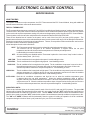
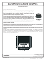
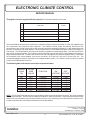
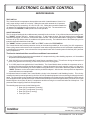
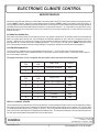
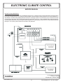
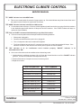
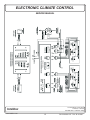
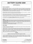
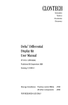
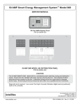
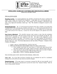
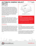
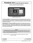
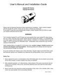
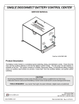
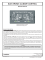
ELECTRONIC CLIMATE CONTROL
SERVICE MANUAL
A/C1
A/C2
00-00591-000 Master Controller
00-00597-000 Display Panel
PRODUCT DESCRIPTION
The ELECTRONIC CLIMATE CONTROL (ECC) System offers automatic and manual control of the A/C1 and A/C2 rooftop air conditioners and furnace/s in the Motor home. The system includes an energy management system that shuts off
the air conditioners, when necessary, to prevent electrical over-load. It also includes a number of features that provide the
owner with the most comfortable temperature controlled environment possible.
In the HEAT mode, the system offers automatic control of the furnace/s in a manner identical to standard wall mount
thermostats.
In either the LOW COOL or HIGH COOL modes, the air conditioner fans run continuously at the selected speed and the
compressors are controlled to maintain the set point temperature. When in the AUTO mode, the unit automatically
controls the compressors and selects the appropriate air conditioner fan speed based on the difference between the set
point temperature and the ambient temperature in the Motor home.
In addition to controlling the temperature within the coach, the system constantly monitors the current being drawn by all of
the 120 VAC electrical appliances, including the air conditioners, and will control the operation of the air conditioners to
prevent them from over-loading the circuit breakers. Once the system turns the air conditioners off, it will keep them off
until there is enough power available to restore normal operation.
CAUTION
The system has been designed to operate from 120 VAC, 30 Amp service only. Connecting the coach to any other
power source will cause the system to operate improperly. If only 20 Amp service is available, “load management”
must be done manually by the owner, and only one air conditioner can be operated at a time, unless the auxiliary
generator is utilized
131 Eisenhower Lane North
Lombard, IL 60148
630.268.0010 / 1.800.251.2408
Intellitec
www.intellitec.com
1
P/N 53-00591-597 Rev. B 041205
ELECTRONIC CLIMATE CONTROL
SERVICE MANUAL
HOW IT WORKS
The System contains two major components, the ECC Thermostat and the ECC Control Module, along with additional
external sensors which are connected to these modules.
THE ECC THERMOSTAT:
The Thermostat allows the owner to set the A/C1 and A/C2 air conditioning and heating systems' modes and temperatures.
The electronics in this panel measure ambient temperatures via two external temperature probes (front and rear). Based
on the mode and set point temperature settings, the probes send appropriate control signals to the ECC Control Module.
These signals are sent via a two wire multiplexed communication link labeled IPX SIG and IPX GND.
There are two identical sets of controls on the panel, one for each of the front (A/C1) and rear (A/C2) systems. The
potentiometers allow the user to select a desired temperature for each system in the range of 50 to 90 degrees Fahrenheit.
Moving the controls down, lowers the set point temperature. The two, seven-position function switches are used to select
the furnace's and air conditioners' operating modes.
A brief description of each mode is as follows:
HEAT - The Thermostat controls the furnace/s to maintain the desired temperature in the coach.
The furnace/s will be energized at an ambient temperature 2 degrees below the set point
temperature and shut off when the ambient temperature is at the set point temperature.
Load shedding is not active in this mode.
OFF - All control settings are disabled and the Thermostat is placed in a low-current “sleep” mode in order to
minimize battery drain. (35-45 mA)
LOW FAN - The air conditioner fan is energized on low speed. Load shedding is active.
HIGH FAN - The air conditioner fan is energized on high speed. Load shedding is active.
LOW COOL - The air conditioner fan is energized on low speed. The air conditioner compressor is turned on when
the ambient temperature goes 2 degrees above the set point temperature and shuts off when the
ambient temperature reaches the set point temperature. Load shedding is active.
HIGH COOL -
The air conditioner fan is energized on high speed. The air conditioner compressor is turned on when the
ambient temperature is 2 degrees above the set point temperature and shuts off when the ambient
temperature reaches the set point temperature. Load shedding is active.
AUTO COOL - Both the air conditioner compressor and high fan are on when the ambient temperature goes
5 degrees above the set point temperature. When the ambient temperature drops to within 2
degrees of the set point, the fan switches to low speed. When the temperature drops to the set point, the
compressor turns off. When the ambient temperature drops 2 degrees below the set point, the fan turns
off. As the ambient temperature rises, the reverse procedure happens. Load shedding is active.
INDICATOR LIGHTS:
There are two indicator lights on the control panel for each of the front (A/C1) and rear (A/C2) systems. The green ON
indicator will be lit when the associated function switch is in any mode, except the "OFF" mode and the system has not
shed the associated air conditioner compressor, or fan. The red "SHED" indicator will be lit when the associated function
switch is in any mode, except the "OFF" mode and the system has shed the associated air conditioner compressor, or fan.
The "ON" and "SHED" indicators will blink alternately when the system is holding off operation of the air conditioner
compressor during the 2 minute "short-cycle" protection cycle. (see ECC Control Module)
131 Eisenhower Lane North
Lombard, IL 60148
630.268.0010 / 1.800.251.2408
Intellitec
www.intellitec.com
2
P/N 53-00591-597 Rev. B 041205
ELECTRONIC CLIMATE CONTROL
SERVICE MANUAL
THE ECC TEMPERATURE PROBES:
These Temperature Probes are thermistors mounted in protective plastic housings so they can
sense the temperature of the air without being influenced by the mounting surface temperature.
Thermistors vary their electrical resistance inversely with temperature; which means, the
higher the temperature, the lower the thermistors' resistance. The thermistors utilized in this
system have a resistance of about 10,000 Ohms at 77 degrees.
There are two temperature probes, one for each of the front (A/C1) and rear (A/C2) systems.
They are located remotely from the thermostat panel to sense temperatures in the front and
rear. The connections to the ECC Thermostat are via small 2 pin connectors labelled J1 (A/C1)
and J4 (A/C2). Since the devices are not polarity sensitive, the two wires leading to them can
be reversed without harm. However, it is necessary to connect the A/C1 and A/C2
TEMPERATURE PROBE to the correct connector to ensure the ECC Thermostat interprets the
correct ambient temperatures associated with the front (A/C1) and rear (A/C2) of the coach.
THE ECC CONTROL MODULE:
The Control Module performs the timing, sequencing, switching, and load shedding functions for the furnace/s, air
conditioner fans and compressors. It is often located under the refrigerator. The circuitry in this module decodes the
control signals sent to it via the multiplexed communication link from the ECC Thermostat.
The Control Module operates the furnace/s by closing a set of relay contacts. The relay contacts for the front furnace are
connected to pins 1 and 2 of connector J4, and the contacts for the rear furnace are connected to pins 4 and 5 of the same
connector.
A/C2
A/C1
The relay contacts are electrically isolated from all other circuitry on the Control Module. The contacts are functionally
equivalent to the contacts on a wall mounted thermostat and are wired to the blue and black thermostat leads from each
furnace. The coach may be equipped with one, or two furnaces. On coaches equipped with one furnace, the furnace
should be wired to pins 1 and 2 of connector J4.
131 Eisenhower Lane North
Lombard, IL 60148
630.268.0010 / 1.800.251.2408
Intellitec
www.intellitec.com
3
P/N 53-00591-597 Rev. B 041205
ELECTRONIC CLIMATE CONTROL
SERVICE MANUAL
The pigtail connector supplied with the system (PC4) utilizes the following color codes:
PC4
/J4
pin
FUNCTION
COLOR
1
FRONT FURNACE THERMOSTAT (BLUE)
WHT/BLUE
2
FRONT FURNACE THERMOSTAT (BLACK)
3
KEYED - NOT CONNECTED
4
REAR FURNACE THERMOSTAT (BLACK)
BLK
5
REAR FURNACE THERMOSTAT (BLUE)
BLU
WHT/BLK
The Control Module operates the air conditioner compressors and fans via three relays with 12 VDC coils supplied by the
A/C manufacturer and mounted in their equipment. The contacts on these relays are internally wired by the A/C
manufacturer to the 120 VAC supply line for each unit and connect the compressor with the low, or high speed taps on the
fan motor to that supply line when operated. The wiring between the Control Module and these relays is low voltage (12
VDC) wiring. The Control Module uses high-side switching to operate the corresponding relays. One side of each of the
relay coils is connected together. This "common" lead is connected to ground through the Control Module and should not
be grounded anywhere else. The other side of each of the coils is brought out to one of three separate leads. These leads
are connected to the Control Module via a four-pin connector: J2 for the A/C1 unit, and J3 for the A/C2 unit. The
corresponding pigtail connectors, PC2 and PC3, are supplied with the system. PC3, the A/C2 (rear) connector, is marked
in red in order to differentiate it from Pc2.
The following table indicates the connection and control states:
MODULE
CONN
PIN
PIGTAIL
WIRE
COLOR
FUNCTION
“ON”
VOLTAGE
“OFF”
VOLTAGE
J2-1
J2-1
J2-3
J2-4
J3-1
J3-2
J3-3
J3-4
BLU
GRY
GRN
YEL
BLU
GRY
GRN
YEL
COMMON
LOW FAN
HIGH FAN
COMPRESSOR
COMMON
LOW FAN
HIGH FAN
COMPRESSOR
<1 VDC
+12 VDC
+12 VDC
+12 VDC
<1 VDC
+12 VDC
+12 VDC
+12 VDC
<1 VDC
<1 VDC
<1 VDC
<1 VDC
<1 VDC
<1 VDC
<1 VDC
<1 VDC
NOTE: The PC2 and PC3 pigtail wire colors are included for reference only to identify the function of the wires emanating
from the Control Module. The wire colors emanating from the A/C1 and A/C2 units may, or may not agree with these colors.
Always refer to the installation manual supplied with the A/C unit, or see “Identifying control lead functions on the A/C unit”,
in order to match the wire color/functions with those on the Control Module.
131 Eisenhower Lane North
Lombard, IL 60148
630.268.0010 / 1.800.251.2408
Intellitec
www.intellitec.com
4
P/N 53-00591-597 Rev. B 041205
ELECTRONIC CLIMATE CONTROL
SERVICE MANUAL
TEST SWITCH:
The Control Module incorporates a three-position test switch located between J2 and J3 to
verify proper wiring to each A/C unit relay. Sliding the test switch towards the J2 operates
A/C1 and high fan by connecting J2-3 and J2-4 to +12V. Sliding the test switch towards the
J3 operates A/C2 and high fan by connecting J2-3 and J2-4 to +12V. The test switch must
be placed in the CENTER, or OFF position for normal operation.
SHORT INDICATOR:
The 12 volt wires feeding the air conditioners are protected from short circuits. If any of these wires are shorted to ground,
the "SHORT" indicator will be lit, indicating the short. To help locate the short, the plugs feeding the air conditioners
should be unplugged, one at a time, to see which cable is at fault. When the shorted cable is unplugged, the "SHORT"
indicator will go out and the other air conditioner will operate normally. The individual wires of the shorted plug can be
tested for shorts to find which one is at fault.
The "SHORT" indicator operates in the "OFF" and "TEST" modes of the TEST SWITCH.
The Control Module also includes protection circuitry to eliminate the possibility of “short-cycling” the A/C compressors.
Short-cycling causes undue stress on the compressor motor when refrigerant pressures are not allowed to stabilized prior
to restarting the compressor. A two-minute timer is incorporated in each of the control systems for the front (A/C1) and rear
(A/C2) compressors.
The timer is started each time one of three conditions is encountered:
1) If the Control Module shuts down the associated A/C compressor during a the shedding sequence, or if the ambient
temperature has reached the set point.
2) If the 120 VAC line current sensed by the Current Sensor goes below 1 Amp. This will occur during an interruption of
power, if the generator is not running, or if the shore power cord is not plugged in.
3) If +12 VDC power is not applied to the Control Module. The Control Module does not allow the compressor to be reenergized until the two-minute period has elapsed. If during this period, the coach requires cooling, or if the unit is
recovering from load-shedding, the Control Module will signal the ECC Thermostat to alternately flash the "ON" and
"SHED" indicators on the control panel until the period has elapsed. After the two minute period has elapsed the
system will return to normal operation.
An important feature included in the Control Module circuitry is the Automatic Load Shedding function. This circuitry
measures the total current being drawn by all of the 120 VAC operated equipment in the coach being fed through the main
panel. The Current Sensor is mounted in the main panel and supplies an input signal to the Control Module. When enough
120 volt appliances are operated so that the current exceeds 30 Amps for more than approximately 3 seconds, the Control
Module begins to shed (shut off) the A/C compressors and fans to bring the current back below the 30 Amp limit. This
prevents nuisance tripping of the main 30 Amp breaker.
The shedding sequence occurs in the following order:
1.
2.
3.
4.
Rear (A/C2) compressor (if running)
Front (A/C1) compressor (if running)
Rear (A/C2) fan (if running)
Front (A/C1) fan
131 Eisenhower Lane North
Lombard, IL 60148
630.268.0010 / 1.800.251.2408
Intellitec
www.intellitec.com
5
P/N 53-00591-597 Rev. B 041205
ELECTRONIC CLIMATE CONTROL
SERVICE MANUAL
When the Control Module sheds any of the loads, it returns a signal to the ECC Thermostat to light the corresponding front,
or rear "SHED" indicator. Based on the shedding sequence, the rear "SHED" indicator will always be the first to light. If
enough appliances are operated to generate a load current of 30 Amps, the Control Module will proceed through the entire
shedding sequence and essentially shut down both A/C compressors and fans. (It is important to note that if the Control
Module has shed all four loads and the line current continues to exceed the 30 Amp limit, it is likely that the 30 Amp line
breaker will open.)
ALTERNATING OPERATION:
If the total current being drawn is such that only one A/C can operate, and the ECC Thermostat continues to demand that
both A/C compressors operate, the Control Module will alternate operation of A/C1 and A/C2 compressors every 30
minutes. When the line current is low enough to allow operation of both air conditioners, the Control Module will restore
their operation in a reverse order to the shedding sequence. The front (A/C1), or rear (A/C2) "SHED" indicators on the
ECC Thermostat will remain lit until the corresponding A/C compressor and fan are restored to normal operation.
SYSTEM INTERCONNECTS:
12 VDC power is supplied to the Control Module via connector J1. This connector also provides the signal
connections between the Control Module and ECC Thermostat, and the Current Sensor. Connector PC1B is part of
the Current Sensor assembly.
The pigtail connector, PC1A, is supplied with the system and is wired per the following table:
J1
PIN
PC1B
PIN
FUNCTION
COLOR
1
1
CURRENT SENSOR
WHT
2
2
CURRENT SENSOR GND
WHT
J1
PIN
PC1B
PIN
FUNCTION
COLOR
3
1
KEYED - NOT CONNECTED
N/C
4
2
+12 VDC POWER
RED
5
3
KEYED - NOT CONNECTED
N/C
6
4
POWER GROUND
BLK
7
5
IPX GND
BRN
8
6
IPX SIG
YEL
THE ECC CURRENT SENSOR:
The Current Sensor is a transformer which converts the AC current passing through its core into a corresponding voltage.
A functional Current Sensor has a resistance of approximately 40 Ohms and produces an AC voltage of 0.1 VAC per Amp
of current passing through the core (10 Amps = 1.0 VAC). The Current Sensor should be mounted in one of the knockouts
in the 120 VAC box so that the donut shaped head is inside the box. The black wire feeding the 30 Amp main breaker in the
120 VAC panel should pass through the hole in the Current Sensor.
131 Eisenhower Lane North
Lombard, IL 60148
630.268.0010 / 1.800.251.2408
Intellitec
www.intellitec.com
6
P/N 53-00591-597 Rev. B 041205
ELECTRONIC CLIMATE CONTROL
SERVICE MANUAL
USE OF THE ECC WITH AUXILIARY GENERATOR SETS
USE WITH 4KW GENERATOR
In systems using 4KW generator sets, the main system includes a manual, or automatic change-over which selects the 30
Amp power feed from either the shore power, or generator. In this situation, all ECC load shedding features will remain
unchanged.
RELAY CONTROLLED
A/C2 REAR
AIR CONDITIONER
P/N 00-00591-200
RELAY CONTROLLED
A/C1 FRNT
AIR CONDITIONER
4.0 KW GENERATOR
131 Eisenhower Lane North
Lombard, IL 60148
630.268.0010 / 1.800.251.2408
Intellitec
www.intellitec.com
7
P/N 53-00591-597 Rev. B 041205
ELECTRONIC CLIMATE CONTROL
SERVICE MANUAL
USE WITH 5 KW GENERATOR
In systems using 5 KW generator sets, an additional change-over, or transfer relay is used to transfer the load of the larger
A/C system (usually the front, A/C1 system) to the generator’s second output to utilize generator's full output capability. In
this situation, the ECC load shedding features will remain unchanged, but the Current Sensor will not measure the load
current going to the larger, A/C1 (front) system when the generator is running. If the measured load currents through the
current sensor continue to exceed 30 Amps with the smaller, A/C2 (rear) system shed, the ECC Control Module will shed
the larger, A/C1 (front) system to prevent over load of the generator.
RELAY CONTROLLED
A/C2 REAR AIR
CONDITIONER
P/N 00-00591-200
RELAY CONTROLLED
A/C1 FRNT AIR
CONDITIONER
0-00568-000
0
131 Eisenhower Lane North
Lombard, IL 60148
630.268.0010 / 1.800.251.2408
Intellitec
www.intellitec.com
8
P/N 53-00591-597 Rev. B 041205
ELECTRONIC CLIMATE CONTROL
SERVICE MANUAL
Trouble Shooting
If the following problems occur, proceed with their analysis using the steps below in the order in which they are
listed:
I. No green "ON" indicator lit, Thermostat in any functional position.
A. Slide the test switch on the Control Module towards J2. A/C1 compressor and high fan should turn on.
If NOT:
1.
2.
3.
Make sure that the power connector (PC1A) is plugged into J1 on the control module.
Make sure that the pigtail keying matches connector keying.
Check the 5A fuse in the distribution panel for Control Module power.
Check for +12VDC at pin 4 of J1 on control module and ground at pin 6.
B. Check the IPX SIG and IPX GND connections to the ECC Thermostat.
If OK:
1.
Measure the DC voltage between the IPX SIG and IPX GND lugs and measure the voltage
between pins 7 and 8 of J1 on the Control Module. The voltage should read greater than 4 VDC and be the
same at both locations. If the voltage is OK at both locations replace the Thermostat.
If NOT:
(a) Check the wiring.
(b) Replace the Control.
II. “ON" indicator is lit, but the position of the set point temperature controls on the ECC Thermostat have no
effect on heat and cool functions on either A/C1 or A/C2 systems. In the HEAT mode, the furnace stays
on all the time. In the COOL modes the fan comes on, but the A/C compressor never comes on.
A. Check the installation of the Temperature probes. The front probe should be connected to J1 and
the rear probe to J4 on the Thermostat. If OK, measure the resistance of the Temp Probe at the connector.
Resistance should be 7,500 to 15,000 Ohms.
If NOT:
1.
2.
Replace Temp Probe.
Replace ECC Thermostat.
III. "ON" indicator is lit, but the A/C compressor never comes on in either the LOW COOL, HIGH COOL, or AUTO
COOL mode, even when the set point control is set to its lowest (cool) position. In the HEAT mode, the
furnace works properly in conjunction with the set point control.
A. Slide the test switch on the Control Module towards J2. Front compressor and high fan should turn on.
If NOT:
1. Check to make sure that the leads on PC2 are connected to their corresponding function at the A/C1 unit.
The wire colors may, or may not match. It is likely that the "common" and "high fan" leads are reversed.
2. Check the continuity of the "Comp Relay" lead between the Control Module and the front A/C unit.
131 Eisenhower Lane North
Lombard, IL 60148
630.268.0010 / 1.800.251.2408
Intellitec
www.intellitec.com
9
P/N 53-00591-597 Rev. B 041205
ELECTRONIC CLIMATE CONTROL
SERVICE MANUAL
B. Slide the test switch on the Control Module towards J3. Rear compressor and high fan should turn on.
If NOT:
1. Check to make sure that the leads on PC3 are connected to their corresponding function at the A/C2 unit.
The wire colors may, or may not match. It is likely that the "common" and "high fan" leads are reversed.
2. Check the continuity of the "Comp Relay" lead between the Control Module and the A/C2 unit.
C. Check to make sure that the connector, PC1B, from the Current Sensor is plugged into J1, pins 1 and 2 and that
the 120 VAC supply lead to the 30 Amp breaker in the distribution panel passes through the hole in the Current
Sensor.
If OK then:
1. Unplug the Current Sensor from the Control Module and measure the resistance across the
leads to the Current Sensor. The resistance should be approximately 40 Ohms.
If NOT:
(A) Replace the Current Sensor.
IV. "ON" indicator is lit, but fans do not operate in LOW FAN, or HIGH FAN modes.
A. Make sure that the coach is plugged in to a "live" shore power outlet.
B. Check the 120 VAC circuit breakers in the distribution panel.
C. Slide test switch on Control Module towards J2. A/C1 compressor and high fan should turn on.
If OK replace Control Module.
If NOT:
1.
Check wiring between PC2 and A/C1 unit.
D. Slide test switch on Control Module towards J3. Rear compressor and high fan should turn on.
If OK, replace Control Module.
If NOT:
1.
Check wiring between PC3 and rear A/C unit.
V. "ON" indicator is lit, but the furnace does not operate in HEAT mode at any thermostat
setting.
A. Check the fuse, or circuit breaker feeding the furnace.
B. Move the set point control up to the highest and down to the lowest temperature settings. Somewhere in between
these settings an audible click should be heard from the relay in the control module.
If NOT:
1.
Replace the Control Module.
C. Disconnect plug PC4 from the Control Module. Placing a shorting jumper between PC4 pins 1 and 2 should
cause the front furnace to energize. Placing a shorting jumper between PC4 pins 4 and 5 should cause the rear
furnace to energize.
If NOT:
1.
Check the wiring between PC4 and the furnace.
131 Eisenhower Lane North
Lombard, IL 60148
630.268.0010 / 1.800.251.2408
Intellitec
www.intellitec.com
10
P/N 53-00591-597 Rev. B 041205
ELECTRONIC CLIMATE CONTROL
SERVICE MANUAL
VI. "SHED" indicator is on in the HEAT mode.
A. This occurs normally within 20 seconds of system power-up. If the shed indicator stays lit and a test of the rest of
the system functions checks OK, replace the Thermostat.
VII. "SHED" indicator is lit when in the FAN, or COOL modes.
A. Current draw is above 30 Amps. Remove 120 VAC appliance loads from the line by turning off all of the breakers
in the distribution panel other than the 30 Amp main and A/C breakers. If the "SHED" indicator still stays on
replace the Control Module.
VIII. "ON" and "SHED" indicators flash alternately in any of the COOL modes.
A. This occurs normally within a two minute period after the following situations:
1. Shore power is plugged in.
2. Generator is started and shore power is not plugged in.
3. The +12 volt power to the control module is first applied.
4. The Control Module has shed an A/C compressor because line current has exceeded 30 Amps. If the
indicators continue to flash after the two-minute period, replace the Control Module.
IX. "ON" indicator is lit, air conditioners won't function properly, "SHORT" indicator is lit
Control Module is "ON".
A. One or more of the wires to the air conditioner/s are shorted to ground.
1. Unplug either air conditioner connector (J2 or J3) from the Control Module to see if the "SHORT" indicator
goes out. The other air conditioner should operate normally.
2. Check individual wires of suspect connector, for short to ground.
3. Repair short in wires.
PART DESCRIPTION
PART NUMBER
Single Furnace Thermostat
00-00597-100
Dual Furnace Thermostat
00-00597-000
Control Module (11k/13.5K BTU AC)
00-00591-200
Current Sensor
01-00233-000
Temp Sensors (2)
00-00569-000
Temp Probe Cables (2) 10 ft.
11-00417-010
Temp Probe Cables (2) 31 ft.
11-00417-031
Temp Probe Cables (2) 50 ft.
11-00417-050
Temp Probe Cables (2) 65 ft.
11-00417-065
Transfer Relay Delay
00-00568-000
Wiring Harness Kit
11-00375-000
131 Eisenhower Lane North
Lombard, IL 60148
630.268.0010 / 1.800.251.2408
Intellitec
www.intellitec.com
11
P/N 53-00591-597 Rev. B 041205
ELECTRONIC CLIMATE CONTROL
P/N 00-00591-200
A/C1
A/C2
SERVICE MANUAL
131 Eisenhower Lane North
Lombard, IL 60148
630.268.0010 / 1.800.251.2408
Intellitec
www.intellitec.com
12
P/N 53-00591-597 Rev. B 041205