1
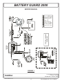
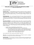
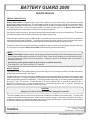
BATTERY GUARD 2000
SERVICE MANUAL
PRODUCT DESCRIPTION
Battery Guard 2000 is intended to be used in Fleet vehicles to prevent the battery from inadvertently being
discharged by some unwanted load. This may happen if a light or other accessory is left on for long periods of time.
Battery Guard 2000 constantly monitors the voltage level on the battery to determine the level of charge. When
the voltage drops below 12.0 volts for approximately 4 minutes and the ignition is off, Battery Guard 2000 will
automatically disconnect the battery from the vehicle’s electrical system.
If the ignition switch is turned on, the system will not disconnect the battery under any circumstances. This feature
prevents a shutdown in the event of a charging system failure while driving.
When the battery is disconnected, a LED indicator on the dash mounted switch blinks to let the driver know that the
system has disconnected the battery. To reconnect the battery, the driver needs to press the momentary switch.
The system now allows the driver 4 minutes to start the vehicle before the battery disconnects again.
If, while the battery is disconnected, the battery voltage goes above 13 volts, as would happen during a “jump start”
or if a charger is connected, Battery Guard 2000 will automatically reconnect the battery.
NOTE
Battery Guard 2000 is a battery charge saving device used to automatically switch off the battery in the event of
a low charge condition while the ignition is in the OFF state. Power from the battery is connected directly to the
disconnect solenoid, without any circuit protection. Inadvertent shorts of the battery cable could result in
damage and/or injury.
All Servicing of the system should be done only by a qualified technician.
Tools Required: Low Current test light, DC voltmeter.
HOW IT WORKS
The system consists of the Intellitec Battery Disconnect relay, the control module, the dash mounted reset switch,
and the inter-connect harness. See Figure 1.
The Battery Disconnect relay is normally mounted under the hood, near the battery to keep the heavy battery cable
length to a minimum. The relay is a mechanically latched unit that maintains electrical connection or remains open
without requiring any power from the battery. To change the state of this relay, 12 volts is momentarily applied to the
two small, “I” and “S” terminals. To open the relay, +12 volts is applied to the “S” terminal and ground to the “I”
terminal. To close the relay, +12 volts is applied to the “I” terminal and ground to the “S” terminal. Normally, the
Battery Guard controller grounds both terminals of the relay.
CAUTION
Applying +12 volts to these terminals WILL damage the controller.
The control module gets its power from the inline fuse connected to the Battery Disconnect relay. It monitors the
voltage on the battery through this lead. When it senses that the voltage on the battery is less than 12.0 volts, it
momentarily applies +12 volts to Battery Disconnect relay to disconnect the power. It then blinks the LED indicator
on the dash mounted reset switch to indicate the disconnect.
131 Eisenhower Lane North
Lombard, IL 60148
630.268.0010 / 1.800.251.2408
Intellitec
www.intellitec.com
1
P/N 53-00660-100 Rev. C 020105
BATTERY GUARD 2000
SERVICE MANUAL
The ignition input signal to the module is used to prevent the module from disconnecting the battery if the ignition
is on. This connection is very important. Failure to make this connection could result in the disconnecting of the
battery while driving.
WARNING
This could lead to serious driving difficulties and a fatal accident.
TESTING
The first step in testing Battery Guard 2000 is to locate and press the RESET switch for a minimum of 3
seconds continuously. This will quickly determine if the system is working properly.
RESET SWITCH TEST
To test the system, turn off the ignition and press the RESET switch for a minimum of 3 seconds continuously.
The battery should be disconnected and the dash mounted indicator should be blinking, momentarily. Press
the RESET switch to reconnect the battery.
Turn the ignition switch on, but DO NOT start the engine. LED should illuminate for 2 seconds. Again, press the
RESET switch and hold for 3 seconds continuously. The disconnect relay should not click, but will remain ON. The
dash indicator should not be blinking.
If these steps work, the system is working properly. If they don’t, check the inline 5 Amp fuse and repeat the first
step. If this fails to make the system work, further testing is required to determine the source of the failure.
SYSTEM TEST
The next step is to determine if the module is driving the Battery Disconnect relay coil. First, the Ignition should
be in the "OFF" position. Connect a test light across the “I” and “S” terminals of the relay. Press the RESET
switch, hold for 3 seconds continuously and observe the light. It should blink on. Press the RESET switch. The
light should blink on again. Failure to do this indicates the module, harness, or RESET switch is defective. The
most probable cause of failure is the module. If the test light blinks but the relay fails to click, the relay is
defective.
BATTERY DISCONNECT RELAY TEST
Before attempting to test the Battery Disconnect relay, UNPLUG the wire harness from the control module.
CAUTION:
Failure to unplug harness before applying +12 volts to these terminals WILL damage the controller.
To latch or turn the relay on, ground the “S” terminal and momentarily apply +12 volts to the “I” terminal. The relay
should click and engage, closing the circuit between the battery and the electrical system. To unlatch or turn off the
relay, ground the “I” terminal and momentarily apply +12 volts to the “S” terminal. The relay should click, opening
the circuit between the battery and the electrical system.
CAUTION: Momentarily apply +12 Volts ONLY, in both cases.
RESET SWITCH
The RESET switch contains a LED and a momentary switch. To test if the switch is faulty, unplug the harness from
the switch. Using a small jumper wire, momentarily short between the black and violet leads of the harness. The
Disconnect relay should click and be on. If the system works using the jumper the RESET switch is defective.
131 Eisenhower Lane North
Lombard, IL 60148
630.268.0010 / 1.800.251.2408
Intellitec
www.intellitec.com
2
P/N 53-00660-100 Rev. C 020105
BATTERY GUARD 2000
SERVICE MANUAL
Trouble Shooting
A. System will not shut down with low
battery.
1. Check orange wire for ignition "hot" only.
2. Check in-line fuse.
3. Check ground connection.
4. Check battery voltage. Battery Guard will not turn off unless
battery voltage is below 12.0 volts and above 10.0 volts for
more than four minutes.
5. Check for blinking "LED" on switch.
a. If "LED" is blinking press the switch and listen for relay to
click.
(1) If relay does not click, replace module.
(2) If relay clicks, press the test switch and hold for
3 seconds. Listen for relay to click again.
(a) If relay does not click, replace module.
(b) If relay clicks but power remains on in the
van, replace relay.
b. If switch is not blinking, replace module.
B. System turns off prematurely.
1. Check battery voltage. If battery voltage is below 12.0 volts
Battery Guard 2000 will turn off.
2. Check fuse connection for corrosion and possible voltage
drop.
3. Check ground connection.
4. Check switch for blinking "LED".
a. If switch is blinking, replace module.
b. If switch does not blink, but power to van is turned off,
replace relay.
C. System will not turn back on after
disconnecting.
1. Check in-line fuse.
2. Check ground connection.
3. Battery voltage must be above 10.0 volts for Battery Guard
2000 to operate.
4. To start test, press switch and hold continuously for 3
seconds.
5. Check for blinking "LED" on reset switch.
a. If LED is not blinking, replace module.
b. If "LED" is blinking, press the reset switch and listen for
relay to click.
(1) If relay does not click, and "LED" continues to blink,
replace reset switch.
(2) If relay does not click, and "LED" stops blinking,
replace module.
(3) If relay clicks but power does not turn on in vehicle,
replace relay.
Note: These trouble shooting techniques are only intended as general guidelines and should not be interpreted as
addressing all possible electrical problems.
131 Eisenhower Lane North
Lombard, IL 60148
630.268.0010 / 1.800.251.2408
Intellitec
www.intellitec.com
3
P/N 53-00660-100 Rev. C 020105
Intellitec
www.intellitec.com
4
RESET
SWITCH
JUMPER
RESET
SWITCH
A
H
A
H
P/N 37-10104-000
& CONNECTIONS
OPTIONAL:
EATON SWITCH
D
E
CONTROL
MODULE
D
E
CONTROL
MODULE
TYPICAL WIRING
DIAGRAM
A - “I” Terminal - White
B - +12 Volts - Red
C - Ground Black
D - “S” Terminal - Brown
E - Ignition Orange
F - Ground Black
G - Switch Violet
H - LED Yellow
Module Connections
DISCONNECT
RELAY
BATTERY GUARD 2000
SERVICE MANUAL
FIGURE 1
131 Eisenhower Lane North
Lombard, IL 60148
630.268.0010 / 1.800.251.2408
P/N 53-00660-100 Rev. C 020105