1
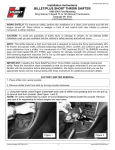
ELECTRIC TRUNK RELEASE
INSTALLATION INSTRUCTIONS
APPLICATION: 1965 - 1970 Mustang
Thank you for purchasing our electric trunk release. Scott Drake has
combined the classic look of the remote cable style trunk release with a
modern electric solenoid function. Our development team has designed
this trunk release to be simple to install. Very little, if any, modification to
the car is needed. Only basic tools are required. Please read all installation instructions before starting.
TOOLS REQUIRED:
• Phillips Screwdriver
• 5/16, 3/8 sockets
• Drill
PREPARATION:
Installation should take approximately 30 minutes or less. Our
electric trunk release includes a chrome release lever/switch assembly,
a custom electric trunk latch, relay and basic wire harness. To preview
the installation, the original mechanical trunk latch will be removed
and replaced with the electric trunk latch. The lever release assembly
is positioned near the driver’s seat and the wiring is routed to a power
source under the dash and to the trunk area.
INSTALLATION INSTRUCTIONS:
Step 1-A: Remove Original Latch Assembly
Open the trunk lid and remove the original latch assembly.
NOTE: In 1965-1966 Mustangs, the lock cylinder and stem remain
in place. In 1967-1970 Mustangs, the lock cylinder must be removed
in order to remove the latch. Make sure the lock cylinder stem is
positioned in the electric latch when installed. DO NOT CLOSE THE
LID UNTIL THE LOCK STEM IS IN THE LATCH OR BEFORE THE
WIRES ARE CONNECTED!
Figure 1A: Mounting the new electric trunk latch
on a 1965-66 Mustang.
Step 1-B: Mounting the new Electric Latch
Check the new electric latch to make sure it is in the “open“ position.
Mount the electric trunk latch assembly in the same location and
secure with the original bolts. (Figures 1A & B)
NOTE: The 1967-1970 Mustangs, only two of the original bolts will
be used. Check how the latch catches and adjust as required.
Step 2: Route the Wires
Route the wire from the latch along the inside of the trunk lid
towards the driver’s side of the car. The Wire should terminate
below the rear deck area behind the back seat or in the wheel well
Figure 1B: Mounting the new electric trunk latch on
a 1967-68 Mustang.
IS.43200-EL
3#/44$2!+%%.4%202)3%3).#s#!33)!7!9s(%.$%23/..6s
ELECTRIC TRUNK RELEASE INSTALLATION INSTRUCTIONS (Cont.)
area behind the back seat or in the wheel a well area. In 1967-1970
Mustangs, the wire will route along the inside edge of the tail panel
and quarter panel following the tail light harness.
Step 3: Removing Parts of the Interior
Remove the driver’s sill plate and kick panel. The remove the bottom
and the back of the rear seat. You may also remove the driver’s side
interior quarter panel but it is not required.
NOTE: We designed the chrome lever release to be positioned next
to the driver’s seat. You may choose a different location but additional
wire may be required. Consider a location that is easy to reach but
will not be accidentally bumped when entering or exiting the vehicle.
Do not mount the release lever under the dash. The release is designed to work properly with the base down.
Step 4: Secure the Lever
After determining the location of the release lever, secure it with the
screws provided. (Figure 2A)
Step 5: Route The Wires
Route the wires under the carpet along the inside edge of the floor.
Route the wire with the relay to the trunk area to meet with the wire
from the trunk latch.
NOTE: You may choose to route the wire under the carpet and back
seat area or along the sill channel and behind the interior quarter
panel. Be careful to located the wire so it will not be pinched between
the panels or hit by an interior screw.
Figure 2A: Securing the trunk release lever.
Step 6: Find a Location and Secure Relay
Thre relay has a ground wire that must be screwed to the body
metal. Choose a location out of view and where the wires will not be
snagged. Secure the relay with adhesive tape.
Step 7: Connect the Relay Wire
Connect the relay wire to the trunk latch wire. Route the power wire
with the fuse clip connector to the fuse panel.
Step 8: Check the Fuses
You can choose to make the trunk release function with the ignition
off or only with the ignition on by which fuse you plug it into. Check
which fuses are “hot“ using a circuit tester with the ignition off.
Repeat the test with the ignition on.
NOTE: You can connect directly to the back of the ignition using your
own wire connector. Consider the advantages and disadvantages of
having the ability to open the trunk without a key in the ignition.
Step 9: Checking the Installation
With the trunk lid closed, pull up on the release lever. (Figure 3A)
Only a light “One Finger“ pull is required. if you wired the release
to function only with the ignition on, make sure the ignition is on.
The trunk lid should pop up about three inches. If the release is not
functioning, check all electrical connections, the ground and power
Figure 3A: Note the clearance on the trunk latch when
checking the installation.
ELECTRIC TRUNK RELEASE INSTALLATION INSTRUCTIONS (Cont.)
source. Check to see how the latch opens with the trunk key. Adjust as
required. Finish the project by replacing the kick panel, sill plate and rear
seats.
TRUNK LID FUNCTION:
Start with the car on a leveled surface. If your trunk lid pops up to the full
open position, you may wish to adjust your trunk lid torsion bars. Follow the
instructions in the Ford service manual under group 17. (Figure 4A)
We do not recommend that the rods be repositioned without the correct tool.
These rods are under a great deal of tension. Injury may result if handled
improperly. Consult an expert if you are not familiar with this process. In
some cases, the torsion bars are positioned at the lightest setting. If the
trunk lid is flying open and there is no further adjustment available. You may
consider adding weight to the lid. Cars with luggage racks or rear spoilers on
the trunk lids may not “pop“ open. Adjusting the torsion bars may help.
CAUTION
Figure 4A: Do not reposition trunk rods without correct
tools.
To place an order, or for current pricing,
call your authorized Scott Drake dealer.
SATISFACTION GUARANTEE:
If you are not happy with this product for any reason or found product to
be defective in manufacturing, simply return it to Scott Drake Enterprises, Inc. within 30 days of purchase and we will replace it - no questions
asked. We stand behind our products one hundred percent, so you can
sit behind the wheel with pride.
* Please call Scott Drake Customer Service for a Return Authorization (RA) before returning any product. Proof of purchase and dated receipt must be present with any return. All
returned products are tested and if found to be damaged by the installer, no replacement
will be issued. You pay the cost to ship to us, we pay for the return shipping. Guarantee
does not include any labor and/or tax charges incurred.
For a list of dealers in your area, or for
any other questions about Scott Drake
products, visit www.scottdrake.com or
call our customer service department
toll free:
1.800.999.0289
Mon - Thurs 7:00 a.m. to 5:00 p.m.
Friday 7:00 a.m. to 4:30 p.m. - PST
130 Cassia Way
Henderson, NV 89014
t: 702.853.2060
f: 702.853.2062