1
Series 50 Fetal Monitors
Series 50 A Antepartum Fetal Monitor (M1351A)
Series 50 IP-2 Intrapartum Fetal Monitor (M1353A)
Series 50 IX/XM/XMO Intrapartum Fetal/Maternal Monitor
(M1350 A/B/C)
Digital Interface Protocol Specifications
Programmer’s Guide
Part Number M1350-9074S
Published in Germany March 2002
Notice
Philips makes no warranty of any kind with regard to this material, including, but not
limited to, the implied warranties of merchantability and fitness for a particular purpose.
Philips shall not be liable for errors contained herein or for incidental or consequential
damages in connection with the furnishing, performance or use of this material.
This document contains proprietary information that is protected by copyright. All rights
are reserved. No part of this document may be photocopied, reproduced or translated to
another language without prior written consent of Philips.
The information contained in this document is subject to change without notice.
Philips assumes no responsibility for the use or reliability of its software on equipment that
is not furnished by Philips.
WARNING! Failure on the part of the responsible individual hospital or institution employing the
use of this equipment to implement a satisfactory maintenance schedule may cause
undue equipment failure and possible health hazards.
Contents
1. Hardware Configuration
About This Guide. . . . . . . . . . . . . . . . . . . . . . . . . . . . . . . . . . . . . . . . . . . . . . . . . . . . . . . . . . . . . . . . . . . . . . . . . .
Introduction . . . . . . . . . . . . . . . . . . . . . . . . . . . . . . . . . . . . . . . . . . . . . . . . . . . . . . . . . . . . . . . . . . . . . . . . . . . . . .
Hardware Configuration . . . . . . . . . . . . . . . . . . . . . . . . . . . . . . . . . . . . . . . . . . . . . . . . . . . . . . . . . . . . . . . . . . . .
Interface Connections . . . . . . . . . . . . . . . . . . . . . . . . . . . . . . . . . . . . . . . . . . . . . . . . . . . . . . . . . . . . . . . . . . . . . .
RS232 Interface . . . . . . . . . . . . . . . . . . . . . . . . . . . . . . . . . . . . . . . . . . . . . . . . . . . . . . . . . . . . . . . . . . . . . . .
RS422 Interface . . . . . . . . . . . . . . . . . . . . . . . . . . . . . . . . . . . . . . . . . . . . . . . . . . . . . . . . . . . . . . . . . . . . . . .
Communication Summary . . . . . . . . . . . . . . . . . . . . . . . . . . . . . . . . . . . . . . . . . . . . . . . . . . . . . . . . . . . . . . . . . . .
1
1
2
3
3
5
6
2. Fetal Monitor Connection
Introduction . . . . . . . . . . . . . . . . . . . . . . . . . . . . . . . . . . . . . . . . . . . . . . . . . . . . . . . . . . . . . . . . . . . . . . . . . . . . . .
The Data Link Layer . . . . . . . . . . . . . . . . . . . . . . . . . . . . . . . . . . . . . . . . . . . . . . . . . . . . . . . . . . . . . . . . . . . . . . .
Special Function Characters . . . . . . . . . . . . . . . . . . . . . . . . . . . . . . . . . . . . . . . . . . . . . . . . . . . . . . . . . . . . . .
The Application Layer . . . . . . . . . . . . . . . . . . . . . . . . . . . . . . . . . . . . . . . . . . . . . . . . . . . . . . . . . . . . . . . . . . . . . .
7
7
8
8
3. Data Block Overview
Introduction . . . . . . . . . . . . . . . . . . . . . . . . . . . . . . . . . . . . . . . . . . . . . . . . . . . . . . . . . . . . . . . . . . . . . . . . . . . . . . 9
Data Block Overview. . . . . . . . . . . . . . . . . . . . . . . . . . . . . . . . . . . . . . . . . . . . . . . . . . . . . . . . . . . . . . . . . . . . . . . 9
Data Blocks . . . . . . . . . . . . . . . . . . . . . . . . . . . . . . . . . . . . . . . . . . . . . . . . . . . . . . . . . . . . . . . . . . . . . . . . . . . . . 10
Request Data Block ‘?’ . . . . . . . . . . . . . . . . . . . . . . . . . . . . . . . . . . . . . . . . . . . . . . . . . . . . . . . . . . . . . . . . . 10
CTG Data Block ‘C’ . . . . . . . . . . . . . . . . . . . . . . . . . . . . . . . . . . . . . . . . . . . . . . . . . . . . . . . . . . . . . . . . . . . 10
Protocol Revision Change Request ‘V’ . . . . . . . . . . . . . . . . . . . . . . . . . . . . . . . . . . . . . . . . . . . . . . . . . . . . 17
Go In Auto Send Mode ‘G’ . . . . . . . . . . . . . . . . . . . . . . . . . . . . . . . . . . . . . . . . . . . . . . . . . . . . . . . . . . . . . 18
Halt Automatic CTG Transmission ‘H’ . . . . . . . . . . . . . . . . . . . . . . . . . . . . . . . . . . . . . . . . . . . . . . . . . . . . 18
Event Message ‘MM’ . . . . . . . . . . . . . . . . . . . . . . . . . . . . . . . . . . . . . . . . . . . . . . . . . . . . . . . . . . . . . . . . . . 19
Note ‘N’ . . . . . . . . . . . . . . . . . . . . . . . . . . . . . . . . . . . . . . . . . . . . . . . . . . . . . . . . . . . . . . . . . . . . . . . . . . . . 19
Failures ‘F’ . . . . . . . . . . . . . . . . . . . . . . . . . . . . . . . . . . . . . . . . . . . . . . . . . . . . . . . . . . . . . . . . . . . . . . . . . . 20
ID-Code ‘I’ . . . . . . . . . . . . . . . . . . . . . . . . . . . . . . . . . . . . . . . . . . . . . . . . . . . . . . . . . . . . . . . . . . . . . . . . . . 21
Maternal (NIBP) ‘P’ . . . . . . . . . . . . . . . . . . . . . . . . . . . . . . . . . . . . . . . . . . . . . . . . . . . . . . . . . . . . . . . . . . . 21
Maternal Temperature ‘T’ . . . . . . . . . . . . . . . . . . . . . . . . . . . . . . . . . . . . . . . . . . . . . . . . . . . . . . . . . . . . . . 22
Maternal Oxygen Saturation ‘S’ . . . . . . . . . . . . . . . . . . . . . . . . . . . . . . . . . . . . . . . . . . . . . . . . . . . . . . . . . . 22
Troubleshooting . . . . . . . . . . . . . . . . . . . . . . . . . . . . . . . . . . . . . . . . . . . . . . . . . . . . . . . . . . . . . . . . . . . . . . . . . . 23
Time Synchronization. . . . . . . . . . . . . . . . . . . . . . . . . . . . . . . . . . . . . . . . . . . . . . . . . . . . . . . . . . . . . . . . . . 23
4. The CRC Mechanism
Introduction . . . . . . . . . . . . . . . . . . . . . . . . . . . . . . . . . . . . . . . . . . . . . . . . . . . . . . . . . . . . . . . . . . . . . . . . . . . . . 25
Using a checksum to detect errors . . . . . . . . . . . . . . . . . . . . . . . . . . . . . . . . . . . . . . . . . . . . . . . . . . . . . . . . . . . . 25
5. Programming Example
Digital data exchange example . . . . . . . . . . . . . . . . . . . . . . . . . . . . . . . . . . . . . . . . . . . . . . . . . . . . . . . . . . . . . . 29
A. Glossary . . . . . . . . . . . . . . . . . . . . . . . . . . . . . . . . . . . . . . . . . . . . . . . . . . . . . . . . . . . . . . . . . . 1
Contents-i
Contents-ii
1
Hardware Configuration
About This Guide
This Programmer’s Guide describes data exchange between a Series 50 fetal monitor and an
obstetrical information management system, such as OB TraceVue, or a PC. It is written
“by a programmer for programmers” - in other words, in technical language.
The User’s Guide and the Installation and Service Guide for OB TraceVue and the fetal
monitors provide general information on fetal monitoring. For a brief explanation of some
of the medical terms used in this Guide, see the Glossary on page A - 1.
This chapter explains what hardware you need for digital information transmission between
the fetal monitor and the host system.
Introduction
Using the digital interface allows you to access the following digital information from the
fetal monitor:
n
Fetal Heart Rate (FHR 1 and FHR 2 if monitoring twins)
n
Maternal Heart Rate
n
Fetal Movement Profile
n
Fetal SpO2 using M1350C (or M1351A/53A and M1350A/B if a Nellcor OxiFirst
Fetal Oxygen Saturation Monitor (N-400) is connected)
n
Toco/IUP Value
n
Noninvasive Blood Pressure
n
Heart Rate Modes
n
Toco/IUP Modes
n
Maternal Blood Pressure
n
Maternal SpO2
n
Maternal Temperature
n
Event Marks
n
Nursing Notes from the Barcode Reader.
It also allows you to send nursing notes from the host system (for example OB TraceVue)
to the fetal monitor.
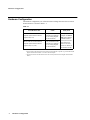
Hardware Configuration
1
Hardware Configuration
Hardware Configuration
The hardware configuration you will need for data exchange between a Series 50 fetal
monitor and a PC is shown in Table 1-1:
Table 1-1
Fetal Monitor Side
Cable
PC/System
M1350A/B/C Fetal Monitor1
Optional System Interface Board
(Option #J10, #12)
Use prefabricated cable
M1380-61612 (RS232)
(or see wiring diagram
in this document)
M1351A/M1353A Fetal Monitor2
Optional System Interface Board
(Option #J10, #13, #14)
Use prefabricated cable
M1380-61613 (RS232)
(or see wiring diagram
in this document)
Host System, for
example OB TraceVue, with an RS232
or RS422 interface
board (see the Installation and Service
Guide for the fetal
monitor for details on
the interface boards)
1. M1350 A/B/C Fetal Monitor must have firmware M1350-6801G or upwards (e.g. M1350-6801H) for
digital communication and Rev C or later to measure FSpO2.
2. All M1351A/M1353A Fetal Monitors have the necessary firmware for the digital communication
built in.
2
Hardware Configuration
Interface Connections
Interface Connections
You can connect a Series 50 fetal monitor to a PC or to an obstetrical information
management system such as OB TraceVue directly using an RS232 cable. Older models
may communicate indirectly via the RS422 interface on the fetal monitor. Both connections
are described in the following.
RS232 Interface
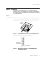
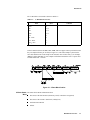
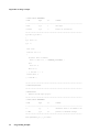
M1351A/M1353A The M1351A and M1353A fetal monitors can be connected directly to the OB TraceVue
or other host system or PC using an RS232 connector cable. The link requires a 24 pin to 9
pin adapter cable (you can use the preconfigured adapter cable, M1380-61613). This cable
connects to the fetal monitor with a 24 pin connector (do not use the 9 pin connector!).
Figure 1-1
M1351A/M1353A showing connecting cable to OB TraceVue
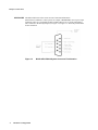
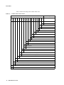
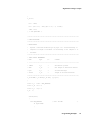
The pin allocation for the RS232 connecting cable is shown below:
Pin 8 RXD Input
Pin 9 TXD Output
Figure 1-2
1
13
2
14
3
15
4
16
5
17
6
18
7
19
8
20
9
21
10
22
11
23
12
24
Pin 24 Signal Ground
RS232 Cable Pin Allocation for the M1351A/M1353A to
Host System Connection
Hardware Configuration
3
Interface Connections
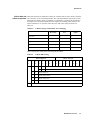
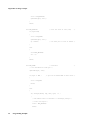
M1350 A/B/C The RS232 link between the Series 50 A/B/C fetal/maternal monitors
(M1350 A/B/C) and the PC or host system, for example OB TraceVue, uses a 9 pin to 9 pin
connection. There is a preconfigured cable available (M1380-61612). On the fetal monitor
side it connects to the Tele/Sys IF port (see Figure 1-5). Figure 1-3 shows the pin allocation
for the connection.
Figure 1-3
4
Hardware Configuration
M1350 A/B/C RS232 System Connector Pin Allocation
Interface Connections
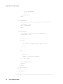
RS422 Interface
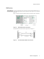
M1351A/M1353A The Series 50 fetal monitors can be connected to a host system using the RS422 interface. If
and M1350 A/B/C you are connecting the M1350A or M1351A/M1353A to a host system or PC you will need
option #J12.
Figure 1-4 shows the location of the RS422 connection on the M1350 A/B/C fetal monitor.
Figure 1-4
M1350 A/B/C Interface Connections
The pin allocation for the RS422 interface signals is shown in Figure 1-5.
Computer
Fetal Monitor
1
2
14
3
15
4
16
5
17
6
18
7
8
9
10
11
12
19
20
21
22
RS422
IN+ pin 18
IN- pin 3
Pin 3 OUT+
Pin 15 OUT-
OUT+ pin 10
OUT- pin 9
Pin 7
Pin17 IN+
Pin 18 IN-
NOT CONNECTED
Pin 12 GND
Shield
1
13
2
14
3
15
4
16
5
17
6
18
7
19
8
20
9
21
10
22
24
11
23
25
12
24
23
13
Figure 1-5
PC to M1350 A/B/C RS422 Cable Connection
Hardware Configuration
5
Communication Summary
Communication Summary
The following is a summary of the protocol settings and parameters:
n
The communication is based on a serial connection, for example RS232 or RS422,
without handshake signals (uses only TxD/RxD).
n
The baudrate is 1200 Baud.
n
Data is sent using 1 start bit, 8 data bits, and 1 stop bit. No parity is used.
n
Data is sent within blocks. These blocks have a CRC-16 code appended to detect
transmission errors.
n
If a data block cannot be received correctly (as detected by the CRC-16 code), it will
not be retransmitted and must be ignored by the receiver.
n
When a word value is transmitted, the most significant byte (MSB) is always sent first.
n
Unknown data blocks are ignored, thus introducing new data blocks in the future does
not disturb the receiver.
n
The maximum response time of the fetal monitor to a request depends on:
n
For ID-Code, CTG-Package:
Transfer time of request
+ 250 msec (max.)
+ rest time of an already started block
+ transfer time of the data-package
n
For other packages:
Transfer time of request
+ 500 msec (max.)
+ rest time of an already started block
+ transfer time of the data-package
Note Some functionality may not be implemented in a specific device (monitor or system). This is
independent of the protocol revision.
6
Hardware Configuration
2
Fetal Monitor Connection
Introduction
The Fetal Monitor connection is defined on three Data Protocol layers:
n
The Physical Layer.
n
The Data Link Layer.
n
The Application Layer.
This chapter describes the data link and application layers of the connection between the
fetal monitor and the host system. The physical layer is described in Chapter 1.
The Data Link Layer
The data link layer is responsible for the correct transmission of data blocks. It ensures the
data that is accepted at the receiver is correct. However it does not tell the transmitter that
the data is received correctly.
In order to achieve 8 bit data transparent transmission, it is necessary to define a data linkage
escape character (DLE). This DLE character announces that the following byte is a special
block control character. If <DLE> occurs in the data stream, it will be replaced by a
<DLE><DLE> sequence to change the control character meaning to a normal character
value. Nevertheless, avoid having the <DLE> character sequence as a typical value in
frequently used data, because that increases the load on the connection.
A data block that is to be sent to the communication partner is surrounded by a block-start
and a block-end. The start block is defined as <DLE><STX> and the end block is
<DLE><ETX>. Following the block, a 2 byte CCITT CRC-16 code is sent to verify the
total block. For a description of the CRC mechanism see Chapter 4.
It is explicitly allowed that data is sent after <DLE><ETX> and before <DLE><STX> and
that data is discarded by the protocol.
The following rules apply to the data blocks:
n
If the CRC cannot be received correctly, the data block is discarded.
n
If a start of block is recognized before an end of block was received, the incomplete
block is discarded and the new block accepted.
Fetal Monitor Connection
7
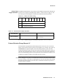
The Application Layer
<DLE>
<STX>
... Block data ...
Start of Block
<DLE>
Data
Table 2-1
<ETX>
<CRC>
End of Block
<CRC>
CCITT CRC
Data Block Structure in the data link layer
The second item also means that the transmitter can stop the transmission of a block at
anytime, and start a new block; for example, to send a very urgent failure message.
Problems can occur if a transmitted message is interrupted directly after the <DLE><ETX>
sequence, (that is, within the CRC bytes). These bytes are read without interpreting <DLE>
codes. The sender should, therefore, send two arbitrary bytes that do not contain one of the
special characters described in Table 2-2, for example, two zero-bytes. After these two bytes
a new block can be started and will be safely recognized.
It is assumed that data transmission errors are very rare, therefore, blocks that are incorrectly
received are not repeated.
Special Function Characters
The special function characters of the Series 50 Digital System Protocol are coded as listed
in Table 2-2. You should avoid using these character sequences in other functions.
Table 2-2
Special Function Characters
Character
Hex Code
Description
<DLE>
10h
Data linkage escape
<STX>
02h
Start of text
<ETX>
03h
End of text
The Application Layer
The application layer describes the data formats as they should be interpreted by the
applications that communicate with each other. The data is embedded in the structure
described in The Data Link Layer on page 2-7. Generally, a data block has the structure
shown in the following table:
Table 2-3
8
Fetal Monitor Connection
General Data Block Structure
Data Block Type
Data...
char
0... 511 Byte
3
Data Block Overview
Introduction
This chapter provides an overview of the individual data blocks. It also gives you a detailed
description of each block and tells you how to initiate transmission.
Data Block Overview
Table 3-1 indicates whether a data block can be transmitted from the host system to the fetal
monitor or from the fetal monitor to the host system. (Note: in this table FM=fetal monitor.)
Table 3-1
Data Block Overview (alphabetically sorted)
Type
Function
Used in direction
FM->Host
Host->FM
Available with
revision
A.01.01
A.02.00
Comments
C
CTG Data Block
*
*
*
F
Failures
*
*
*
G
Go (enter auto)
*
*
*
Start auto-send CTG
data
H
Halt
*
*
*
Stop auto-send mode
I
ID-code
*
*
*
Also sent by FM on
power on
M
Message block
*
*
*
Event messages, eg.
alarm ack. marker
N
Note
*
*
*
Async., both
directions
P
NIBP (Blood Pressure)
*
*
*
Maternal external BP
S
SpO2 (oxygen sat.)
*
*
*
Maternal oxygen
saturation
T
Temperature
*
*
*
Maternal temperature
V
Change protocol version
*
*
Async. request
?
Request data
*
*
Request any of the
messages listed above
*
*
Be careful in auto
mode!
Rev. A.02.00 is required for FSpO2 (M1350C only). See page 17 for more details.
Data Block Overview
9
Data Blocks
Data Blocks
This section describes the individual data blocks and tells you how to initiate data block
transmission.
Request Data Block ‘?’
A request data block has a question mark ‘?’ as identifier and contains only a single byte of
data, which is the data block that is requested. For example, to request a ‘C’ type data block,
the sequence <DLE><STX>?C<DLE><ETX><CRC><CRC> is sent. Table 3-2 shows a
list of possible requests.
Note If the fetal monitor is in auto-send mode (after sending the Go-command), a C data block
request resets the auto-send mode.
Table 3-2
List of Possible Data Block Requests (Note: in this table FM=fetal monitor)
Used in direction
Request ID
Description
FM->Host
Host->FM
C
-
*
Request new CTG Data
I
-
*
Get the monitor identification
CTG Data Block ‘C’
To receive CTG-data from the fetal monitor, a "CTG-Data request code" needs to be
transmitted to the monitor. The CTG data block is preceded by the C character as the data
block type. It is sent in the following cases:
10
n
Automatically every second from the fetal monitor to the system if the fetal monitor
was set to auto-send mode ( See “Go In Auto Send Mode ‘G’” on page 18.).
n
Once after a C-Request from the system.
Data Block Overview
Data Blocks
The C-data block is structured as shown in Table 3-3.
Table 3-3
C-Data Block Overview
Field
Bytes
Status
2
HR1
4x2
HR2
4x2
MHR
4x2
Toco
4
HR - Mode
2
Toco - Mode
1
FSpO2 value1
1
Comment
1. See “Protocol Revision Change Request ‘V’” on page 17.
In the C-data block, the items HR1, HR2, MHR, and Toco appear 4 times per block because
they are sampled 4 times per second (see Figure 2-1). The oldest sample is placed as the
first value and the most recent sample as the 4th (last) value of these arrays, (for example,
(HR1[0] is older than HR1[1]). For complete information transfer the next C request must
be made within 900 - 1100 ms.
byte
byte
byte
Figure 2-1 C-Data Block Outline
C-Block Status The status field contains information about:
Word
n
The status of the fetal monitor (telementry on/off, coincidence recognized)
n
The status of the current C-data block (validity bits)
n
Fetal Movement Profile
n
Offsets.
Data Block Overview
11
Data Blocks
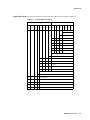
Table 3-4 shows the coding of the C-Block status word.
Table 3-4
C-Block status word contents
Bit no.
7
X
6
X
5
X
4
0
3
X
2
X
1
X
0
X
7
X
Usage
6
X
5
X
4
0
3
X
2
X
0
0
0
0
0
0
12
0
X
0
FMP disabled
1
FMP enabled
0
HR1 twin offset not active
1
HR1 twin offset active (+20bpm)
Reserved (zero)
Not used - currently set to zero
Reserved (zero to avoid <DLE>)
0
DECG logic off
1
DECG logic on
Reserved
Reserved (zero)
0
HR Cross Channel Verification not detected
1
HR Cross Channel Verification detected
0
Telemetry off
1
Telemetry on
0
Reserved
1
Reserved
0
FSpO2 not available (rev. A.02.00 or higher)
1
FSpO2 available (rev. A.02.00 or higher)
Remains (zero to avoid <DLE>)
0
No CTG data deleted
1
CTG data (250 msec ticks) deleted
0
No CTG data inserted
1
Default CTG data (250 msec ticks) inserted
0
Reserved (Monitor OFF)
1
Reserved (Monitor ON - M135X should set it to 1)
Data Block Overview
1
X
Data Blocks
C-Block Data with Heart rates and toco are transmitted 4 times per second (4 times in each C block). The heart
250ms Sample Rate rate is stored in 11 bits as an unsigned value. The value represents the range from 0 to 300
bpm (beats per minute), where 0 is identical to a "blank trace." The heart rate resolution is
0.25 bpm. Toco is stored for transmission in a single byte containing values from 0 to 127
with a resolution of 0.5 (stored as values from 0 to 200). These values are shown in
Table 3-5:
Table 3-5
C-Block: Storage of Heart Rate, Toco and FSpO2
Heart Rate
FSpO2
Toco
# bits used
11
8
8
Resolution
0.25 bpm
0.5
1
Digital Values
0 ... 1200
0 ... 255
0 ... 100
Represented Values
0,25... 300 bpm
0 ... 127
0 ... 100
Interpretation of 0
blank trace
-
-
Table 3-6 shows the coding of the first fetal heart rate (HR1).
Table 3-6
C-Block HR1 Coding
Bit no. /high byte
Bit no. / low byte
7
6
5
4
3
2
1
0
7
6
5
4
3
2
1
0
0
X
X
X
X
X
X
0
X
X
X
X
X
X
X
X
HR1 bits 10 ...0
0
0
1
FMP: 1= movement; 2, 3 = future (reserved)
0
0
Signal quality red
0
1
Signal quality yellow
1
0
Signal quality green
1
1
Reserved
Reserved (set to zero)
Data Block Overview
13
Data Blocks
The coding for the second fetal heart rate (HR2) and the maternal heart rate (MHR) is
identical to that of HR1, except that no fetal movement information is available for these
heart rates. Table 3-7 summarizes these heart rates:
Table 3-7
C-Block MHR and HR2 Coding
bit no./ high byte
bit no./ low byte
7
6
5
4
3
2
1
0
7
6
5
4
3
2
1
0
0
x
x
0
0
x
x
x
x
x
x
0
x
x
x
x
HR2 bits 10 ... 0
0
0
not used, set to zero
Signal Quality (see Table 3-6)
0
reserved, set to zero
The toco values are stored in single bytes and do not have any additional information
embedded, as shown in Table 3-8:
Table 3-8
C-Block Toco Coding
bit no.
7
6
5
4
3
2
1
0
x
x
x
x
x
x
x
x
Toco bits 7 ... 0
14
Data Block Overview
Data Blocks
C-Block HR - Mode The heart rate modes are stored in two bytes. The contents are shown in Table 3-9:
Table 3-9
C-Block HR-Mode Coding
Bit no. /High byte
7
X
6
X
5
X
4
0
3
X
2
X
Bit no. /Low byte
1
X
0
X
7
X
6
X
5
X
4
X
3
0
2
0
1
0
0
0
Reserved (zero)
MHR mode
1
inop
0
0
0
no transducer
0
1
1
MECG
1
0
0
Ext MHR
1
0
1
Reserved
1
1
0
Reserved
1
1
1
unknown mode
HR2 Mode
1
inop
0
0
0
no transducer
0
0
1
US
0
1
0
DECG
1
1
0
Reserved
1
1
1
Unknown mode
HR1 Mode
1
inop
0
0
0
no transducer
0
0
1
US
0
1
0
DECG
1
1
0
Reserved
1
1
1
Unknown Mode
Data Block Overview
15
Data Blocks
Table 3-10 summarizes the HR Mode codings.
Table 3-10 Heart Rate Modes Summary
Bit Code
Description
000
No Transducer
001
Ultrasound (US)
010
DECG
011
MECG
100
External MHR
101
Reserved
110
Reserved
111
Unknown Mode
C-Block Toco Mode The toco mode is stored in a single byte and contains the toco transducer type and mode. See
Table 3-11.
Table 3-11
7
0
C-Block Toco Mode Coding
6
0
5
0
4
0
3
X
2
X
1
X
0
0
Reserved
Toco mode
0
0
0
0
16
Data Block Overview
0
0
No transducer
1
0
0
Toco external
1
0
1
IUP
1
1
1
Unknown mode
Must be zero to avoid <DLE>
Reserved (zero)
Reserved (zero)
Reserved (zero)
0
Data Blocks
C-Block Fetal The FSpO2 measurement has a reserved byte in the standard CTG data block with protocol
Oxygen Saturation revision A.01.00. FSpO2 is transmitted only with Rev. A.02.00 or later (see page 17). The
use of this byte has been changed to include status information about the parameter.
Table 3-12 C-Block Toco Mode Coding
7
X
6
X
5
X
4
X
3
X
2
X
1
X
0
X
FSpO2 value 1% resolution. 0 = invalid (don’t print)
0
D6...D0 SpO2 value in percent, 1 unit resolution
1
D6 .. D0 future, to be defined
Table 3-13 M1351A/M1353A FSpO2 Resolution
Protocol Revision
FSpO2 Resolution
Revision A.01
Revision A.02
FSpO2 resolution 0.5%
D7=0: FSpO2 resolution 1%
D7=1: reserved
If rev. A.02 is available, FSpO2 is not transmitted if protocol is in A.01 (see below).
Protocol Revision Change Request ‘V’
The fetal monitor is programmed with the FSpO2 protocol revision A.01.01. To measure
FSpO2 you may need to request a protocol revision update (eg. to A.02.00). The system (eg.
OB TraceVue) can request an update of the fetal monitor protocol revision. The fetal
monitor then changes its protocol to the newest protocol available which may be equal to, or
older than, the requested protocol. If there is a new protocol, the fetal monitor should move
up to it to measure FSpO2. If there is no new protocol, it does not matter. See Table 3-13 for
a comparison of FSpO2 resolution across FSpO2 protocol revisions.
Note Before starting the new protocol, you should check whether the fetal monitor has accepted
the protocol change. You do this by requesting the ID Code. If the fetal monitor has changed
the protocol revision code, the system can start to communicate with the new protocol. If
not, there will be no response.
Data Block Overview
17
Data Blocks
Table 3-14 V-Block: Protocol Revision Change
‘V’
<byte1>
<byte2>
<byte1>
char
char
char
char
Example: <DLE><STX>’V’’A’’2’’0’<DLE><ETX><CRC><CRC>
Bytes 1 through 3 contain the requested protocol revision as in the ID message, for example,
“A20” corresponds to the Series 50 fetal monitor revision “A.02.00.”
Go In Auto Send Mode ‘G’
After power up, the fetal monitor does not automatically send CTG data. There are two ways
of initiating transmission of the CTG data:
1.
Request each CTG datablock by sending a request message with a ‘C’ as the data byte.
For full transmission of the CTG data, this must be done once per 900 -1100 msec.
2.
Let the fetal monitor send the CTG data automatically every second by issuing the ‘G’
command (sending a ‘G’ data block without any additional data).
The data code for G-mode (auto send mode) is:
<DLE><STX>G<DLE><ETX><CRC><CRC>
Which mode to use depends on the structure of the requesting software and hardware.
Under normal conditions, G mode is preferred.
On receipt of a ‘G’ command, the fetal monitor automatically sends a ‘C’ type block once
per second. This mode is canceled by a ‘H’ command or a ‘C’ request.
Halt Automatic CTG Transmission ‘H’
This command resets the auto send mode that was started by the ‘G’ command (see “Go In
Auto Send Mode ‘G’”). This command does not stop transmission of the data blocks for
event marking or nursing notes.
The data code for H-mode (hold-mode) is:
<DLE><STX>H<DLE><ETX><CRC><CRC>
18
Data Block Overview
Data Blocks
Event Message ‘MM’
Every time the event marker button of the Series 50 fetal monitor is pressed, an
asynchronous message "Event Message for Marker" data block is transmitted to the host
system. This also applies with the Remote Event Marker.
The Data Code for the Event Message Marker transmission is:
<DLE><STX>MM<DLE><ETX><CTC><CRC>
Note ‘N’
Nursing notes can be entered via a barcode reader which is connected to the fetal monitor
and these notes can be transmitted to the host system for storage purposes. The data code for
nursing notes is:
<DLE><STX>N<nul> <Text 1-28 characters><DLE><ETX><CRC><CRC>
Nursing notes can also be entered via the host PC and the transmitted to the fetal monitor
and printed on the CTG trace. This function can be used eg. to document the results of
external processing on the CTG trace. The data code for transmission in this direction is:
<DLE><STX>N<ID-L><ID><Text><DLE><ETX><CRC><CRC>
where ID-L is the number of characters used for the <ID> and <Text>. The <ID> is optional,
and if included it is printed in brackets on the recorder printout.
Thus the following transmission
<DLE><STX>N<02><PC><This is a note.>
appears on the trace as
{PC}This is a note.
The <ID> and <Text> cannot exceed 28 characters.
A note starts with a byte that tells how many characters are used for the user identification.
That byte can be zero; this means that the text note immediately follows that byte. There is
no additional separator between the user identification and the note text itself.
The Series 50 fetal monitors can annotate up to 3 notes at the same time and can keep an
additional 2 notes in its memory. Notes from the barcode reader have priority over those sent
from the host PC. Depending on paper speed and note length, the host PC may have to wait
several minutes before sending additional notes to be printed.
The fetal monitor ignores the notes in following cases:
n
The recorder is switched off
n
The recorder is out of paper
n
The recorder is in "paper advance mode"
n
The annotation buffer is full.
Data Block Overview
19
Data Blocks
The N data block has a variable length because the string length can vary from note to note.
The length limits are as follows:
n
29 characters for notes sent to the fetal monitor
n
510 characters for notes sent from the fetal monitor.
The length can be determined by the length of the transmitted block, i.e. by the surrounding
of the data block with <DLE><STX> and <DLE><ETX>. Thus, it includes the "user ID
length" byte and the user ID.
In other words, a system can send up to 28 printable characters (sum of length of user ID and
note text) to the fetal monitor. Additional characters are ignored by the fetal monitor.The
fetal monitor actually sends up to 30 printable characters and does not send an user ID. This
means that the user ID length byte is set to 0.
Failures ‘F’
If the fetal monitor detects a defect, the error coding is reported as 3 character ASCII text.
See the User’s Guide and Service Documentation for the fetal monitor for an explanation of
these codes. To transmit the error code "503," for example, the following sequence is sent:
<DLE><STX>F503<DLE><ETX><CRC><CRC>
If a fatal error occurs, the fetal monitor stops an ongoing data transmission. If possible, an
‘F’ block is sent to the system to report the problem.This behavior uses one of the features of
the link level protocol definition as described in The Data Link Layer on page 7: If a start of
block is recognized before an end of block was received, the incomplete block must be
discarded and the new block accepted.
Problems can occur if a transmitted message is interrupted directly after the <DLE><ETX>
sequence, that is, within the CRC bytes. These bytes are read without interpreting <DLE>
codes. The fetal monitor should send two arbitrary bytes that do not contain one of the
special characters described in The Data Link Layer on page 7, e.g. two zero-bytes. After
these two bytes a new block can be started and will be safely recognized.
After such a fatal error, the fetal monitor restarts and the connection between the fetal
monitor and the system must be built again.
20
Data Block Overview
Data Blocks
ID-Code ‘I’
The fetal monitor ID-Code can be requested by the system and is also used at startup to
identify the fetal monitor.
It contains a 6 character ID code, the 3 character protocol revision number, the fetal monitor
software revision and fetal monitor serial number. Future enhancements to the protocol are
possible by changing the protocol revision in the ID-code.
Table 3-15 shows the structure of the ‘I’ data block.
Table 3-15 I-Block: Identify Monitor and Protocol
Byte
Contents
1 ... 6
ID Code, e.g. “M1350A”
7 ... 9
Protocol revision
10 ...16
Fetal Monitor Software revision (e.g. A.01.01)
17 ... 26
Serial Number of the Monitor (10 chars, e.g. “3019G10010”)
The protocol revision name described in this document is, for example, "A30". This is
similar to Philips’ recommendation on use of revision numbers for medical products, except
that the second and third part of that number only has a single digit and there are no ‘.’
characters. The corresponding revision is A.03.00.
The fetal monitor software revision is coded to correspond to the HSG nomenclature, for
example, "A.03.00".
Maternal (NIBP) ‘P’
NIBP stands for Non Invasive Blood Pressure and is a value that is sent in non-regular form,
or with a sampling rate of once per some minutes. NIBP values are transferred in a block of
4 words as shown in Table 3-16. A NIBP value of 100 stands for 100 mm/Hg. The heart rate
is the maternal heart rate. It has a resolution of 0.25 bpm as it is defined for the continuously
measured heart rate from the fetal monitor.
The heart rate may have two special values:
0000H
The HR is invalid, but the device is able to measure the maternal heart rate.
FFFFH
The NIBP-device is not able to measure the HR and thus it is invalid.
Data Block Overview
21
Data Blocks
Table 3-16 P-Block: Maternal Non-Invasive Blood Pressure
Byte
Contents
1 ... 2
Systolic Blood pressure
3 ... 4
Diastolic Blood pressure
5 ... 6
Mean Blood pressure
7 ... 8
NIBP’s Maternal Heart rate
Maternal Temperature ‘T’
This data block contains the maternal temperature in degrees Celsius. See Table 3-17 for the
coding. The temperature has a resolution of 0.1 ºC and an offset of 25 ºC.
Thus, the values are in the range of 25.0 ºC to 50.5 ºC.
Table 3-17 T-Block: Maternal Temperature
‘T’
<Temp>
char
u_8
Maternal Oxygen Saturation ‘S’
The maternal oxygen saturation is coded as described in Table 3-18 for the CTG datablock,
i.e. values in the range from 0 to 200 represent values from 0% to 100% with 0.5%
resolution. The block also contains a maternal heart rate that is delivered by the SpO2
device. This heart rate has a resolution of 0.25 bpm as it is defined for the C-datablock and
NIBP-datablock (see also the previous section for an explanation of the values 0000H and
FFFFH).
Table 3-18 S-Block: Maternal Oxygen Saturation
22
‘S’
<Oxygen Saturation>
<SpO2’s Maternal HR>
char
u_8
u_16
Data Block Overview
Troubleshooting
Troubleshooting
Time Synchronization
A “jitter” problem may occur if you are using the OBMS monitor in request mode, if the
clock governing the incoming CTG request and the fetal monitor’s internal clock are not
synchronous. It depends on the accuracy of the space in time between two incoming CTG
requests. In the worst case, at every clock tick data would be deleted and inserted in
alternation. To avoid this, the accuracy of the time between two requests must be specified
as described below:
n
Incoming CTG requests at the fetal monitor must arrive once per second to receive
all the data. The time between two requests must not exceed 1100 msec and must
not be less than 900ms.
n
The fetal monitor must have a buffer for the internal CTG data (with a sample rate
of 4 values per second) to delay the insertion/deletion process. This buffer should
hold data of at least 500 msec, i.e. two samples. If insertions are necessary, they can
be done using the additionally buffered data, and no dummy data needs to be
created. For deletions there is no change in the algorithm.
This additional buffer can cause an additional delay of the CTG data of 500 msec.
Data Block Overview
23
Troubleshooting
24
Data Block Overview
4
The CRC Mechanism
Introduction
The term CRC stands for "Cyclic Redundancy Check." This is a checksum that is appended
to a datablock to detect errors in the transmission. The checksum given below is provided as
an example only; it is taken from the literature listed in the footnote below. It is neither
guaranteed nor supported by Philips.
Using a checksum to detect errors
Using this checksum, the following types of errors can be detected1:
n
100% of single-bit errors
n
100% of double-bit errors
n
100% of odd-numbered errors
n
100% of burst errors, where the burst is shorter than 16 bits
n
99.9969% of burst errors of exactly 17 bits
n
99.9984% of all other burst errors.
The CRC is calculated using a polynomial division (the CRC is the remainder of that). The
polynomial used is the same as that defined by CCITT2:
The information bits, taken together, correspond to the coefficients of a message polynomial
having terms from Xn-1(n = total number of bits in a block or sequence) down to X16. This
polynomial is divided, modulus 2, by the generating polynomial X16+X12+X5+1. The check
bits correspond to the coefficients of the term X15 to X0 in the remainder polynomial found
at the completion of this division.
This polynomial is widely used, e.g. in the XMODEM and HDLC/SDLC protocols. This 16bit remainder is the CRC-word appended to a message. There are two ways to check the
message for correctness:
n
Calculate the CRC for the message and compare the result with the appended CRC.
The result must be equal.
n
Calculate the CRC over the complete message including the CRC sent with that
message. The result must be zero!
1. Tannenbaum, Andrew S., Computer Networks, Prentice-Hall, 1981.
2. The CCITT Red Book, Volume VIII, International Telecommunications Union,
Geneva, 1986. Recommendation V.41, "Code-Independent Error Control System."
The CRC Mechanism
25
Using a checksum to detect errors
The CRC creation and check can be efficiently carried out using a lookup table. The
following lists the two functions used to create that lookup table and to calculate a CRC
using the table:
/**************************************************************************
* crcfuncs.c
*
* This module contains the functions mk_crctbl to create a CRC lookup
* table and crcupdate to calculate a CRC. These functions are listed and
* explained in: Joe Campbell: C Programmer’s Guide to Serial Communications,
*
Howard W.Sams & Company, 1987
* This implementation is a slightly modification of that publication.
**************************************************************************/
#include <stdlib.h>
static unsigned short crctab[256];/* The CRC lookup table */
#define GENERATE_POLYNOMIAL 0x1021/* The CCITT polynomial */
/*-----------------------------------------------------------------------* crcupdate ( unsigned short data,
---
new data to be added to CRC
*
---
storage of old/new CRC
unsigned short *accum
*
)
*/
void crcupdate ( unsigned short data, unsigned short *accum )
{
*accum = (*accum << 8) ^ crctab[(*accum >> 8) ^ data];
}
/*-----------------------------------------------------------------------* crchware ( unsigned short data,
--- data to be polynomial divided
*
unsigned short poly,
--- polynomial divisor
*
unsigned short accum
--- old (preset) CRC value
*/
26
The CRC Mechanism
Using a checksum to detect errors
static unsigned short crchware ( unsigned short data,
unsigned short poly,
unsigned short accum )
{
int i;
data <<= 8;
/* Data to high byte */
for (i=8; i>0; i--)
{
if ((data ^ accum) & 0x8000)
/* if msb of (data XOR accum) is TRUE
*/
accum = (accum << 1) ^ poly;
/* shift and subtract poly */
else accum <<= 1;
/* otherwise, transparent shift */
data <<= 1;
/* move up next bit for XOR */
}
return accum;
}
/*-----------------------------------------------------------------------* mk_crctbl ()
---
Creates / fills the crctab table
*/
void mk_crctbl ( void )
{
int i;
for (i=0; i<256; ++i)
{
/* Fill the table with CRCs of values .... */
crctab[i] = crchware ( i, GENERATE_POLYNOMIAL, 0 );
}
The CRC Mechanism
27
Using a checksum to detect errors
The function mk_crctb must be called first to initialize the CRC table crc_tab. The CRC
for a data block can be achieved by subsequently using the crcupdate function for each byte
of the data block. For the first byte, the accum variable must have the value 0 (zero). The
following is an example of the usage for that module:
static void testcrc ( void )
{
unsigned short crc;
int i;
char *message = “Check this message!”;
mk_crctbl();
/* This must be called only once in an application */
crc = 0;
/* Initialize the CRC value with zero */
for ( i=0; i<strlen(message); ++i )
{
crcupdate ( message[i], &crc );
}
printf ( “Message=<%s>, CRC=%04x\n”, message, crc );
}
When running this program, the result should be:
Message=<Check this message!>, CRC=9e8f
28
The CRC Mechanism
5
Programming Example
Digital data exchange example
This chapter contains a programming example to demonstrate the digital data exchange
between the fetal monitor and a PC. This example program is for demonstration purposes
only. assumes no responsibility for the contents, application or reliability of this program
listing.
/************************************************************************
*
Program PCDEMO Rev. A.01.01
* CONTENTS:
*
Demoprogram for digital-PC communication between M135X and a PC.
*
The connected Monitor is set to Auto Send Mode and the incoming data
*
is displayed on the screen. Only the latest samples are displayed.
*
The serial port can be selected in the commandline by entering
*
*
PCdemo /1..4
*
*
Compiling:
*
This example program has been compiled with a MS-C 6.0 compiler (or
equivalent)
*
using the medium memory model.
*
Commandline for compiling :
*
*
cl /AM /Oi /Gs pcdemo.c comctrl.lib graphics.lib
*
*
An additional non standard C library is used for serial communica-
*
tion routines. ( m_comctr.lib )
*
If you don’t want to use this library, you should replace the
*
functions InitCom, ResetCom, WriteCom and ReadCom and remove
*
the line #include <comctrl.h> and replace it with an equivalent.
*
************************************************************************/
/* redefine data types for readability */
#define u_8
unsigned char
/*
one byte */
#define u_16
unsigned short
/*
one word */
#define i_8
char
Programming Example
29
Digital data exchange example
#define i_16
short
/*-SYSTEM INCLUDES-----------------------------------------------------*/
#include <stdio.h>
#include <string.h>
#include <conio.h>
#include <graph.h>
#include "comctrl.h"
/* Header for m_comctr.lib library */
/*-GLOBAL FUNCTIONS----------------------------------------------------*/
u_16 CRC( u_16 Data );
void UpdateCRC(u_8 c, u_16 *chks);
u_16 DllRxD( u_8 *dbuff,u_16 dlen, u_8 byte );
u_16 DllTxD( u_8 *dbuff,u_8 *pbuff, u_16 len );
u_16 InitPort( void );
u_16 ReadPort( u_8 *Buffer );
u_16 WritePort( u_8 *Buffer, u_16 Number);
/*-GLOBAL VARIABLES----------------------------------------------------*/
static u_8
Port = 0;/* number of the serialport 0=COM1 1=COM2 ... */
/*-CONSTANTS (DEFINES)-------------------------------------------------*/
/* Ascii characters used for package framing */
#define
DLE
0x10
#define
STX
0x02
#define
ETX
0x03
#define
SYN
0x16
/* Internal states for the receiving state machine */
30
#define
RXD_WAITDLE
0
#define
RXD_WAITSTX
1
#define
RXD_DATA
2
#define
RXD_DLE
3
#define
RXD_WAITCRC1
4
#define
RXD_WAITCRC2
5
Programming Example
Digital data exchange example
/* The CCITT polynomial */
#define
GENERATE_POLYNOMIAL
0x1021
/************************************************************************
* FUNCTION:Savebyte
*************************************************************************
* DESCRIPTION:
*
Saves a byte to a buffer
*************************************************************************
* INPUT/OUTPUT PARAMETERS
* Name
Type
i/o
Comment
* ---------------------------------------------------------------------**
*
*p
u_8
i
pointer to bufferbase
*
**wpp
u_8
i/o
*
bytesize
u_16
i
size of buffer
*
byte
u_8
i
data to be stored in buffer
*
return
i_16
o
1 if buffer full, else 0
work pointer
************************************************************************/
static i_16 Savebyte(u_8 *p, u_8 **wpp, u_16 bytesize, u_8 byte)
{
/* Save byte in buffer and increment work ptr */
**wpp = byte;
*wpp += 1;
/* check if buffer is full */
if( (u_16)(*wpp - p) >= bytesize )
return(1); /* The currently used buffer is full */
else
return(0);
} /* end SaveByte */
/************************************************************************
* FUNCTION:CRC
*************************************************************************
* DESCRIPTION:
*
One step of calculating the crc .
*************************************************************************
Programming Example
31
Digital data exchange example
* INPUT/OUTPUT PARAMETERS
* Name
Type
i/o
Comment
* ---------------------------------------------------------------------**
* Data
u_16
i
data byte
* return
u_16
o
result of calculation
************************************************************************/
u_16 CRC( u_16 Data )
{
u_16
Accu = 0;
i_16
i;
Data <<=8;
for(i=8; i>0; i--)
{
if((Data^ Accu) & 0x8000 )
Accu = ( Accu << 1 ) ^ GENERATE_POLYNOMIAL ;
else
Accu <<= 1;
Data <<= 1;
} /* end for i ... */
return( Accu );
} /* end CRC */
/************************************************************************
* FUNCTION:UpdateCRC
*************************************************************************
* DESCRIPTION:
*
Updates the CRC byte by byte.
*************************************************************************
* INPUT/OUTPUT PARAMETERS
* Name
Type
i/o
Comment
* ---------------------------------------------------------------------**
* c
u_8
* *chks
u_16
i
i/o
character value to be added to crc
pointer to checksum storage
************************************************************************/
void UpdateCRC(u_8 c, u_16 *chks)
32
Programming Example
Digital data exchange example
{
u_16 bcc;
bcc = *chks;
bcc = (bcc << 8) ^ CRC(((bcc >> 8) ^ c) & 0xff) ;
*chks = bcc;
} /* end UpdateCRC */
/************************************************************************
* FUNCTION:DllRxD
*************************************************************************
* DESCRIPTION:
*
Unpacks a received datablock byte by byte. If a received message is
*
complete its length is returned. If the message is not complete 0 is
*
returned.
*************************************************************************
* INPUT/OUTPUT PARAMETERS
* Name
Type
i/o
Comment
* ---------------------------------------------------------------------**
* *dbuff
u_8
i
destination pointer
* dlen
u_16
i
max length of destination buffer
* byte
u_8
i
received databyte
* return
u_16
o
length of received datablock
************************************************************************/
u_16 DllRxD( u_8 *dbuff,u_16 dlen, u_8 byte )
{
static u_8
state = RXD_WAITDLE;
static u_16
crc = 0;
static u_8
*wp = 0;
u_16
l;
switch(state)
{
case RXD_WAITDLE:
/* wait for DLE
*/
if (byte==DLE)
{
Programming Example
33
Digital data exchange example
state = RXD_WAITSTX;
UpdateCRC(byte, &crc);
}
break;
case RXD_WAITSTX:
/* wait for start of text (STX)
*/
if (byte==STX)
{
state = RXD_DATA;
UpdateCRC(byte, &crc);
wp = dbuff;
/* Set work ptr to start of buffer */
}
else
{
state=RXD_WAITDLE;
crc = 0;
}
break;
case RXD_DATA:
/* read data
*/
/* Calc checksum for each byte */
UpdateCRC(byte, &crc);
if( byte == DLE )
/* get rid of doubled DLE in data block */
{
state = RXD_DLE;
break;
}
else
{
if( Savebyte(dbuff, &wp, dlen, byte) > 0 )
{
/* The buffer limit is exceeded --> Discharge package */
/* Start over again */
state = RXD_WAITDLE;
break;
34
Programming Example
Digital data exchange example
}
}
break;
case RXD_DLE:
switch ( byte )
{
case DLE:
if( Savebyte(dbuff, &wp, dlen, byte) > 0 )
{
/* The buffer limit is exceeded --> Discharge package */
/* Start over again */
state = RXD_WAITDLE;
break;
}
state = RXD_DATA;
UpdateCRC(byte,&crc);
break;
case ETX:
state = RXD_WAITCRC1;
UpdateCRC(byte,&crc);
break;
case STX: /* This is already the start of a new package */
crc = 0;
UpdateCRC(DLE, &crc);
UpdateCRC(STX, &crc);
state =
RXD_DATA;
wp = dbuff;
/* Set work ptr to start of buffer */
break;
default:
/* Invalid char after DLE -> Sequence error, discharge package
*
crc = 0;
Programming Example
35
Digital data exchange example
state = RXD_WAITDLE;
break;
} /* switch(byte) */
break;
case RXD_WAITCRC1:
/* This byte is treated as the first byte of the checksum */
UpdateCRC(byte, &crc);
state = RXD_WAITCRC2;
break;
case RXD_WAITCRC2:
/* This byte is treated as the second checksum byte */
UpdateCRC(byte, &crc);
/* Test crc */
if( crc )
{
/* CRC invalid -> Discharge package, reset crc accu */
crc = 0;
l = 0;
}
else
{
/* CRC ok */
/* Number of valid bytes in buffer */
l =
wp - dbuff;
}
state = RXD_WAITDLE;
return(l);
break;
} /* switch(*state) */
return(0);
} /* end DllRxD */
/************************************************************************
36
Programming Example
Digital data exchange example
* FUNCTION:DllTxD
*************************************************************************
* DESCRIPTION:
*
A entered datablock is packed into the datalink layer which means
*
that a DLE STX is added at the beginning of the block.
*
DLEs in the datablock are doubled.
*
A DLE ETX and the crc is appended at the end of the block.
*
-> DLE STX DataBlock DLE ETX CRC CRC
*************************************************************************
* INPUT/OUTPUT PARAMETERS
* Name
Type
i/o
Comment
* ---------------------------------------------------------------------**
* *dbuff
u_8
i
destination pointer
* *pbuff
u_8
i
source pointer
* len
u_16
i
number of bytes in dbuf
* return
u_16
o
length of pbuf
************************************************************************/
u_16 DllTxD( u_8 *dbuff,u_8 *pbuff, u_16 len )
{
u_8
byte;
u_16 i;
u_16 crc = 0; /* Current CRC value */
u_16 n;
/* Index of next free byte in dbuff */
/* Package header */
UpdateCRC(dbuff[n=0] = DLE, &crc);
UpdateCRC(dbuff[++n] = STX, &crc);
for( i= 0; i< len; i++)
{
byte = *pbuff++;
UpdateCRC(dbuff[++n] = byte, &crc);
if( byte == DLE )
UpdateCRC(dbuff[++n] =
DLE, &crc);
}
/* Add trailer */
Programming Example
37
Digital data exchange example
UpdateCRC(dbuff[++n] = DLE, &crc);
UpdateCRC(dbuff[++n] = ETX, &crc);
/* Add CRC */
dbuff[++n] = (u_8)((crc >> 8) & 0xff); /* CRC High byte */
dbuff[++n] = (u_8)( crc & 0xff );
/*
Low
*/
return(++n);
/* Add blkno for that package */
} /* end DllTxD */
/************************************************************************
* FUNCTION:InitPort
*************************************************************************
* DESCRIPTION:
*
Initializes a serialport to
*
*
1200 Baud/no parity/8 bit data/1 stop bit
If failed a non zero value is returned, else 0.
*************************************************************************
* INPUT/OUTPUT PARAMETERS
* Name
Type
i/o
Comment
* ---------------------------------------------------------------------**
* return
u_16
o
0 if init OK else non 0
************************************************************************/
u_16 InitPort( void )
{
return( InitCom( Port,_C_CHR8|_C_STOP1|_C_NOPARITY ,_C_1200,512,0 ));
} /* end InitPort */
/************************************************************************
* FUNCTION:ReadPort
*************************************************************************
* DESCRIPTION:
38
*
Reads a message from the RS-422.
*
Every byte that is read from the interface is checked by the DLL.
*
If the routine DllRxD detects that a message is complete the length
*
of it is returned. If a message is incomplete 0 is returned.
Programming Example
Digital data exchange example
*
If there is no data in the receive buffer the routine ReadCom returns
*
0.
*************************************************************************
* INPUT/OUTPUT PARAMETERS
* Name
Type
i/o
Comment
* ---------------------------------------------------------------------**
* *Buffer
u_8
i
destination pointer
* return
u_16
o
length of received datablock
************************************************************************/
u_16 ReadPort( u_8 *Buffer )
{
static u_8 RBuffer[512];
u_8
byte;
u_16
DataLen = 0;
/* read data until a message is complete or receive buffer empty*/
while( ReadCom( Port,&byte,1) &&
!(DataLen = DllRxD( RBuffer,512, byte )));
/* if a message is complete copy message from receive buffer to buffer */
if( DataLen )
memcpy( Buffer, RBuffer,DataLen );
return( DataLen );
} /* end ReadPort */
/************************************************************************
* FUNCTION:WritePort
*************************************************************************
* DESCRIPTION:
*
Sends data via the DLL and the RS-422. Data is first packaged by
*
the routine DllTxD.
*
The packaged data ( DLE STX Data DLE ETX CRC CRC ) is stored in
*
XBuffer. The number of bytes to send is returned by the routine
*
DllTxD.
*************************************************************************
* INPUT/OUTPUT PARAMETERS
* Name
Type
i/o
Comment
Programming Example
39
Digital data exchange example
* ---------------------------------------------------------------------**
* *Buffer
u_8
i
source pointer
* Number
u_16
i
number of databytes to send
* return
u_16
o
0 if OK else non 0
************************************************************************/
u_16 WritePort( u_8 *Buffer, u_16 Number)
{
u_8 XBuffer[80];
Number = DllTxD( XBuffer,Buffer,Number);
return( WriteCom( Port, XBuffer, Number));
} /* end WritePort */
/************************************************************************
* FUNCTION:main
*************************************************************************
* DESCRIPTION:
*
main program.
*************************************************************************/
void main( i_16 argc, u_8 *argv[] )
{
u_8
Data[512]; /* Data buffer */
i_16
i;
_clearscreen(_GCLEARSCREEN);
for(i=1;i<=argc;i++)
if( *argv[i]==’/’) Port =(u_8) (argv[i][1]-49) ;
if( Port > 3 ) Port = 0;
InitPort();
/* make sure that no invalid port can be used */
/* init serial port */
_settextposition( 1,18);printf("********
REV A.01.01
**********");
_settextposition( 2,18);printf("*DEMO PROGRAM for DIGITAL PC INTERFACE *");
_settextposition( 3,18);printf("****************************************");
_settextposition( 4,18);printf("*
Port COM%d active
*",
Port+1 );
_settextposition( 5,18);printf("*
40
Programming Example
Auto Send Mode active
*");
Digital data exchange example
_settextposition( 6,18);printf("*
Press any key to abort
*");
_settextposition( 7,18);printf("****************************************");
_settextposition( 8,18);printf("* received data ( only latest sample )
*");
_settextposition( 9,18);printf("************************************");
_settextposition(10,18);printf("*
*");
_settextposition(11,18);printf("********* **************************");
WritePort("G",1 );
/* start Auto Send Mode
*/
while ( !kbhit() )
if( ReadPort( Data ) )
/* if a message is complete */
if( *Data == ’C’ )
/* check if it is a C-Block */
{
_settextposition(10,20);
printf("HR1 %6.2f
HR2 %6.2f
TOCO %6.2f",
(float)( (Data[4]+((Data[3]&0x07)<<8) ) /4),
/* heartrate 1 */
(float)( (Data[12]+((Data[11]&0x07)<<8) ) /4),/* heartrate 2 */
(float)( Data[27]/2));
/* toco
*/
} /* end if () */
WritePort("H",1 );
/* stop Auto Send Mode */
i=0;while(i++);
/* wait ...
*/
_settextposition(13,18);printf("Program aborted by user \n");
ResetCom( Port );
/* reset serial port */
} /* end main */
Programming Example
41
Digital data exchange example
42
Programming Example
A
Glossary
Antepartum: Occurring before birth.
Artifact: Irregularities on a fetal monitor trace caused e.g. by poor signal reception.
Coincidence: Describes the detection of identical heartrates. If two heartrates,e.g. maternal
and first fetal heartrates, have the same values over a defined time, then these two heartrates
are said to coincide. This can happen for example if both transducers are picking up the
same heartrate signal.
ECG: Electrocardiogram.
DECG: Direct Electrocardiogram.
DECG Arrhythmia Logic: This enables or disables a postprocessor of the acquisition in
the fetal monitor that suppresses artifacts (see above). If the patient might have arrhythmia,
the logic function should be disable to enable arrhythmia monitoring.
External MHR: Input by an external device, e.g. an external SpO2 device.
External Parameter: The Series 50 fetal monitors and also the HP 8040 fetal monitors
have an external parameter input. The external signal produced is printed on the strip chart
either on the heartrate or the toco grid.
Fetal Movement: See FMP.
FHR: Fetal Heart Rate.
FMP: Fetal Movement Profile: When fetal movement is detected by a Series 50 fetal
monitor, a box is printed on the upper part of the Toco grid on the fetal trace.
Intrapartum: Occurring during birth.
IUP: Intrauterine Pressure
NOP: Inoperable/ no operation.
MECG: Maternal Electrocardiogram.
NIBP: Noninvasive Blood Pressure. That has three values: systolic pressure, diastolic
pressure, and mean pressure. The mean values is calculated so that it splits the area under the
pressure curves exactly half by half. The mean value is not the arithmetic or geometric mean
of the systolic and diastolic pressure.
SpO2: The saturation of oxygen in the blood is given as a percentage value.
Signal Quality: This is represented by the colored output on the front panel of the fetal
monitor. There is a red, green, and yellow lamp to show a good or bad signal quality. This
can help the nurse to position the transducers to optimize the signal reception.
Toco: Toco transducer, a pressure-sensing device used to record uterine activity
Ultrasound (US): Use of high-frequency sound to measure movement, for example closure
of fetal heart valves, to monitor fetal heart rate.
A-1
A-2