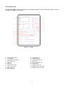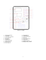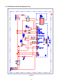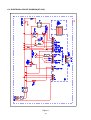
1
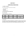
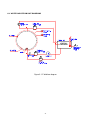
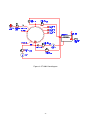
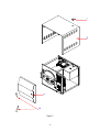
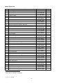
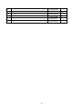
NÜVE SANAYİ MALZEMELERİ İMALAT VE TİCARET A.Ş.
BENCH TOP STEAM STERILIZERS
OT 020 / OT 020V
SERVICE MANUAL
CONTENTS
SECTION 1 INTRODUCTION
1.1. Purpose of the Service Manual
1.2. General Purpose
2
3
SECTION 2 OPERATING PRINCIPLES
2.1. General Overview
2.2. Explanations of Functions
2.2.1. Power Supply Values
2.2.2. Main PCB
2.2.3. Clontrol Panel
2.2.4. Water and Steam Unit
4
4
4
4
5
7
SECTION 3 SERVICING
3.1. General Overview
3.2. General Failure
3.3. Temperature Control Failure
8
9
11
SECTION 4 CALIBRATION PROCEDURE
13
4.1. How to Measure the Actual Temperature
4.2. Calibration
4.2.1. OT 020
4.2.2. OT 020 V
13
13
13
13
SECTION 5 SPARE PART REPLACING
4.1. Access to Command and Control
4.2. Replacing Main PCB
4.3. Replacing Display PCB
4.4. Replacing Temperature Sensor
4.5. Replacing Condense Selonoid Valve
4.6. Replacing Water Filling Solenoid Valve
4.7. Replacing Steam Discharge Solenoid Valve
4.8. Replacing Vacuum Line Solenoid Valve
4.9. Replacing Check Valve
4.10. Replacing Vacuum Pump
4.11. Replacing Water Pump
4.12. Replacing Safety Valve
4.13. Replacing Water Level Sensor
4.14. Replacing Heater
4.15. Replacing Plastic Panel
4.16. Replacing Locking Bobbin
4.17. Replacing Locking Switch
4.18. Cleaning the Sterilizator Chamber Filter
4.19. Replacing Pressure Switch
14
14
14
14
14
15
15
15
15
15
16
16
16
16
16
17
17
17
17
SECTION 6 DRAWINGS AND DIAGRAMS
6.1. Electric Circuit Diagram (OT 020)
6.2. Electrical Circuit Diagram (OT 020V)
6.3. Water and Steam Unit Diagrams
19
20
21
SECTION 7 SPARE PART LIST
Spare Parts List
29
1
SECTION 1
INTRODUCTION
1.1. PURPOSE OF THE SERVICE MANUAL
This manual includes servicing and maintenance information for OT 020 and OT 020V Bench Top
Steam Sterilizers. It is prepared to be used by technicians who were formerly trained by Nuve. This
manual informs the technicians about the operating principles, diagnosing and repairing methods and
spare part replacing.
If any problem determined which is not identified in this manual, please contact to Nuve Servicing
Team.
Factory
Esenboğa Yolu 22 km
Akyurt - ANKARA / TURKEY
Tel : (00 90 312) 399 28 30 ( 3 lines )
Fax : (00 90 312) 399 21 97
e-mail: [email protected]
2
1.2. GENERAL PURPOSE
The heating function is provided by means of the stainless heater placed inside the sterilization
chamber. The sterilization cycle consists of the water filling, heating, sterilization, steam discharge and
drying phases.
Water filling: Distilled water is taken from the distilled water tank and pumped into the sterilization
chamber by means of a vacuum pump.
Heating: The distilled water in the sterilization chamber is heated to generate steam at the required
temperature and pressure. During heating, the condense solenoid valve is opened and discharges the
unsaturated steam periodically.
Sterilization: When the sterilization chamber temperature reaches the set temperature sterilization
starts. The sterilization chamber is kept at the required temperature and pressure during the set time.
During sterilization, the condense solenoid valve keeps the pressure in the chamber constant
according to the set temperature.
Steam discharge and drying (OT 020): During the steam discharge phase, the steam in the
sterilization chamber is discharged and after the pressure has dropped to zero, moisture in the
sterilizator chamber is discharged according to driying time set on the OT 020.
Steam discharge and drying (OT 020V): During the steam discharge phase, the steam in the
sterilization chamber is discharged and after the pressure has dropped to zero, the vacuum pump is
operated for drying. During drying, the air intake is ensured by opening the air intake solenoid valve
and taking in fresh air after it has been passed through 0,2 µm biological filter.
3
SECTION 2
OPERATING PRINCIPLES
2.1. GENERAL OVERVIEW
The OT 020 and OT 020V can be split into 4 main groups,
•
•
•
•
Power supply values
Control unit
Heating unit
Water and steam unit
2.2. EXPLANATIONS FOR THE FUNCTIONS
2.2.1. Power Supply
The power supply values are listed below.
Glass Fuse
Power Supply
Power inlet
Heater Supply
OT 020
10 A
1500 W
230 V, 50 Hz
OT 020V
10 A
1550 W
230 V, 50 Hz
Stainless tube type
(1450 W)
Stainless tube type
(1450 W)
2.2.2. Main PCB
The microprocessor controlled main PCB operates on “proportional” heating system. The main PCB
first prepares steam at the required temperature and pressure in the sterilization chamber. Then, it
carries out the sterilization, steam discharge and drying phases as explained in the section 1.2 At the
end of the phases, the sterilizer warns the users with an audible alarm that the cycle has ended.
4
2.2.3. Control Panel
The illustration below shows the functions of the display board. For more information, please see the
OT 020 or OT 020V user’s manual.
Figure 1- OT 020
1.
2.
3.
4.
5.
6.
7.
8.
9.
10.
Temperature display
Time display
Temperature setting key
Time setting key
Start key
Stop key
Value decrease key
Value increase key
Alarm mute key
Water filling led
11.
12.
13.
14.
15.
16.
17.
18.
19.
5
Preperation led
Sterilization led
Steam discharge led
Drying led
Cycle completed led
Lid open led
Overpressure led
Maximum water level led
Minimum water level led
Figure 2- OT 020V
1.
2.
3.
4.
5.
6.
7.
8.
9.
10.
Temperature display
Time display
Temperature setting key
Time setting key
Drying time
Start/Stop key
Value decrease key
Value increase key
Alarm mute key
Water filling led
11.
12.
13.
14.
15.
16.
17.
18.
19.
6
Preperation led
Sterilization led
Steam discharge led
Drying led
Cycle completed led
Lid open led
Overpressure led
Maximum water level led
Minimum water level led
2.2.4. Water and Steam Unit
The steam needed for the sterilization is generated by boiling the distilled water which is taken from the
water tank to the sterilization chamber.
The pressure in the sterilization chamber is followed on the manometer.
The steam charge, steam discharge, air intake♣, condense and vacuum line solenoid valves♣ are
operated as explained in the section 1.2 by the main PCB.
The sterilization chamber safety valve operates if the pressure inside the chamber exceeds 3,5 Bar and
it discharges the excess steam which leads to over-pressure.
The maximum pressure switch cuts the power of heaters when the pressure inside the chamber
exceeds 3 bar to protect the device and user. The minimum pressure switch also prevents door to open
if there is a pressure other than zero (over zero) in the chamber after the sterilization cycle and
provides safe operation. The second minimum pressure switch equipped in OT 020V is used to start
the vacuum pump after the pressure inside the sterilizator chamber drops to zero.
The components of the water and steam unit are listed below,
•
•
•
•
•
•
•
•
•
•
♣
Reserve tank
Manometer
Water charge solenoid valve
Steam discharge solenoid valve
Condense solenoid valve
Vacuum line solenoid valve♣
Water pump
Vacuum pump♣
Check valve
Sterilization chamber safety valve (3,5 Bar)
This feature is valid for only OT 020V.
7
SECTION 3
SERVICING
Caution: Before servicing the instrument, please take the necessary precautions for your
health. Please respect to the warnings on the unit!!
Please make sure that you have disconnected the unit before you service it.
3.1. GENERAL OVERVIEW
The failures can be diagnosed according to the following tables.
Most of the arising problems can be determined by the help of a multimeter.
The components on the main PCB must not be replaced even the failure is caused by one of the
components on the main PCB. In this case, please send the failed PCB to factory service along with a
note on which the failure explanations are written.
Before replacing the PCB or any control element, please make sure that the failure is not caused by
weak wire and terminal connections.
8
3.2. GENERAL FAILURES
FAILURE
1 The on / off switch is ON
but it does not lighten,
the display is blank.
2 The on / off switch is ON
and lightens but the
display is blank or some
segments do not lighten.
3
The on / off switch is
OFF but it lightens.
PROBABLE CAUSES
Power supply inlet failure
SOLUTION
Check that mains voltage is supplied to the unit.
Check that the terminal connections and power
supply socket connections are well connected.
The glass fuse is blown.
Replace the glass fuse and check the short
circuit that causes the blowing of the fuse.
The main PCB / display PCB
connection cable is not
well connected.
Disconnect the connection cable and re-connect
it carefully.
The cable with socket is
defective.
Replace the cable.
The display PCB is defective.
Replace the display PCB.
The main PCB is defective.
Replace the main PCB.
The on / off switch cable
connections are connected in
reverse.
Check the connections and correct them.
4 The fuse blows frequently. Short circuit exists.
Check the heater with a multimeter. If shortcircuit
exists, replace the heater.
Check all solenoid valve bobbins for short-circuit
with a multimeter. If short-circuit exits in any
bobbin, replace it.
Check the vacuum pump♣ and water pump for
short-circuit. If there is short-circuit, replace that
pump.
Check all other electrical terminals and cables
for short-circuit.
5
♣
The pressure in the
The safety valve is open.
sterilization chamber does
not increase.
One of the steam charge,
condense or vacuum line solenoid
valves♣ is open or defective.
Close the valve by turning it to the counter
clockwise direction.
Take the capsule of the solenoid valve out and
clean the core of it. If you cannot solve the
problem replace the solenoid valve.
The heater is defective.
Check the heater. Replace it if it is defective.
The safety thermostat does not
outlet for heating.
Check with a multimeter that there is short circuit
in the safety thermostat terminals. If there is
no short-circuit, replace the safety thermostat.
This feature is valid only for OT 020V.
9
FAILURE
6 The lid leaks steam.
7
The steam sterilizer does
not discharge the steam
in the chamber.
PROBABLE CAUSES
The main PCB SSR relay does
not outlet.
SOLUTION
Check the outlet with a multimeter. If there is no
(12 VCD) outlet, replace the main PCB.
The SSR is defective.
Replace the SSR.
The lid gasket does not fit well
to the canal.
Adjust the gasket length to make it fit properly.
The gasket is crushed or torn.
Replace the gasket.
The adjustment of the lid is not
good.
Tighten the lid adjustment screw (15) by turning
it to the clock wise direction.
The main PCB discharge relay
is defective.
Check the steam discharge relay outlet with a
multimeter. If there is no outlet, replace the main
PCB.
The filter on the chamber inlet is
clogged.
Take the filter out and clean it.
The steam discharge solenoid is
defective.
Take the capsule of the solenoid out and clean
the core of it, if it doesn’t solve the problem
replace the solenoid valve.
8♣ The steam sterilizer stays The air intake selonoid is defective Take the capsule of the solenoid out and clean
under vacuum after the
the core of it, if it doesn’t solve the problem
replace the solenoid valve.
operation.
The biological filter is clogged.
9
The lid is not locked when The locking mechanism is
the steam sterilizer
defective.
starts operating.
The locking bobbin is defective.
10 The lid lock pin is not
released even the
pressure in the chamber
drops to zero.
Check the locking mechanism.
Replace the locking bobbin.
The main PCB locking bobbin
relay does not outlet.
Check the main PCB locking bobbin with a
multimeter. If there is no outlet (12 VCD),
replace the main PCB.
The lid lock mechanism is
defective.
Check the whole mechanism.
The lid locking bobbin is
defective.
Replace the locking bobbin.
The main PCB locking bobbin
relay does not outlet.
Check the relay outlet. If there is no outlet
(12 VCD), replace the main PCB.
11 The samples are wet
There is an over-loading of
at the end of the operation samples.
The drying time is not sufficient♣.
♣
Replace the fiter.
This feature is valid only for OT 020V
10
Check the load of the samples. Please leave
space between the samples.
Increase the drying time while programming.
3.3. TEMPERATURE CONTROL FAILURES
1
FAILURE
The temperature does
not reach the set
temperature
PROBABLE CAUSES
The main PCB SSR terminal
does not outlet.
SOLUTION
Check the SSR terminal outlet with a
multimeter. If there is no outlet (12 VCD),
replace the main PCB.
The heater is defective.
Check the resistance values of the heater
with a multimeter. If the heater is defective,
replace it.
The safety thermostat does not Check that the terminals are short-circuited with
allow for heating.
a multimeter. If there is no short-circuit,
replace the safety thermostat.
2
3
The temperature
exceeds the set
temperature.
The error "LID OPEN”
lightens on the display.
The main PCB SSR terminal
outlets continuously.
Check the main PCB SSR terminal outlet with a
multimeter. If there is continuous outlet (12 VCD)
replace the main PCB.
There is short-circuit in the
heater connection cables.
Check the connection cables. If there is
short-circuit, correct it.
The SSR outlets continuously.
Check the SSR terminals. If there is
continuous outlet, replace the SSR.
The lid is forced to open
during the operation.
Repeat the sterilization operation
after the current operation has finished.
The lid locking switch is
defective.
Check the switch and replace it if it is
defective.
4
The error message “OFF” Power is cut during the
appears on the display.
operation.
Repeat the sterilization.
5
The error message "H01”
appears on the display.
Check whether the endings are connected well
to the main PCB. Connect them properly if
needed.
Temperature sensor endings
are broken or they are
connected to the main PCB
loosely.
Check whether the endings of the temperature
sensor are broken. Replace the TC1 if they are
broken.
6
The error message “H02”
appears on the display.
Electronical failure occured.
7
The error message "H03” The SSR terminal of the main
appears on the display and PCB outlets continuously.
“OVERPRESSURE” led
lightens.
There is short-circuit in the
heater connection cables.
The SSR outlets continuously.
11
Replace the main PCB.
Check the SSR terminal outlet with a multimeter.
If there is continuous outlet (12 VCD) replace the
main PCB.
Check the connection cables. If there is
short-circuit, correct it.
Check the SSR terminals. If there is
continuous outlet, replace the SSR.
FAILURE
PROBABLE CAUSES
SOLUTION
8
The error message "H04” The endings of the temperature Connect the endings to the main PCB
appears on the display.
sensor are connected in reverse. correctly.
9
The error message "H06” Water cannot be filled into the
appears on the display.
sterilizator chamber.
10 The error message "H07” The SSR terminal of the main
appears on the display.
PCB does not outlet.
Check the water pump, water charge solenoid
valve, check valve and filter. Replace the
defective one.
Check the SSR terminal outlet with a multimeter.
If there is no outlet (12 VCD), replace the main
PCB.
The SSR does not outlet.
Check the SSR terminals. Replace them
if there is no electricity pass.
The heater is defective.
Check the resistance values of the heater with a
multimeter. If the heater is defective, replace it.
The safety thermostat does not
outlet for heating.
Check with a multimeter whether the safety
thermostat terminals are short-circuit. If there is
no short-circuit, replace the safety thermostat.
12
SECTION 4
CALIBRATION PROCEDURE
4.1 HOW TO MEASURE THE ACTUAL TEMPERATURE
•
•
•
•
•
As the chamber is pressurized please use calibrated external measuring devices which are
independent of any cable (thermometer, data-logger, etc.).
Insert your measuring device on one of the shelves in the chamber.
Be sure that the sensor of your measuring device does not touch any metal part in the chamber.
Make the necessary adjustments and start the program.
If the temperature of the equipment and the temperature of the measuring device are different from
each other, please apply the calibration procedure as below:
4.2 CALIBRATION
4.2.1 OT 020 (Figure 1)
• Press “value increase and decrease keys” (7 &8) together continuously until you see “0” on the
temperature display and any value on the time display.
• Press “stop” (6) and pass to the 1st parameter and repeat this (press start-stop) until you reach to
the 8th parameter.
• At the 8th parameter press “stop” (6) continuously until you see “LC1” on the temperature display.
• Press “time set” (4) you first see “HC1” on the temperature display, press “time set” again this time
you see “LC2” on the temperature display, press “time set” again you see “HC2” on the temperature
display. For the last time press “time set” and you see “JC” on the time display.
• Press “stop” and change the value that appears on the time display according to the difference
between the equipment’s display and the external sensor.
If the set temperature is 121°C and the external sensor measures 123°C, increase the value, which
appears on the time display, by adding 2; if the set temperature is 121°C and the external sensor
measures 118°C, decrease the value, which appears on the time display, by subtracting 3 by using
“value increase or decrease keys” (7 &8).
• Press “stop” to return to stand-by mode.
4.2.2 OT 020 V (Figure 2)
• Press “value increase and decrease keys” (7 &8) together continuously until you see “0” on the
temperature display and any value on the time display.
• Press “start-stop” (6) and pass to the 1st parameter and repeat this (press start-stop) until you
reach to the 7th parameter.
• At the 7th parameter press “stop” (6) continuously until you see “LC1” on the temperature display.
• Press “time set” (4) you first see “HC1” on the temperature display, press “time set” again this time
you see “LC2” on the temperature display, press “time set” again you see “HC2” on the temperature
display. For the last time press “time set” and you see “JC” on the time display.
• Press “start-stop” (6) and change the value that appears on the time display according to the
difference between the equipment’s display and the external sensor.
If the set temperature is 121°C and the external sensor measures 123°C, increase the value, which
appears on the time display, by adding 2; if the set temperature is 121°C and the external sensor
measures 118°C, decrease the value, which appears on the time display, by subtracting 3 by using
“value increase or decrease keys” (7 &8).
• Press “start-stop” (6) to return to stand-by mode.
Caution: Do not change any other parameters!!!
13
SECTION 5
SPARE PART REPLACING
Cautions : Disconnect the steam sterilizer before replacing any component !
5.1. Access to the Command and Control Unit (See Figure-7)
•
•
Remove the water filling line record (1) on the top of the steam sterilizer.
Take the cover sheet (2) out after removing the screws on the right and left sides of the steam
sterilizer.
5.2. Replacing Main PCB ( see Figure 8 & Figure 10)
•
•
•
•
•
Disconnect all cable terminals which are connected to main PCB clamps.
Disconnect the main PCB (7) - display PCB (31) connection cable from the main PCB.
Remove the 6 fixing screws of the main PCB and take the main PCB out.
Place the new main PCB and make all electrical connections according to the electrical circuit
diagram (see Figure 3 or Figure 4).
Connect the display PCB connection cables to the new main PCB.
5.3. Replacing Display PCB ( see Figure 8 & Figure 10)
•
•
•
•
•
Disconnect the main PCB (7)- display PCB (31) connection cable from the display PCB.
Remove the 8 connection screws of the display PCB and take the PCB out.
Place the new display PCB by meeting the display keys and their places on the panel sheet.
Check that the led lamps meet their places on the plastic panel.
Re-connect the main PCB - display PCB cable.
5.4. Replacing Temperature sensor
•
•
•
•
•
Disconnect the temperature sensor terminals from the main PCB (7).
Take the temperature sensor out by a wrench.
Connect a new temperature sensor.
Put some liquid gasket on the new temperature sensor’s connection thread to ensure sealing and
fix the temperature sensor. (Be careful not to bend the connection cable)
Make the temperature sensor terminal connections according to the electrical circuit diagram
(Figure 3 or Figure 4).
5.5. Replacing Condense Solenoid Valve ( see Figure 9)
•
•
•
•
•
•
Remove the solenoid valve bobbin socket after removing its screw.
Remove the solenoid valve mounting screw from the bottom part of the mounting sheet.
Remove the solenoid valve (25) inlet and outlet hoses by loosening the connection nuts.
Take the connection adaptors on the solenoid valve inlet and outlet and fix them onto the new
solenoid valve.
Mount the new solenoid valve as its arrow direction is shown in the water and steam unit diagram
(Figure 5 or Figure 6)
Mount the solenoid valve bobbin socket.
14
5.6. Replacing Water Filling Solenoid Valve (see Figure 9)
•
•
•
•
•
•
•
Remove the solenoid valve (17) bobbin socket after removing its screw.
Remove the solenoid valve mounting screw from the bottom of the steam sterilizer.
Remove the solenoid valve (17) without moving the check valve and remove the connection
adaptors on the solenoid valve.
Connect the new connection adaptors by putting some liquid gasket on to the inlet and outlet of the
new solenoid valves.
Mount the new solenoid valve as its arrow direction is shown in the water and steam unit diagram
(Figure 5 or Figure 6).
Mount the solenoid valve inlet hose by making sure that there is no leakage in the check valve
connection.
Mount the solenoid valve bobbin socket carefully.
5.7. Replacing Steam Discharge Solenoid Valve ( see figure-9)
•
•
•
•
•
•
Remove the solenoid valve (18) bobbin socket after removing the screw.
Remove the solenoid valve mounting screw from the bottom part of the steam sterilizer.
Remove the solenoid valve (18) inlet and outlet hoses by loosening its connection nuts.
Remove the connection adaptors on the solenoid valve inlet and outlet and place them onto the
new solenoid valve.
Mount the new solenoid valve as its arrow direction is shown in the water and steam unit diagram
(Figure 5 or Figure 6)
Mount the solenoid valve bobbin socket carefully.
5.8. Replacing Vacuum Line Solenoid Valve♣ ( see Figure 9)
•
•
•
•
•
•
Remove the solenoid valve (19) bobbin socket after removing its screw.
Remove the solenoid valve mounting screw from the bottom of the steam sterilizer.
Remove the solenoid valve (19) inlet and outlet hoses by loosening its connection nuts.
Remove the connection adaptors on the solenoid valve inlet and outlet and place them onto the
new solenoid valve.
Mount the new solenoid valve as its arrow direction is shown in the water and steam unit diagram
(figure 5 or Figure 6)
Mount the solenoid valve bobbin socket carefully.
5.9. Replacing Check Valve (see figure-10)
•
•
•
•
Remove the water filling check valve (27) with their connection adaptors.
Remove the connection adaptors from the check valve and place them onto the new check valve.
Fix the new check valve as its arrow direction is shown in the water and steam unit diagram (Figure
5 or Figure 6)
Make sure that the check valve is mounted vertically, which is an operating principle.
5.10. Replacing Vacuum Pump♣ ( see Figure 9)
•
•
•
•
Disconnect the vacuum pump (20) electrical terminals.
Remove the vacuum pump inlet and outlet pipes.
Remove the vacuum pump mounting screws.
Place the new vacuum pump and make the necessary electrical connections carefully.
5.11. Replacing Water Pump (see Figure 9)
♣
This feature is valid only for OT 020V.
15
•
•
•
•
Remove the water pump(21) electrical connection from the water filling solenoid valve (17) bobbin
socket.
Remove the water pump inlet and outlet hoses.
Remove the water pump mounting screws.
Mount the new water pump and make the hose and electrical connections carefully.
5.12. Replacing Safety Valve ( see Figure 8)
•
•
•
•
Remove the safety valve(13) inlet and outlet hoses by loosening their connection nuts.
Remove the connection adaptors on the safety valve inlet and outlet.
Connect the connection adaptors to the new safety valve inlet and outlet by putting some liquid
gasket.
Mount the new solenoid valve and make the hose connections carefully.
5.13. Replacing Water Level Sensor ( see figure-8)
•
•
•
•
•
•
•
Disconnect the water level sensor (5) main PCB (7) connection.
Remove the water tank (6) cover.
Remove the water level sensor tightening nut with a wrench.
Take the water level sensor out.
Mount the new water level sensor.
Replace the water tank cover and insulate it by putting liquid gasket.
Make the electrical connections according to the electrical circuit diagram ( Figure 3 or Figure 4)
5.14. Replacing Heater
•
•
•
•
•
Disconnect the cables which are connected to the heater terminals.
Take the shelf carrier (12) and the heater protection sheet (11) out by removing the shelf carrier
mounting nut in the sterilization chamber.
Remove the heater mounting nuts carefully from the chamber bottom with a wrench and take the
heater out from the sterilization chamber.
Mount the new heater to the connection threads by putting some liquid gasket to ensure that there
is no leakage.
Make the electrical connections.
5.15. Replacing Plastic Panel (see Figure 10)
•
•
•
•
•
Remove the display PCB (31), the printer and PC connection sockets, which are on the panel
sheet.
Remove the panel fixing screws and take the panel out.
Remove the plastic panel.
Clean the surface of the panel sheet with cleaners, alcohol etc.
Paste the new panel by meeting the place of the display board and the keys on it.
16
5.16. Replacing Locking Bobbin ( see Figure 7 & Figure 9)
•
•
•
•
•
•
•
Remove the flywheel handles (4).
Remove the lid protection cover (3) by removing its 4 screws.
Take the locking bobbin out by removing the bobbin (14) connection screws.
Separate the locking bobbin (14) electrical connection cables by cutting their welding points.
Take the pin on the locking bobbin and fix it onto the new bobbin.
Mount the new bobbin.
Connect the electrical connection cables by welding them carefully.
5.17. Replacing Locking Switch ( see figure 10)
•
•
•
•
Disconnect the locking switch (30) terminal connections.
Take the locking switch out by removing the locking switch connection nuts.
Mount the new locking switch and make the necessary electrical connections carefully according to
the electrical circuit diagram (figure 3 or Figure 4).
Adjust the switching length carefully.
5.18. Cleaning The Sterilizatior Chamber Filter ( see Figure 8 & Figure 11)
•
•
•
Take the shelf carrier (12) and the heater protection sheet (11) out by removing the shelf carrier
mounting screws (34) in the sterilization chamber.
Take the filter (36) out which is placed on the bottom of the chamber by removing the water inlet
record (35) with a wrench.
Clean the filter pores and re-mount it.
5.19. Replacing Pressure Switch ( see Figure 10)
•
•
•
•
•
Disconnect the cable connections of pressure switch terminals
Remove the pressure switch
Put some liquid gasket to female connectors of the new pressure switch to ensure that there is no
leakage and mount the new pressure switch
Make the electrical connections carefully according to the electrical circuit diagram (Figure 3 or
Figure 4)
Adjust the minimum pressure switch (33) by turning the red adjusting switch counter-clockwise or
adjust the maximum pressure switch (32) by turning the red adjusting switch clockwise.
17
SECTION 6
DIAGRAMS AND DRAWINGS
18
6.1. ELECTRICAL CIRCUIT DIAGRAM (OT 020)
Figure 3
19
6.2. ELECTRICAL CIRCUIT DIAGRAM (OT 020V)
Figure 4
20
6.3. WATER AND STEAM UNIT DIAGRAMS
Figure 5- OT 020 flow diagram
21
Figure 6- OT 020V flow diagram
22
SECTION 7
SPARE PART LIST
23
Figure 7
24
Figure 8
25
Figure 9
26
Figure 10
27
Figure 11
28
Spare Parts List
NO
1
PARTS NAME
Water filling line record
2
Outer body sheet
3
Lid protection sheet
4
Flywheel handle
5
Water tank water level sensor
6
Complete water tank
7
Main PCB
8
Plastic panel
9
Water tank water discharging connector
10
Gasket
11
Heater protection sheet
12
Shelf carrier
13
Safety valve (3,5 Bar)
14
Locking bobbin
15
Lock adjustment screw
MATERAL CODE
Z11.R 02 239
Z11.G 04 196
Z11.M 07 049
Z11.K 10 041
Z15.S 02 002
Z11.M 51 186
Z15.T 09 092
Z15. P 15 166
Z12.F 07 018
Z11.C 03 145
Z11.P 03 370
Z11.K 23 020
Z15.V 06 006
Z17.B 06 005
Z11.V 03 163
♣
16
Biological filter
17
Water filling solenoid valve
18
Steam discharging solenoid valve
19
Vacuum line solenoid valve♣
20
Vacuum pump♣
21
Water pump
22
SSR
23
Filter
24
Safety thermostat
25
Condense solenoid valve
26
Air intake line solenoid valve♣
27
Check valve
28
On / off switch
29
Power inlet socket
30
Locking switch
31
Display PCB
32
Maximum pressure switch
33
Minimum pressure switch
♣
This feature is valid only for OT 020V
♦
1 piece for OT 020
Z12.F 06 031
Z12.V 01 020
Z12.V 01 020
Z12.V 01 020
Z12.P 12 006
Z12.P 12 007
Z12.R 07 013
Z15.F 06 008
Z12.T 09 041
Z12.V 01 020
Z12.V 01 020
Z12.V 01 010
Z12.A 03 018
Z12.S 13 010
Z12.A 03 025
Z15.G 05 018
Z12.P11 009
Z12.P11 006
29
QTY
1
1
1
2
1
1
1
1
1
1
1
1
1
1
1
1
1
1
1
1
1
1
1
1
1
1
2♦
1
1
1
1
1
2♦
34
Shelf carrier mounting screw
35
Water inlet record
36
Filter
Z11.R 02 237
Z16.R 02 236
Z15.F 06 033
Temperature sensor ( sterilization chamber)
Z19.I 01 036
Heater
Z15.I 02 111
Connector fitting
Z12.F 07 019
30
1
1
1
1
1
1