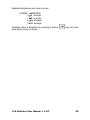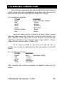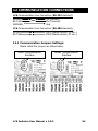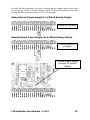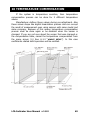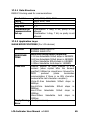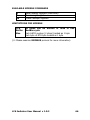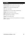
1
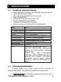
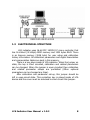
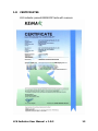
17/09/2004
LCA Indicator User Manual v 1.0.2
2
CONTENTS
CONTENTS...............................................................................3
OVERVIEW ..............................................................................5
1
SPECIFICATIONS.............................................................6
1.1
1.2
1.3
1.4
1.5
1.6
1.7
1.8
2
SCREEN APPEARANCE ...................................................13
2.1
2.2
3
TECHNICAL SPECIFICATIONS........................................ 6
SYSTEM REQUIREMENTS .............................................. 6
ELECTRONICAL STRUCTURE ......................................... 8
OPERATING SPECIFICATIONS ....................................... 9
DISPLAY SPECIFICATIONS ............................................ 9
CONTROL SPECIFICATIONS (OPTION) ......................... 10
CERTIFICATES ........................................................... 12
PHYSICAL DIMENSIONS.............................................. 11
DISPLAY SYMBOLS ..................................................... 13
KEYS......................................................................... 14
ASSEMBLING AND POWER-UP ......................................15
3.1
3.2
3.3
3.4
3.5
3.6
3.7
3.8
3.9
START UP .................................................................... 16
INDICATOR VALUE RANGE ................................................ 16
ZERO PROCESS ............................................................. 16
AUTOMATIC ZERO .......................................................... 16
UNITS ........................................................................ 16
TARE (SEMI-AUTOMATIC TARE)......................................... 17
NUMERICAL TARE .......................................................... 17
DATE AND TIME ............................................................ 17
PROGRAM VERSION ........................................................ 17
4
SAFETY PRECAUTIONS ..................................................18
5
LCA INDICATOR WORKING DIAGRAM..........................19
5.1
PARAMETERS AND THEIR MEANINGS .................................... 21
5.1.1 #IDENTITY: .......................................................... 21
5.1.2 #DISPLAY SETUP: .................................................. 23
5.1.3 #CALIBRATION: .................................................... 27
5.1.4 #INPUT SETUP: ..................................................... 29
5.1.5 #OUTPUT SETUP: .................................................. 33
5.1.6 #COMM SETUP: ..................................................... 38
5.2
WEIGHT CALIBRATION............................................... 44
LCA Indicator User Manual v 1.0.2
3
5.2.1
5.2.2
5.2.3
6
PRE-ADJUSMENTS & GAIN SETUP ............................ 44
ZERO CALIBRATION ............................................... 46
LOAD CALIBRATION ............................................... 47
NORMAL WEIGHING .....................................................48
6.1
6.2
6.3
RESETTING SCREEN VALUE TO ZERO ................................... 48
ACTIVATING TARE .......................................................... 48
DISABLING TARE VALUE................................................... 49
7
ERROR MESSAGES.........................................................50
8
PROBLEMS AND SOLUTIONS.........................................51
9
POWER SUPPLY SPECIFICATIONS ................................52
10
OPERATING TEMPERATURE ......................................52
11
LOADCELL CONNECTION ...........................................53
12
COMMUNICATION CONNECTIONS ............................54
12.1
13
13.1
13.2
COMMUNICATION JUMPERS SETTINGS:................................. 54
OPTION......................................................................55
ANALOG OUTPUT OPTION .......................................... 55
RELAY OPTION .......................................................... 58
14
PC SOFTWARES .........................................................60
15
DIGITAL LINEARIZATION .........................................62
16
TEMPERATURE COMPENSATION ...............................63
17
COMMUNICATION STRUCTURE .................................64
17.1
PHYSICAL STRUCTURE ............................................... 64
17.2
LCA INDICATOR RS485 SPECIFICATIONS ............................. 64
17.2.1
DATA STRUCTURE .................................................. 65
17.2.2
APPLICATION LAYER ............................................... 65
18
TERMS........................................................................67
19
DRAWINGS ................................................................68
LCA Indicator User Manual v 1.0.2
4
OVERVIEW
LCA (Load Cell Amplifier) is a smart signal converter which is
designed for harsh industrial environments. The most distinctive
feature of LCA is, its ability to expose all of its parameters using the
MODBUS protocol.
Features:
• High internal resolution
• Digital filter
• Linearization
• Temperature compensation
• ModBus protocol
• Internal voltage supply circuitry is isolated from the external
voltage supply
• Isolated communication lines
• Temperature sensor
• LCD display
• 2 relay outputs
• 4-20mA Analog output module
• Eeprom memory for user Set-Up and Calibration information.
• 24-bits Resolution
• MODBUS protocol
• IP-66 protection class for industrial applications
LCA Indicator User Manual v 1.0.2
5
1 SPECIFICATIONS
1.1
TECHNICAL SPECIFICATIONS
•
•
•
•
•
•
•
•
Easily adjustable parameter and calibration menu by keypad
Up to 160 mV/V input range
Gain adjustment according to sensor output
Sense compensation
Works with 12-24 Volt supply (DC / AC)
Up to 8 Load cells are connectable
Industrial IP 66 protection class case
Remote control, parameter Set-Up and Calibration
Model
Input
A/D Speed (/second)
Display Resolution
Display
Maximum Range
Communication
Optional Futures
Load cell Excitation
Power Supply
Weighing Accuracy
EMC
1.2
LCA
DC voltage: -1,60 Volt to 1,60 Volt
50
1/100.000
LCD (2x16 character)
7 digit (-9999999 to +9999999)
RS-232C / RS-485 selectable
4-20mA analog output, 2 relay outputs
250mA (8 load cell) at 10 VDC
12-24 Volt DC / AC
10000d
EN 55011:2002 Emission - Class,
EN 45501:1992/AC:1993 Metrological
Aspects of Non-Automatic weighing
Instruments.
Passed
with
tests;
Electrostatic
Discharges (ESD), Radiated AM Field,
Electrical Fast Transient (EFT)/Burst
Transients, Power Supply Voltage
Variations, Dips and Interruptions by
KEMA
SYSTEM REQUIREMENTS
A power supply and a sensor (Load cell) are required for
standard connection. And additional modules for proper using;
•
JUNCTION BOX: If the system consists of more than one
LCA Indicator User Manual v 1.0.2
6
load cell, then a junction box is used for gathering the load cell
outputs to the LCA device.
• COMPUTER (PC): If a computer will be used for monitoring
the measured value as indicator (in LCA-X model) or both PC and
LCA device (in LCA-D model) will display the measured value, then a
computer with standard configuration will be required.
Minimum Configuration: P100MHz processor, 8Mb RAM, 500Mb
hard-disc and at least an RS232 port.
And also if there is a network system, a Network adapter is required
to work with the Network workgroup.
(NOTE: According to the selected PC Software, minimum
configuration can be changed. If there is only measurement transfer
to the PC or user operations (Tare, Zero etc.) from LCA devices with
PC program, minimum configuration and operation system is enough
to execute. Otherwise if there is a data record, computer should work
on power-on state continuously and automatically records the
weighing data. For this reason, the PC should have the qualifications
that can work with safety operating systems WinNT, Win2000 or
similar and enough hard-disc capability.)
• RS232/485 CONVERTER: If RS-485 communication base
will be used for communication an RS232/485 Converter must be
used between PC and device(s) to adapt device(s) and computer.
(NOTE: To communicate with more than one device at the same
bus, RS-485 Communication must be used. Furthermore, because of
long distance between devices and PC, RS-485 communication must
be used. For 0-50 meters RS-232, more than 50 meters RS-485
communication must be preferred)
LCA Indicator User Manual v 1.0.2
7
1.3
ELECTRONICAL STRUCTURE
LCA indicator uses 16-bit PIC 18C252 IC micro controller that
has 16 kWord (32 kByte) ROM memory and 1532 bytes RAM. There
is an Eeprom memory (2048 byte) for user setup and calibration
history information. All calibration parameters and digital linearization
and compensation tables are kept in this memory.
There is a key place inside of LCA indicator. When the jumper on
state, the key is short circuited, calibration and related parameters
can be changed. When the jumper is open circuited then calibration
and related parameter setups are prohibited (Other optional
parameters can be changed any time).
After calibration and parameter set-up, this jumper should be
left in open-circuit state. This protection key is placed inside of LCA
device and the cover must be unlocked to short-circuit this jumper.
LCA Indicator User Manual v 1.0.2
8
1.4
OPERATING SPECIFICATIONS
•
•
•
•
•
1.5
Following functions can be adjusted by keypad.
1. Accessing to the device identity information.
2. Screen parameters can be changed.
3. Calibration process can be done.
4. Digital filtering and communication parameters can
be adjusted.
5. Zero and Tare operations can be done.
No-motion detection.
Center of Zero detection.
Warning above maximum allowable value and other error
conditions (Related error message appears on the screen,
“ErrXX”).
All parameters and calibration process can be changed from
remote point.
DISPLAY SPECIFICATIONS
•
•
•
•
LCD screen shows the following data:
1. 7 digit measurement result
2. Net/Gross symbol
(N-0.000050kg)
3. Tare value
(T 1.000000 )
4. Relay state
(1, 2)
5. Level of scaling
( e1 / e2 )
6. No-motion state
(S)
7. Center-of-Zero
(Z)
Displaying measurement with decimal point (1.000000kg)
Wide view angle screen
LCD backlighting
LCA Indicator User Manual v 1.0.2
9
1.6
CONTROL SPECIFICATIONS (OPTION)
• 4-20 mA or 0-10V analog output (16 bits resolution)
This module supplies self-calibrated adjustable current output. It
can easily be configured for the required range. (
See, 5.1.5
#OUTPUT SETUP)
• Relay option
LCA indicator has two optional relay outputs. Relay contacts can
be adapted as NormallyClosed/NormallyOpen. (
See, 5.1.5
#OUTPUT SETUP)
• Digital Input
LCA indicator has two optically isolated digital inputs. This feature
is for proper using.
LCA Indicator User Manual v 1.0.2
10
1.7
PHYSICAL DIMENSIONS
Dimensions
Width
130 mm
Height
171 mm
Depth
50 mm
LCA-D
Dimensions
Width
130 mm
Height
171 mm
Depth
50 mm
LCA-X
LCA Indicator User Manual v 1.0.2
11
1.8
CERTIFICATES
LCA indicator passed KEMA EMC tests with success.
LCA Indicator User Manual v 1.0.2
12
2 SCREEN APPEARANCE
Level of scaling in MultiInterval or Multi-Range
(e1/e2)
GROSS value. Shows the
NET value with “N” symbol
when Tare is active.
Shows the unit of the
measurement.
(g, kg, lb, N, kN etc.)
Shows the Tare value with “T” symbol,
when Tare is active.
Shows the activated
relays.
No-Motion symbol.
(Stable)
Center-of-Zero symbol.
(Zero)
2.1
DISPLAY SYMBOLS
No-Motion
(S):
If there is
stability
on
platform, then ‘S’ symbol appears on the screen.
the
Center-of-Zero (Z):
If displayed value is zero and the internal
count is within ±1/4d, ‘Z’ symbol appears on the screen.
Relay1 State
(1):
Relay1 is activated.
This symbol appears on the screen when
Relay2 State
(2):
Relay2 is activated.
This symbol appears on the screen when
Net
(N):
Appears on the screen when Tare is active.
Notifies that displayed value is NET.
LCA Indicator User Manual v 1.0.2
13
Tare
(T):
Shows current Tare value.
Unit (g, kg, mV/V…): Shows the measurement unit in use. Can be
changed in set-up menu.
Scale Type
(e1):
Indicates that measured value is in first scale
interval range when Scale Type is Multi-Interval or Multi-Range. (Not
shown in Single-Interval mode)
Scale Type
(e2):
Indicates that measured value is in second
scale interval range when Scale Type is Multi-Interval or Multi-Range.
(Not shown in Single-Interval mode)
2.2
KEYS
Zero Key:
Makes screen value 0 (zero) if within
allowable limits.
Tare Key:
Sets current screen value as Tare value or
disables the previous Tare value. Works as toggle.
Function:
If this button is pressed for 3 seconds or
more, then Parameter Set-Up menu appears on the screen.
(
See. 5 LCA INDICATOR WORKING DIAGRAM)
LCA Indicator User Manual v 1.0.2
14
3 ASSEMBLING and POWER-UP
LCA Indicator has internal connection terminals. Relevant
connections are done with these terminals. There is an explanation
on the LCA board that represents the meaning of each terminal.
Beginning with left side to right side on the LCA board (1 to 22) each
terminal meaning is given below:
1.
2.
3.
4.
5.
6.
7.
8.
9.
10.
11.
12.
13.
14.
15.
16.
POWER+
POWER0
GROUND
RS Rx/A
RS Tx/B
RELAYC
RELAY1
RELAY2
INPUTC
INPUT1
INPUT2
ANALOG+
PULSEIN
4/20mA
ANALOGSHIELD
17.
18.
19.
20.
21.
22.
–S
–E
–I
+S
+E
+I
:
:
:
:
:
:
:
:
:
:
:
:
:
:
:
:
Power Supply (+ Pin for DC Supply)
Power Supply (– Pin for DC Supply)
Earth for device body.
Rx pin for RS-232, A pin for RS-485
Tx pin for RS-232, B pin for RS-485
Common pin for both Relays.
Contact connection for Relay1.
Contact connection for Relay2.
Common pin for digital inputs.
Digital input 1 (Opto isolated).
Digital input 2 (Opto isolated).
+ Power supply for 4-20 mA or Pulse Input.
+ Connection for 4-20 mA analog output.
4-20 mA analog output.
– Power supply for 4-20 mA or Pulse Input.
Load cell ground connection (Same point
with devices internal ground)
: -Sense
Load cell
: -Excitation
Load cell
: -Input
Load cell
: +Sense
Load cell
: +Excitation Load cell
: +Input
Load cell
It is enough to connect Power (1:Power+, 2:Power0) and Load
cell (17..22, -S, -E, -I, +S, +E and +I) connections to device
terminals for stand alone working as minimum requirements (
Section 1.2, MINIMUM REQUIREMENTS). When LCA device is first
energized “ROM VERSION NO” appears on the screen and tests
memory functions, then displays normal measurement screen.
LCA Indicator User Manual v 1.0.2
15
3.1
Start Up
When LCA is powered up, measured value appears on the
screen. This value comes from previously saved calibration and user
zero point values. Also if there is a linearization and/or temperature
compensation, screen value depends on these tables. Zero point
moves to last saved user zero value.
3.2
Indicator Value Range
The result of the measurement can be from “–Max.-9e” to
“Max.+9e” value (according to Gross value). If the screen value
exceeds over these values then related screen message is shown
(measured value will not be shown).
3.3
Zero Process
A new zero reference can be processed by pressing Zero key.
Also screen value equals to zero and Center of Zero symbol (‘Z’)
appears on the screen.
Allowable Zero Limits: %4 of maximum value (OIML IR76,
4.5.1)
Zero operation can only be set when screen value is GROSS. If
there is a tared value (Screen showing Net value) then Zero process
cannot be executed.
3.4
Automatic Zero
No permission to automatic zero.
3.5
Units
LCA indicator can be Set Up with different unit alternatives
for the measured unit. This units are “kg”, “lb”, “t”, “g”, “oz”, “N”,
“kN”, “mV/V”, “V” and “mb” (
See, 5.1.2 #DISPLAY SETUP). This
Set Up can be done by keypad or by MODBUS.
LCA Indicator User Manual v 1.0.2
16
3.6
Tare (Semi-Automatic Tare)
Current screen value (Gross) becomes Tare value when Tare
) key pressed. If tare is active, ‘N’ symbol appears on the
(
measurement screen, which indicates that the value on the screen is
NET value. Tare value appears on the second line with ’T’ symbol.
When Tare is active, if there is a stable condition with Net
value (bigger than 1), Tare value will be set to zero after a zero or
negative measurement (Gross) confirmed.
NOTE: If screen value is unstable (There is a motion condition, no ‘S’
symbol) or screen value is negative, and then tare process is
prohibited.
) key again cancels Tare value.
Pressing Tare (
Tare operation can be done by MODBUS, too.
3.7
Numerical Tare
LCA indicator does not support getting known tare values
from memory feature.
3.8
Date and Time
Production date, calibration date and number of calibrationprocessed information are kept in Eeprom memory. While during
calibration process, calibrating PC program automatically saves the
new calibration date to the memory. There is no Real Time Clock
module inside of LCA devices.
3.9
Program Version
Program revision number appears on the screen when start-up
occurs.
LCA Indicator User Manual v 1.0.2
17
4 SAFETY PRECAUTIONS
•
•
•
After all connections are completed, power-up the device. Do
not modify the current connections while device is powered
up and working.
Please operate with the notified temperature ranges.
Always use the power supply given together with the
indicator or a similar one with specifications.
LCA Indicator User Manual v 1.0.2
18
5 LCA INDICATOR WORKING DIAGRAM
) key is pressed for 3 seconds or more, then
If Function (
menu screen appears. There are six headline menus and they are as
follows:
•
•
•
•
•
•
#IDENTITY
#DISPLAY SETUP
#CALIBRATION
#INPUT SETUP
#OUTPUT SETUP
#COMM SETUP
Meaning of the keys (Exit Menu Enter) appears on the
second line of screen when one of these headlines are listed. Menu
screen looks like as follows:
#IDENTITY
Exit Menu Entr
According to this logic, each key meaning is stated below.
Exit:
The Zero key is used. When this key is pressed,
menu screen goes off and returns to normal measurement screen.
Menu:
The Tare key is used. Menu screen switches to next
headline of menu when this button is pressed. (#IDENTITY, #DISPLAY
SETUP, #CALIBRATION, #INPUT SETUP, #OUTPUT SETUP, COMM SETUP)
Enter:
The Function key is used. When this key is pressed
on the menu screen, related parameter setup screen is displayed.
One of these headlines can be selected by pressing Function
) key. Meaning of the parameter and parameter number that is
(
to be modified or read from the screen, appears on the LCD’s upper
line. The parameter’s alternatives or parameter value will be
LCA Indicator User Manual v 1.0.2
19
displayed on the second line of LCD. Related parameter digit blinks
and helps us which digit is about to be changed.
EXAMPLE:
If parameter 16 (P16) “#INPUT SETUP”, “P16:Input
) key
Range” is wanted to be changed, then, first Function (
must be pressed for 3 seconds or more to enter the menu screen.
Later, menu screen appears on the LCD as below:
#IDENTITY
Exit Menu Entr
Pressing Tare (
) key on this menu screen causes switching the
other headlines. Switch to the #INPUT SETUP headline by pressing
) key. Screen appearance will be as follows when this
Tare (
headline appeared on the screen:
#INPUT SETUP
Exit Menu Entr
After then, enter to the parameter entry screen by pressing Function
(
) key. LCD appearance will be as below:
P16:Input Range
1 2.50 mV/V
The alternatives from 0 to 7 can be switched by pressing Zero (
)
key. Changeable parameter alternative blinks and the meaning of the
alternative is seen next to the number. When Function (
) key is
pressed, selected parameter value is saved and parameter screen
switches to the next parameter screen. The alternatives that belong
to this parameter are:
ALTERN
MEANING
0
1,25 mV/V
1
2,50 mV/V
2
5,00 mV/V
LCA Indicator User Manual v 1.0.2
20
3
4
5
6
7
5.1
5.1.1
10,0
20,0
40,0
80,0
160
mV/V
mV/V
mV/V
mV/V
mV/V
Parameters and Their Meanings
#IDENTITY:
This headline contains some identity information about the
device. These parameters are previously generated values in the
factory and each of these parameters cannot be change by keypad or
ModBus. The topics included in this headline are; serial number, ROM
version, number of calibration times, PC software version that used
for calibration process and calibration date information. These are:
P00:Serial Num:
Shows the device’s serial number.
Screen appearance will be as follows:
P00:Serial Num
0000012
─
Since this is an unchangeable value, cursor blinks on the right bottom
of the LCD.
Passing to the next parameter screen is by pressing Function (
key.
)
P01:ROM VERSION: Shows micro-controller’s software
version. Screen appearance will be as follows:
P01:Rom Version
0000010
─
Passing to the next parameter screen is by pressing Function (
)
key.
P02:CustomerCode: Specific number for customers. Screen
appearance will be as follows:
P02:CustomerCode
0000001
─
LCA Indicator User Manual v 1.0.2
21
Passing to the next parameter screen is by pressing Function (
key.
)
P03:Calibr.Times: This information shows number of
calibration done. (Automatically incremented when calibration is
done). Screen appearance will be as follows:
P03:Calibr.Times
0000065
─
Passing to the next parameter screen is by pressing Function (
key.
)
P04:PC Cal. Soft.: Personal code or PC software version
number that the calibration process was made by. (The calibrating PC
program automatically writes its own code to this area. If calibration
is made by keypad, this value automatically sets itself to 0 [zero]).
Screen appearance will be as follows:
P04:PC Cal. Soft
00
─
Passing to the next parameter screen is by pressing Function (
key.
)
P05:Calibr.Date: Calibration date information. The PC
software that calibration made by, writes the calibration date to this
area. If calibration process is made by keypad then this value will be
displayed as “----“ (unchangeable value). Screen appearance will be
as follows:
P05:Calibr. Date
––––
─
Passing to the next parameter screen is by pressing Function (
)
key. (This is the last parameter screen. So, device returns to the
headline screen)
LCA Indicator User Manual v 1.0.2
22
5.1.2
#DISPLAY SETUP:
This headline contains parameters about decimal point
position, measurement unit, scale type, Max, Max1, Max2 and step
(e1/e2) values.
P06:Decimal Pt: Decimal point position adjustment.
Maximum display value is 7 digit (9999999). According to this,
alternatives are from 0 to 6.
ALTERN MEANING
0 9999999 (no decimal point)
1 999999.9 (decimal point on 1st digit)
.. ..
(………)
6 9.999999 (decimal point on 6th digit)
(NOTE: Alternatives above 7 will not be displayed)
Screen appearance will be as follows:
P06:Decimal Pt
2
The digit, that is about to be changed, blinks for indicating the
changeable value. The number on the flashing digit increases by
pressing Zero (
Function (
) key. Selected value is accepted by pressing
) key and next parameter screen is shown.
P07:Unit Set: Measurement unit (g, kg, br, mV/V) for
measured quantity. Alternatives from 0 to 9 and their meanings will
be shown on the LCD screen. Screen appearance will be as follows:
P07:Unit Set
2 kg
The new set value is blinks and meaning of the parameter is shown
next to this value. The number on the flashing digit is increased by
) key. Alternatives and meanings are like as:
pressing Zero (
ALTERN MEANING
0g
1 kg
2t
3 oz
LCA Indicator User Manual v 1.0.2
23
4 lb
5N
6 kN
7 mV/V
8V
9 (no unit)
Selected value is accepted by pressing Function (
parameter screen is shown.
) key and next
P08:Scale Type: Scale Type for the measurement is
determined in this parameter by choosing one of the alternatives
from Single-Interval, Multi-Interval or Multi-Range. If there are two
different steps for the measurement, selection must be Multi-Interval
or Multi-Range. Screen appearance will be as follows:
P08:Scale Type
0 Single
The new set value blinks and meaning of the parameter shown next
to this value. The number on the flashing digit is increased by
) key. Related alternatives and means are like as:
pressing Zero (
ALTERN MEANING
0 Single
1 Mult Int
2 Mult Rng
As can be understood from the figure in above, when one of
multi modes are used, measurement area can be evaluated as two
LCA Indicator User Manual v 1.0.2
24
different areas. According to this, passing value from 1st area to 2nd
area is at “Max1+9e1”. As known in Single Mode, when the maximum
(“Max+9e”) value exceeds then “Maximum” error message is
displayed. In Multi modes, two different areas are separated with
their own “Max” and “e” (Max1, e1 and Max2, e2) values. In MultiInterval mode, e1 step value is valid from 0 (zero) to ‘Max1+9e1’ and
from ‘Max1+9e1 to ‘Max2+9e2’ e2 step is valid. In Multi-Range
mode: e1 step value is valid from 0 (zero) to ‘Max1+9e1’ and e2 step
is valid from ‘Max1+9e1 to ‘Max2+9e2’ too. But, there is no return
from e2 to e1 on the ‘Max1+9e1’ value. Passing e2 step to e1 occurs
when the screen value is Zero or negative (Absolute Zero).
NOTE: If one of multi modes is chosen, Max1 and e1 alternatives
are shown in the following parameter set up screens, too. If SingleInterval is chosen, then only Max (maximum value) and e (step)
values are shown on the parameter Set-up menu.
Selected value is accepted by pressing Function (
parameter screen is shown.
) key and next
P09:(e1) Step: This step value is valid from 0 to
“Max1+9e1” screen value (first-interval area) in Multi-Interval or
Multi-Range selected measurements. Screen value increases or
decreases with this step value. It can be 1, 2, 5, 10, 20 or 50.
If Single-Interval scale type is selected then this parameter
screen message looks like “P09:(e ) Step” or if Multi-Interval or MultiRange is selected then the screen message looks like “P09:(e1) Step”.
Screen appearance will be as follows:
P09:(e1) Step
0 1
The new set value blinks and meaning of the parameter is shown
next to this value. The number on the flashing digit is increased by
) key. Related alternatives and means are like as:
pressing Zero (
ALTERN MEANING
0 1
1 2
2 5
3 10
4 20
LCA Indicator User Manual v 1.0.2
25
5 50
Selected value is accepted by pressing Function (
parameter screen is shown.
) key and next
P10:Max1 Value: When the measurement area is evaluated
as two different areas (Multi-Range or Multi-Interval), there is a
transition value (Max1) from e1-paced area to e2-paced area. (This
parameter setup menu will not shown in Single-Interval mode)
Screen appearance will be as follows:
P10:Max1 Value
00150.00
kg
The new set value that is about to be changed blinks. The
number on the flashing digit is increased by pressing Zero (
) key.
) key, flashing digit moves to the next digit.
By pressing Tare (
Measurement unit will be displayed on the right corner of LCD.
Selected value is accepted by pressing Function (
parameter screen is shown.
) key and next
P11:(e2) Step: Step value for Multi-Range and MultiInterval modes in second interval area (1, 2, 5, 10, 20 or 50). (If
Single-Interval mode is selected then this parameter setup menu will
not be displayed). Screen appearance will be as follows:
P11:(e2) Step
2 5
The new set value blinks and meaning of the parameter is
shown next to this value. The number on the flashing digit is
increased by pressing Zero (
) key.
Selected value is accepted by pressing Function (
parameter screen is shown.
) key and next
P12:Max2 Value: Maximum value. This is the maximum
screen value that can be displayed for the measurement. If one of
LCA Indicator User Manual v 1.0.2
26
Multi modes are chosen then screen appearance will look like
“P12:Max2 Value”, otherwise the screen appearance will look like
“P12:Max Value”. Screen appearance will be as follows:
P12:Max2 Value
00500.00
kg
The new set value that is about to be changed blinks. The
number on the flashing digit can be increased by pressing Zero (
)
) key, flashing digit moves to the next
key. By pressing Tare (
digit. Measurement unit will be displayed on the right corner of LCD.
Selected value is accepted by pressing Function (
parameter screen is shown.
5.1.3
) key and next
#CALIBRATION:
In this menu calibration process is done. Also this screen can
be used for monitoring internal counts. If you do not want to change
anything then choose ‘No’ alternative, otherwise calibration can be
modified or corrupted.
P13:Set ZERO?: In this section calibration zero is saved to
the device non-volatile memory. On this parameter, screen
appearance looks like as follows;
P13:Set ZERO?
Yes
1476
In this setup screen, “Yes” or “No” alternatives can be
) key. Internal counts appear on the
selected by pressing Zero (
right bottom of LCD. Calibration Zero can be set by pressing
) key while “Yes” alternative is active on the screen.
Function (
There will be no changes to Calibration Zero if “No” alternative on
the screen.
P14:Set LOAD?: In this screen, calibrating value is
determined. Screen appearance looks like as follows:
LCA Indicator User Manual v 1.0.2
27
P14:Set LOAD?
Yes
132476
“Yes” or “No” alternatives can be selected by pressing Zero (
)
key. Internal counts appear on the right bottom of LCD. If Function
) key is pressed while “Yes” alternative is active on the screen
(
the secondary calibration screen is displayed for calibration process.
There is no change to the Calibration area if “No” alternative was
selected
(NOTE: If this parameter screen is passed with “No” selection,
“P15:SCALE VALUE” menu will not be shown)
P15:SCALE VALUE: Determines the value that to is to be
scaled as the reference value. Screen appearance will be as follows:
P15:SCALE VALUE
00100.00
kg
The new set value that is about to be changed blinks. The
number on the flashing digit can be increased by pressing Zero (
)
) key, flashing digit moves to the next
key. By pressing Tare (
digit. Measurement unit appears on the right corner of LCD.
On this screen, the value that is to be scaled is given for current
internal counts. This is the value for the reference known value that
the calibration is done.
Selected value is accepted by pressing Function (
Calibration process is completed.
) key.
EXAMPLE:
After the calibration Zero is set, if there is a value like as
above (‘132476’) on the screen, choosing “Yes” alternative and then
) key, brings “P15:SCALE VALUE” to the
pressing Function (
screen. On this screen, setting “10000” as scaling value, means that
calibrate this internal count (132476) to 10000 screen value.
LCA Indicator User Manual v 1.0.2
28
5.1.4
#INPUT SETUP:
This menu item contains digital filtering, input range (mV/V)
and temperature parameters.
P16:Input Range: Determines input range (1,25 - 2,50 ..160mV/V). Appropriate analogue input signal is chosen according to
the sensor type. Screen appearance will be as follows:
P16:Input Range
01.25
mV
The new set value blinks and meaning of the parameter is shown
next to this value. The number on the flashing digit is increased by
) key. Related alternatives and means are as:
pressing Zero (
ALTERN MEANING
0 1,25 mV/V
1 2,50 mV/V
2 5,00 mV/V
3 10,0 mV/V
4 20,0 mV/V
5 40,0 mV/V
6 80,0 mV/V
7 160 mV/V
Selected value is accepted by pressing Function (
parameter screen is shown.
) key and next
P17:Filter Size: Amount of measurement for arithmetical
average calculation (0..3).
Each A/D conversion result is kept in buffer memory for average
calculation. According to this, amount of measurement can be
changed by this parameter. Screen appearance will be as follows:
P17:Filter Size
3
The new set value flashes and meaning of the parameter is
shown next to this value. The number on the flashing digit is
) key.
increased by pressing Zero (
(Buffer Size = 4x2^n, n: alternative)
LCA Indicator User Manual v 1.0.2
29
Related alternatives and means are as:
ALTERN MEANING
0 4 average
1 8 average
2 16 average
3 32 average
Selected value is accepted by pressing Function (
parameter screen is shown.
LCA Indicator User Manual v 1.0.2
) key and next
30
P18:Flt.Toleranc: Amount of unstable internal counts for
digital filtering can be determined with this parameter (0..9).
Variations on internal counts can be compensated with this
parameter. This parameter determines the permitted amount of
internal counts between one after another measurement. The new
measured value will be ignored when internal count value exceeds
previous value by this tolerance value. (Number of rejected
measurements can be determined in “P19:Escape Count”)
Screen appearance will be as follows:
P18:Flt.Toleranc
5
The new set value blinks and the number on the flashing
) key.
digit is increased by pressing Zero (
( 8x2^n, n: Selected value)
Related alternatives and means are like as:
ALTERN MEANING
0
8 count
1
16 count
2
32 count
3
64 count
4
128 count
5
256 count
6
512 count
7
1024 count
8
2048 count
9
4096 count
Selected value is accepted by pressing Function (
parameter screen is shown.
) key and next
P19:Escape Count: Number of measurements that is to be
ignored when the measured value is over than the limit in parameter
(“P18:Flt.Toleranc”). According to this value (0-.99), if following
measurements exceeds the limit value then adapting to the new
value is facilitated. This means, new screen value exists after this.
This condition can be explained like as:
There is a system with maximum 100kg capacity. Changing
on the platform with 5kg weight will cause soft transition to the new
value or fast response at once to the new value? If fast response
LCA Indicator User Manual v 1.0.2
31
required than P18 and P19 parameters must be set to smaller
values. In this way, new value is ignored for a little time than
buffered old values are cleared and adapted to the new value.
Otherwise new measured values are kept on adding in the average
buffer. In this way adapting to the new value is slower. Screen
appearance will be as follows:
P19:Escape Count
05
The new set value that is about to be changed blinks. The
number on the flashing digit is increased by pressing Zero (
) key.
) key, flashing digit moves to the next digit.
By pressing Tare (
Selected value is accepted by pressing Function (
parameter screen is shown.
) key and next
P33: Temp.Compens: This parameter determines whether
the temperature compensation is ON or OFF (Yes/No). Temperature
sensor can be activated by choosing the ‘Yes’ alternative. In this way
current temperature value appears on the right corner of LCD. This
parameter especially determines temperature compensation is
operating on state or not. This means that digital compensation is
on!!! Temperature compensation is a specific application for sensors
and each sensor has its own multiplier constant values that is found
during manufacturing. If current sensor is changed with a new one
then the values used previously become invalid. Be careful about the
tables that temperature compensation uses. If you are not sure about
your compensation table values, choose ‘No’ alternative. Screen
appearance will be as follows:
P33:Temp.Compens
Yes
39˚C
In this setup screen, “Yes” or “No” alternative can be determined by
pressing Zero (
Function (
) key. Selected value is accepted by pressing
) key and next parameter screen is shown.
LCA Indicator User Manual v 1.0.2
32
5.1.5
#OUTPUT SETUP:
This menu contains information about relay setting and 4-20
mA analog output setup.
P20:SP1 NET/GRS: Set point 1 NET or GROSS. This
parameter determines the value that used with Relay1 is NET value
or GROSS value. If NET alternative is chosen then Relay1 is activated
with respect to the NET value. Screen appearance will be as follows:
P20:SP1 NET/GRS
0 NET
In this setup screen, alternatives can be changed by pressing Zero
(
) key. Related alternatives and means are as:
ALTERN MEANING
0 NET (Net value)
1 GRS (Gross value)
Selected value is accepted by pressing Function (
parameter screen is shown.
) key and next
P21:SP1 Value: Set Point for Relay1 (7 digit). Screen
appearance will be as follows:
P21:SP1 Value
00050.00
kg
The new set value that is about to be changed blinks. The
number on the flashing digit is increased by pressing Zero (
) key.
) key, flashing digit moves to the next digit.
By pressing Tare (
Measurement unit will be displayed on the right corner of LCD.
Selected value is accepted by pressing Function (
parameter screen is shown.
) key and next
P22:SP1 Abv/Belw: Activation condition for Relay1 is
determined in this parameter screen. Relay1 can energize above the
value that stated in “P21:SP1 Value” or below. Screen appearance will
be as follows:
LCA Indicator User Manual v 1.0.2
33
P22:SP1 Abv/Belw
0 Above
Transition between alternatives can be done by pressing Zero (
key. Related alternatives and means are like as:
ALTERN MEANING
0 Above
(Above the Set value)
1 Below
(Below the Set value)
Selected value is accepted by pressing Function (
parameter screen is shown.
)
) key and next
P23:SP2 NET/GRS: Set point 2 NET or GROSS. This
parameter determines the value that used with Relay2 is NET value
or GROSS value. If NET alternative chosen then Relay2 is energized
with NET value. Screen appearance will be as follows:
P23:SP2 NET/GRS
0 NET
In this setup screen, alternatives can be changed by pressing Zero
(
) key. Related alternatives and means are like as:
ALTERN MEANING
0 NET (Net value)
1 GRS (Gross value)
Selected value is accepted by pressing Function (
parameter screen is shown.
) key and next
P24:SP2 Value: Set Point for Relay1 (7 digit). Screen
appearance will be as follows:
P24:SP2 Value
00250.00
kg
The new set value that is about to be changed blinks. The
number on the flashing digit is increased by pressing Zero (
) key.
) key, flashing digit moves to the next digit.
By pressing Tare (
Measurement unit will be displayed on the right corner of LCD.
LCA Indicator User Manual v 1.0.2
34
Selected value is accepted by pressing Function (
parameter screen is shown.
) key and next
P25:SP2 Abv/Belw : Activation condition for Relay2 is
determined in this parameter screen. Relay2 can energize above the
value that stated in “P24:SP2 Value” or below. Screen appearance will
be as follows:
P25:SP2 Abv/Belw
0 Above
Transition between alternatives can be done by pressing Zero (
key. Related alternatives and means are like as:
ALTERN MEANING
0 Above
(Above the Set value)
1 Below
(Below the Set value)
Selected value is accepted by pressing Function (
parameter screen is shown.
)
) key and next
P26:SP Delay: 100ms sensitive delay for Relays. Up to 25.5
second can be determined with this parameter (00.0-25.5 sc). Screen
appearance will be as follows:
P26:SP Delay
00.5
sc
The new set value that is about to be changed blinks. The number on
the flashing digit is increased by pressing Zero (
) key. By pressing
) key, flashing digit moves to the next digit. Unit of value
Tare (
will be displayed on the right corner of LCD.
Selected value is accepted by pressing Function (
parameter screen is shown.
) key and next
P27:AN Net/Gross : Analog output (4-20 mA) can work
according to GROSS or NET value. Screen appearance will be as
follows:
LCA Indicator User Manual v 1.0.2
35
P27:AN NET/GRS
0 NET
Alternatives can be changed by pressing Zero (
alternatives and means are like as:
ALTERN MEANING
0 NET (Net value)
1 GRS (Gross value)
) key. Related
Selected value is accepted by pressing Function (
parameter screen is shown.
) key and next
P28:Analog From: Determines the analog outputs starting
point (00,000...31,999 mA). When screen value is Zero (Net or Gross
value, according to the selected value in “P27:AN Net/Gross”) then
analog output value will be as stated in this parameter. Screen
appearance will be as follows:
P28:Analog From
20.000
mA
The new set value that is about to be changed blinks. The number on
the flashing digit is increased by pressing Zero (
) key. By pressing
) key, flashing digit moves to the next digit. Unit of value
Tare (
will be displayed on the right corner of LCD.
Selected value is accepted by pressing Function (
parameter screen is shown.
) key and next
(This value (Analog From) is output when measured value is Zero (0)
and must be less than “Analog To” value (Output when screen value
is “Analog Maximum” that stated in parameter P30:Analog Max)
P29:Analog To..: Determines the analog output end point
(00,000...31,999 mA). When screen value is equal or greater than
Analog Maximum value (P30:Analog Max) (Net or Gross value,
according to the selected value in “P27:AN Net/Gross”) then analog
output value will be as stated in this parameter. Screen appearance
will be as follows:
LCA Indicator User Manual v 1.0.2
36
P29:Analog To..
04.000
mA
The new set value that is about to be changed blinks. The number on
the flashing digit is increased by pressing Zero (
) key. By pressing
) key, flashing digit moves to the next digit. Unit of value
Tare (
will be displayed on the right corner of LCD.
Selected value is accepted by pressing Function (
parameter screen is shown.
Attention:
These values can be set as:
0
4
Analog Max
20
or,
0
20
Analog Max
4
) key and next
mA (Analog From)
mA (Analog To)
mA (Analog From)
mA (Analog To)
P30:Analog Max: Maximum value for analog output. When
screen value is equal or greater than “Analog Max” (Net or Gross
value, according to the selected value in “P27:AN Net/Gross”) analog
output value will be as stated in “P29:Analog To..”. Screen appearance
will be as follows:
P30:Analog Max
010.000
kg
The new set value that is about to be changed blinks. The
number on the flashing digit is increased by pressing Zero (
) key.
) key, flashing digit moves to the next digit.
By pressing Tare (
Measurement unit will be displayed on the right corner of LCD.
Selected value is accepted by pressing Function (
parameter screen is shown.
LCA Indicator User Manual v 1.0.2
) key and next
37
5.1.6
#COMM SETUP:
In this menu communication parameters can be set (ModBus
ID, Protocol, baud rate, bits, parity, stop bits, response delay,
timeout delay).
P34:Modbus ID Nr: This value determines the device’s
communication address on the communication line (Bus ID number).
Can be set from 1 to 254.
Attention: Number 0 and 255 are used for special
applications.
ModBus ID=0
Continuous Mode
ModBus ID=255
Future Applications
Screen appearance will be as follows:
P34:Modbus ID Nr
000
If ID Number is set as 0, then signed (+,-) measured value is
tranferred via the serial port continuously. Transmitting format is
Ascii and finally “CR” (character 13) character is sent.
For example transmitting the measured value as “1204kg” is
transmitted like as:
‘+’(43), ‘0’(48), ‘0’(48), ‘0’(48), ‘1’(49), ‘2’(50), ‘0’(48), ‘4’(52),
chr(13 )
P34:Modbus ID
255
If ID Number=255 then communication parameters are
forced to work with known parameters 1200,n,8b,1s in RTU
protocol.
The new set value that is about to be changed blinks. The number on
the flashing digit is increased by pressing Zero (
) key. By pressing
) key, flashing digit moves to the next digit. Unit of value
Tare (
will be displayed on the right corner of LCD.
Selected value is accepted by pressing Function (
parameter screen is shown.
LCA Indicator User Manual v 1.0.2
) key and next
38
P35:CommProtocol: Protocol selection for Modbus
communication mode.
(NOT: If Modbus ID Number was selected as 0 (continuous mode)
then this parameter screen is not shown.)
Screen appearance will be as follows:
P35:CommProtocol
0R
Alternatives can be changed by pressing Zero (
alternatives and means are as:
ALTERN MEANING
0R
(RTU mode)
1A
(ASCII mode)
) key. Related
In shortly, according to MODBUS protocol: there are two ASCII
character represents to a byte in ASCII mode. For example character
0hAF in hex denoted, is transmitted as ‘A’ and ‘F’ characters and their
start-stop characters in ASCII mode. In RTU mode, each byte is
treated as one byte. For example character 0hAF is transmitted as
0xAF (decimal 175) and there are no start or stop characters in RTU
mode. Determining start and stop conditions for MODBUS frames,
timing between one data after another is checked.
(examine MODBUS protocol for RTU and ASCII concepts.)
Selected value is accepted by pressing Function (
parameter screen is shown.
) key and next
P36:Baudrate:
Communication
speed
selection
(1200..9600). It is recommended to use lower speeds for long
distances and noisy interfaces.
Screen appearance will be as follows:
P36:Baudrate
0 1200
Alternatives can be changed by pressing Zero (
alternatives and means are:
LCA Indicator User Manual v 1.0.2
) key. Related
39
ALTERN MEANING
0 1200
1 2400
2 4800
3 9600
Selected value is accepted by pressing Function (
parameter screen is shown.
) key and next
P37:Comm. Bits: Number of bits that to be used in
communication (7bit/8bit).
Screen appearance will be as follows:
P37:Comm. Bits
1 8b
Alternatives can be changed by pressing Zero (
alternatives and means are like as:
) key. Related
ALTERN MEANING
0 7b
1 8b
Selected value is accepted by pressing Function (
parameter screen is shown.
) key and next
P38:Comm. Parity: Communication parity bit selection
(none, even, odd parity)
Screen appearance will be as follows:
P38:Comm.Parity
0 n
Alternatives can be changed by pressing Zero (
alternatives and means are as:
ALTERN MEANING
0n
(no parity)
1o
(odd parity)
2e
(even parity)
LCA Indicator User Manual v 1.0.2
) key. Related
40
Selected value is accepted by pressing Function (
parameter screen is shown.
) key and next
P39:Comm. Stop: Communication stop bit selection (1stop,
2stop).
Screen appearance will be as follows:
P39:Comm. Stop
0 1s
Alternatives can be changed by pressing Zero (
alternatives and means are as:
ALTERN MEANING
0 1s
(1 stop)
1 2s
(2 stop)
) key. Related
Selected value is accepted by pressing Function (
parameter screen is shown.
) key and next
P40:Resp. Delay: Response delay.
Screen appearance will be as follows:
P40:Resp. Delay
008
ms
The new set value that is about to be changed blinks. The number on
the flashing digit is increased by pressing Zero (
) key. By pressing
) key, flashing digit moves to the next digit. Unit of value
Tare (
will be displayed on the right corner of LCD.
The values that are available in the parameter are:
0..255ms in 1200 baud (max 255ms),
0..127ms in 2400 baud (max 127ms),
0.. 63ms in 4800 baud (max 63ms),
0.. 31ms in 9600 baud (max 31ms).
If the value that is to be adjusted for this parameter is over than
maximum value than screen appearance will be as follows:
LCA Indicator User Manual v 1.0.2
41
Err:Resp. Delay
008
ms
In this case the value that entered must be changed with a valid
value.
Selected value is accepted by pressing Function (
parameter screen is shown.
) key and next
P41:TimeOut Dly.: Timeout delay. When there is an error
in communication, device waits for time out delay to end and then
prepares communication to ready state. Screen appearance will be as
follows:
P41:TimeOut Dly.
008
ms
The new set value that is about to be changed blinks. The number on
the flashing digit is increased by pressing Zero (
) key. By pressing
) key, flashing digit moves to the next digit. Unit of value
Tare (
will be displayed on the right corner of LCD.
The values that available in parameter are:
12..255ms in 1200 baud (max 255ms),
6...127ms in 1200 baud (max 127ms),
3.....63ms in 1200 baud (max 63ms),
2.....31ms in 1200 baud (max 31ms)
If the value that to be adjusted for this parameter is over than
maximum value than screen appearance will be as follows:
Err:TimeOut Dly.
008
ms
In this case the value that entered must be changed with a valid
value.
Selected value is accepted by pressing Function (
parameter screen is shown.
LCA Indicator User Manual v 1.0.2
) key and next
42
LCA Indicator User Manual v 1.0.2
43
|
P40:Resp. Delay
|
P41:TimeOut. Dly.
|
P26:SP Delay
|
P27:AN Net/Gross
|
P28:Analog From
|
P29:Analog To..
P30:Analog Max
|
P12:Max2 Value
|
P39:Comm. Stop
|
P36:Baudrate
|
P37:Comm. Bits
|
P38:Comm. Parity
|
P35:CommProtocol
|
P25:SP2 Abv/Belw
|
P21:SP1 Value
|
P22:SP1 Abv/Belw
|
P23:SP2 NET/GRS
|
P24:SP2 Value
|
P11:(e2) Step
|
P18:Flt.Toleranc
|
P19:Escape Count
|
P33:Temp.Compens
|
P17:Filter Size
|
P05:Calibr.Date
P15:Scale Value
|
P14:Set LOAD?
|
P08:Scale Tpe
|
P09:(e1) Step
|
P10:Max1 Value
|
P34:Modbus ID Nr
|
P02:Customer Code
|
P03:Calibr. Times
|
P04:PC Cal.. Soft
|
P20:SP1 NET/GRS
#COMM SETUP
|
P07:Unit Set
|
P16:Input Range
#OUTPUT SETUP
|
P01:Rom Version
|
P13:Set ZERO?
|
#INPUT SETUP
P06:Decimal Pt
#CALIBRATION
#DISPLAY SETUP
P00:Serial Num
|
#IDENTITY
5.2
WEIGHT CALIBRATION
Follow the topics arranged below for performing calibration
process correctly:
• After all connections have been done, the indicator should be
kept in power for at least 10 minutes before starting
calibration process.
• If possible, during this wait time, load and unload the weight
for a few times.
• Keep away all obstacles that may prevent load to be sensed
by the platform.
• The reference weight should better be approved by.
authorities.
• The calibration weight should better be at least half of the
capacity.
5.2.1
PRE-ADJUSMENTS & GAIN SETUP
Please contact authorized
Esit service personnel for
detailed
calibration
procedure
LCA Indicator User Manual v 1.0.2
44
Please contact authorized
Esit service personnel for
detailed
calibration
procedure
LCA Indicator User Manual v 1.0.2
45
5.2.2
ZERO CALIBRATION
Please contact authorized
Esit service personnel for
detailed
calibration
procedure
LCA Indicator User Manual v 1.0.2
46
5.2.3
LOAD CALIBRATION
Please contact authorized
Esit service personnel for
detailed
calibration
procedure
LCA Indicator User Manual v 1.0.2
47
6 NORMAL WEIGHING
To return to the normal measurement screen, press Zero (
) key
when menu screen is active. In the menu screen, each key’s meaning
explained under the upper side of keys. Therefore “Exit” operation is
) key. LCA device’s ROM version number
represented with Zero (
is shown on LCD screen for a while and then starts to operate with
normal measurement mode when LCA is powered up.
6.1
Resetting Screen Value to Zero
To reset screen value to zero, Zero (
) key is pressed. In
order to perform this function, the indicator should be in no-motion
(stable) state which can be realized with the “S” symbol on the LCD.
And also Tare is not active. Permission for zeroing screen value is
limited with %4 of Maximum capacity. Otherwise an error message
appears on the screen (See. Error Messages, ERROR-3,ZERO
LIMIT).
After the zero has been set, the Center-of-Zero point sign
(“Z”) appears on the left side of LCD.
6.2
Activating Tare
) key is pressed to make the screen value as Tare
Tare (
value. When there is an unstable condition (There is no “S” symbol
on the screen) this key is ignored. When Tare is activated, the display
value will be zero and tared value is shown on the second line of LCD
LCA Indicator User Manual v 1.0.2
48
with “T” symbol. Also “N” symbol appears on the front of screen
value. This means, measured value is Net value.
• In order to Tare a value, the screen value must be positive.
(There is no permission to Tare with negative value and if there is a
tared value then there is no zeroing operation)
• When Tare is active, Zero key is ignored.
6.3
Disabling Tare Value
) key again while Tare is active, will disable
Pressing Tare (
the Tare function. When tare is not active “T” symbol and tared value
on the second line of LCD goes off. The value on the screen is now
Gross value.
LCA Indicator User Manual v 1.0.2
49
7 ERROR MESSAGES
Because of wrong usage or some error conditions LCA device
displays the following messages:
ERROR-3
"ZERO LIMIT"
Cannot perform Zeroing. This value cannot be set to
) key. Because, there is a
zero by pressing Zero (
limitation for zeroing with maximum of %4. Can be
done with Zero Calibration.
ERROR-50
"CALIB.KEY!"
Calibration key is disabled. To perform this operation,
modification should be done on the LCA board.
ERROR-1
"MAXIMUM!!!"
Screen value is over. (Over than
Max:Maximum capacity, e: step value)
ERROR-22
"Eeprom Mem"
Non-volatile memory error. Please call service.
ERROR-90
"CONV.TOUT!"
ADC conversion is timed out. Chip not responding.
Please call service.
ERROR-5
"ADC RANGE!"
Internal counts are in over state. Check ADC gain
setup.
ERROR-91
"TEMP.TOUT!"
Time out for temperature sensor. Not responding.
Call service.
ERROR-99
"WATCHDOG! "
There is an unknown soft lock occurred and device
automatically RESET itself.
LCA Indicator User Manual v 1.0.2
Max+9e,
50
8 PROBLEMS and SOLUTIONS
☺
☺
☺
Nothing on screen and no backlight.
No energy is given to the device. The plug may be
loose or power is off. Check the voltages.
LCA can not communicate with electronic device
connected (PC,PLC..).
Check the communication parameters and cables.
The parameters must be same configured with the
electronic device that LCA is connected (Protocol,
baudrate, bits, parity, stop bits and Modbus ID
number must be same if works as Modbus Slave
device).
Check the cable and RS232/485 converter if used.
Weight can not be seen.
There can be a calibration error or wrong connection
in Load-cell cable. May need to perform calibration
again.
☺
Can not enter some menu topics.
Check whether calibration key jumper is linstalled.
☺
Keys not functioning.
Check whether any key is left pressed.
☺
Weight can not be reset to zero.
If the no-motion state is not achieved and ‘S’ symbol
is not the LCD screen then Zeroise operation can not
be performed. Increase the Digital Filtering values or
increase the step value. If zeroise operation can not
perform while ‘S’ (stable) symbol on the LCD screen
then Zero (
) key is broken. Call service.
LCA Indicator User Manual v 1.0.2
51
9 POWER SUPPLY SPECIFICATIONS
1
2
VOLT
12V
24V
POWER
5W
5W
Use one of the specified power
supplies for LCA indicator.
Isolation voltage minimum 2000 V.
10 Operating Temperature
Temperature Range: -10..50 °C
LCA Indicator User Manual v 1.0.2
52
11 LOADCELL CONNECTION
There are two power lines and two output lines on the Load cell
cables. Some load cells has additional sense lines. The colors on the
Esit Load cell cables and meanings are explained as follows:
For 6 wired load cell cable:
COLOR
Shield
Red
White
Black
Green
Orange (Yellow)
Blue
MEANING
Cover (Blendage, Shield)
- Output
+Output
- Excitation
+Excitation
- Sense
+Sense
Load cell cables can be 4 wired or 6 wired. When 4 wired
load cell cable used then there are no Sense Lines (Orange and
Blue). Because of this, these pins on LCA terminal must be shorted
with Power (Excitation) lines. [Jumper from +Sense (+S) to +Power
(+E) and from –Sense (-S) to –Power (-E)]
If the system consists of more than one load cell, then a
junction box is used for gathering the load cell outputs to the LCA
device.
For 4 wired load cell cable:
COLOR
MEANING
Shield
Cover
(Blendage, Shield)
Red
- Output
White
+Output
Black
- Excitation
Green
+Excitation
After checking the correct connection is supplied, power up the
device.
LCA Indicator User Manual v 1.0.2
53
12 COMMUNICATION CONNECTIONS
LCA Communication Line Connection (RS-232 standard);
RS Rx/A
Rx (Receive)
RS Tx/B
Tx (Transmit)
GROUND
Gnd
LCA Communication Line Connection (RS-485 standard);
RS Rx/A
RS A (Master device, PC etc..)
RS Tx/B
RS B (Master device, PC etc..)
12.1 Communication Jumpers Settings:
Please install the jumpers as stated below.
RS232 Communication
Interface
LCA Indicator User Manual v 1.0.2
RS485 Communication
Interface
54
13 OPTION
LCA device has a 4-20 mA analog output and two-relay outputs as
optional alternatives.
13.1 ANALOG OUTPUT OPTION
LCA indicator has a 4-20 mA analog output as option. D/A
module doesn’t need to be calibrated and offset adjusted. Analog
output range can be adjusted for the required output range and can
achieve 16 bit resolution.
Adjusting 4-20 mA Module:
At first, relational analog output parameter must be set correctly. For
doing this, selection for NET or GROSS value (P27), start point of
analog output (P28), end point for analog output (P29) and
maximum value for Analog output (P30)should be done. Setting
these parameters are shown below;
) key for 3 seconds or more, than
Pressing Function (
menu screen will appear on the LCD. Switch to the “#OUTPUT
SETUP” menu by pressing Tare (
(
) key and then press Function
) key to enter this menu item. Skip parameters from P20 to P26
by pressing Function (
) key.
P27:AN NET/GRS: This parameter determines the analog
output will reflect the Net or Gross value. Gross or Net alternative can
be changed by pressing Zero (
SETUP)
) key. (
See.
5.1.5 #OUTPUT
P28 :Analog From : When the screen value is Zero
(According to the selection on P27: NET/GRS), this value will be
output. This value can be set from 0.000 mA to 31.999 mA.
(
See. 5.1.5 #OUTPUT SETUP)
P29 :Analog To.. : When the screen value is Maximum
(P12 :Max Value), analog output will be as defined in this section.
(
See. 5.1.5 #OUTPUT SETUP)
LCA Indicator User Manual v 1.0.2
55
If an error or bigger value over than 31.999, entered values
will not be saved and an error message (“Err”) will appear on the left
corner of LCD. Screen appearance will be as follows:
Err:Analog From
32.000
mA
The entered value should be corrected with true value.
Example:
If the required analog output is,
15 mA for the “0“ screen value,
5 mA for the “Analog Max“ screen value
and analog output will reflect the Net value, than parameters should
be adjusted as follows;
(Analog Max value that can be found in P30 represents the Max
value for 4/20mA output)
P27:AN Gross/Net;
0 Nt
P28:Analog From;
15.000 mA
P29:Analog To..:
05.000 mA
NOT:
Analog output setup can be done as,
0
4 mA (Analog From)
Analog Max
20 mA (Analog To.. ),
And also can be done as,
0
20 mA (Analog From)
Analog Max
4 mA (Analog To.. )
Analog ouput module is optically isolated from the power of LCA
and Loadcell power lines. Principle of this module is based on adjustable
resistance on the lines. Because of this reason external power circuit should
LCA Indicator User Manual v 1.0.2
56
be used for this operation. And also, internal power supply unit can be used
for the power of the 4-20mA analog output. In this case isolation between
analog module and power lines of LCA is not meet.
Using internal Power Supply for 4/20mA Analog Output.
Install the jumpers
Using External Power Supply for 4/20mA Analog Output.
Do not install the
jumpers
Internal Power Supply
jumpers for Analog
Output
LCA Indicator User Manual v 1.0.2
57
13.2 RELAY OPTION
LCA indicator has two relay outputs that support 2A current at
220V. Each relay can be set with following method:
) key for 3 seconds or more, than
Pressing Function (
menu screen will appear on the LCD. Switch to the “#OUTPUT
SETUP” menu by pressing Tare (
(
) key and then press Function
) key to enter this menu headline.
P20:SP1 NET/GRS: Relational value for Relay1 output (Net
or Gross value)
(
See. 6.1.5 “#OUTPUT SETUP”)
(
P21:SP1 Value: Set point value for Relay1.
See. 6.1.5 “#OUTPUT SETUP”).
P22:SP1 Abv/Belw: Activating method for Relay1. Relay1
will activate above or below the set point value (defined in P21).
(
See. 6.1.5 “#OUTPUT SETUP”).
P23:SP2 NET/GRS: Operations on “P20:SP1 NET/GRS” are
done again for Relay2.
P24:SP2 Value: Operations on “P21:SP1 Value” are done
again for Relay2.
P25:SP2 Abv/Belw: Operations on “P22:SP1 Abv/Belw” are
done again for Relay2.
P26:SP Delay: Delay time for the relay outputs. Delay value
affects each relays in the same way with 100ms steps.
(
See. 6.1.5 “#OUTPUT SETUP”)
Example:
If the value on P26 is set as “01.0”, this means each relay will
be energized over the set point value and there will be a delay of
about 1 second.
LCA Indicator User Manual v 1.0.2
58
NOTE: After the Set Point value is exceeded and delay time has
finished then the relay will be energized, if the relay should be
deactivated, it is done so immediately.
LCA Indicator User Manual v 1.0.2
59
14 PC SOFTWARES
There exist 2 softwares for LCA indicator:
• Dlms_VP (Virtual Panel): Communicates with one LCA
device and can setup all user changeable parameters.
• Dlms_NW (NetWork): Communicates with more than one
device and can setup all user changeable parameters on each
device.
DLMS VP: (VIRTUAL PANEL)
DIGITAL LOADCELL MEASUREMENT SYSTEM VIRTUAL PANEL
This PC software is single user purposed. Measurement on LCA
device can be monitored and also all changeable parameters on the
device can accessed (scaling, calibration, communication format and
parameters, unit selection, optional setups etc.). Dlms_VP software
can communicate with only one LCA device. If there is an RS485 bus
then Dlms_VP can connect to each device on the bus separately.
This PC software can record the measured values in selected
periods. So, Dlms_VP can achieve automatical logging. (
Please
see DLMS_VP User Manual for detailed information)
LCA Indicator User Manual v 1.0.2
60
DLMS NW: (NETWORK)
DIGITAL LOADCELL MEASUREMENT SYSTEM NETWORK
Dlms_NW communicates with more than one device and can
setup all user changeable parameters on each device. This PC
software shares own data with other computers on the Network.
According to this, each device on the system, even connected on the
different computers, can be displayed on every computer.
In a system that uses Dlms_NW, each LCA indicator or LCA’s
formed as group (using the same RS845 line) is connected to PC’ s
serial (RS232) port. Each port on the PC can be connected to another
LCA device or LCA group. So, each Serial Port on the PC can be
connected to the own bus with different baud rates and protocols.
The PC shares all data to the other PCs on the Network. (
See.
DLMS_NW User Manuel)
LCA Indicator User Manual v 1.0.2
61
15 DIGITAL LINEARIZATION
To regulate the sensor in a non-linear system or to get a
different curve in a proper measurement zone, Digital
Linearization process is done.
Digital linearization process consists of 5 areas with 6 points.
According to this, each zone (between two selected point) is
accepted as linear. Linearization operation is done for each area. At
the end of process, there is a linearized result with 6 linearization
points in 5 areas. As can be understood from the figure below, if
there is only one area (two points) then the erroneous measurements
can be done. Because of this reason, the system can get more
reliable results with 6 pointed linearization process in non-linear
systems and the errors will be reduced to minimum.
NOTE: If the sensor is changed in the digital linearized non-linear
systems, the linearization coefficients for the new sensor must be
defined to the LCA device because each sensor has its own curve and
own coefficients. If these definitions for the new sensor are not done,
then the result of measurement will be corrupted and incorrect.
LCA Indicator User Manual v 1.0.2
62
16 TEMPERATURE COMPENSATION
If the system is temperature sensitive, then temperature
compensation process can be done for 3 different temperature
values.
Manufacturer defines these values during pre-adjustment. Also
these values shape like digital linearization process and can corrupt
the result of measurement even using sensors with same model and
same company. Because of this reason temperature compensation
process must be done again or be disabled when the sensor is
changed. If you are not sure about the sensor that was changed or
the compensation table, cancel the temperature compensation from
the menu screen (
See. 6.1.4 “#INPUT SETUP”). In this case
coefficients related with teperature will be omitted.
LCA Indicator User Manual v 1.0.2
63
17 COMMUNICATION STRUCTURE
LCA indicator uses MODBUS protocol (Slave RTU or SLAVE
ASCII) and Continuous Communication Mode. Standard version
of LCA always includes the MODBUS protocol. (
Bkz. 6.1.6 “#COMM
SETUP”)
17.1 PHYSICAL STRUCTURE
There are two alternatives for communication layer:
1-) RS232C, three wired communication (Full-Duplex mode)
2-) RS485, two wired communication (Half-Duplex mode purposed)
Only one of them can be selectable. If you want to use only one
LCA with a PC then RS232 alternative can be chosen. Otherwise with
RS485 interface an RS485/RS232 converter must be used between
PC and the LCA device.
Computers and PC compatible devices contains one or more
RS232C port (as Master),
LCA indicator has one RS232 or RS485 port (as Slave)
Universal RS232C/RS485 Converters must be used for signal
conversion between these protocols.
17.2 LCA Indicator RS485 Specifications
Media
Protection
Isolation
Termination
RS-485 (2 wired half duplex)
Automotive class Protection of A & B Lines by
varistors.
Communication lines are not isolated from
supply voltage.
Isolation between supply voltage and the
internal power supply.
No internal termination or polarization (EndDevice must be terminated externally).
LCA Indicator User Manual v 1.0.2
64
17.2.1 Data Structure
RS232C Framing used for communications.
Baud rates
Parity
Data Bits
Stop Bits
Limitations on
communication
Set-up
1200, 2400, 4800, 9600
None, Even, Odd
7, 8
1, 2
Combination 2 stop, 8 bit, parity is not
allowed
Combination 1 stop, 7 bit, no parity is not
allowed
17.2.2 Application Layer
SLAVE SPECIFICATIONS (For LCA devices)
Protocol
MODBUS SLAVE ASCII or
MODBUS SLAVE RTU
Additional delay before response:
RESPONSE
0-31.5ms Selectable 500uS steps in 9600BPS
TIME
0-63.5ms Selectable 500uS steps in 4800BPS
0-127ms Selectable 500uS steps in 2400BPS
0-255ms Selectable 1mS steps in 1200BPS
Time Out
Timeout utilized as reply timeout in RTU
protocol (slave replies after the timeout
specified) Utilized as cancel/error timeout for
ASCII
protocol
(slave
terminates
communication if there is no EOL character
received after last character reception)
1.5ms-31.5ms Selectable 500uS steps in
9600bps
3ms-63.5ms Selectable 500uS steps in
4800bps
6ms-127ms Selectable 500uS steps in
2400bps
12ms-255ms Selectable 1mS steps in
1200bps
Reply Timing +2mS (maximum)
Error
LCA Indicator User Manual v 1.0.2
65
AVAILABLE MODBUS COMMANDS
3
6
16
Read holding registers (RAM area)
Preset single register
Preset multiple registers
LIMITATIONS FOR MODBUS
LCA
Buffer
Size
(
30 bytes can be written or read in one
ModBus cycle
Each ASCII number (2 chars) treated as 1 byte
Each byte of RTU byte treated as 1 byte
Please examine MODBUS protocol for more information)
LCA Indicator User Manual v 1.0.2
66
18 TERMS
Saturation Point: Maximum value for A/D converter input range.
Internal Counts: Digital equivalent for Analog signal.
Indicator: Device measuring the analogue signal.
LCD: Liquid Crystal Display.
Load-cell: Sensor that converts weight to electrical signal.
ModBus: Special Communication protocol.
Option: Offered feature as preference of the user.
PLC: Programmable Logic Controller.
Protocol : Communication format.
Sensor: Converter that converts from physical force to the electrical
signal (i.e. load cell).
LCA Indicator User Manual v 1.0.2
67
19 DRAWINGS
Comm jumpers
4/20mA
& Pulse Input
Jumpers
LCA Mainboard
LCA Optionboard
LCA Indicator User Manual v 1.0.2
68
LCA Indicator User Manual v 1.0.2
69
LCA Indicator User Manual v 1.0.2
70
LCA Indicator User Manual v 1.0.2
71
ESIT ELEKTRONIK SISTEMLER
IMALAT ve TICARET LTD. STI.
WWW.ESITSCALE.COM
[email protected]
LCA Indicator User Manual v 1.0.2
72