1
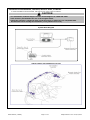
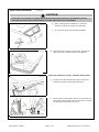
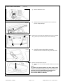
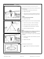
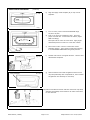
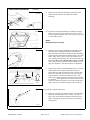
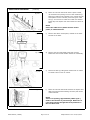
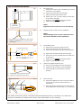
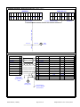
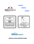
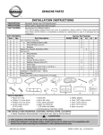
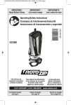
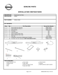
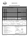
GENUINE PARTS INSTALLATION INSTRUCTIONS DESCRIPTION: Bluetooth Hands-Free (JCI BlueConnect) APPLICATION: Murano without Moon-roof PART NUMBER: BlueConnect Kit (999Q3 MX001) KIT CONTENTS: Item Qty. Part Description A 1 User Interface Assembly A 1 ● User Interface Board (UIB) B 1 ● Standoff Bezel (Cover) 1 C ● Retainer D 1 Hands-Free Module Assembly (HFM) Harness Kit E 1 E 1 ● Wire Harness F 5 ● Cable Ties 2 G ● Posi-Tap H 2 ● Closure Screws (#8x1") 4 I ● Retainer Screws (#6x1/2") J 1 ● Foam Tape Strip (4 Pieces) K 2 ● Round Spacer (#8 7/16"L, 1/4"O.D.) L 1 ● Flocked Tape (1"x1-1/2") M 1 Installation Template-Clear Routing Template N 1 O 1 Installation Instructions Replacement Template P 1 Map Lamp Assembly Back Plate Q 2 A-Pillar Tether Clip A B C S4 X X X 26428 JK00A 76988 1AF0A D I J K L M TOOLS REQUIRED: ● Plastic trim tool ● Hand drill ● Phillips #2 screw driver ● Torque Screwdriver (0-25 in-lbs) ● Side cut pliers ● T-15 Torx screw driver ● Spiral cutting tool ● Compressed air with blow nozzle ● Flex cable (optional) ● SABRECUT Zip® Bit (1/8"metal and plate) ● Safety glasses ● Rectangular Clip Removal Tool ● 3mm (1/8") drill bit NBCI-DIO-MU (1387BC) Service Part Number 999Q3 MX000 S1 S2 S3 X X X X 999Q3 MZ000 X 999Q3 MX000 X X X X X X X X X X X X X 999Q3 VX000 E N F O G P H Q ● 6mm (1/4") drill bit ● Screw Removal & Reinstallation Fixture Page 1 of 18 Nissan Part# J-51033: NOTE: This tool must be used in order to properly install BlueConnect. 999Q3 MX100-II Rev. 8 04/17/2013 PRE-INSTALLATION WARNINGS, CAUTIONS, CRITICAL STEPS, and NOTES: ● Dealer Installation Recommended. Instructions may refer to Service Manual. CAUTION ● For Installation/Technical Support Contact AutoIntelligence at 1-888-454-4440. ● This accessory will eliminate the use of the sunglass holder. ● Check the customer's cell phone make, model and carrier to make sure it is compatible with BlueConnect before starting the installation (www.jciblueconnect.com). INSTALLATION OVERVIEW: System Block Diagram Vehicle outline with installation overview NBCI-DIO-MU (1387BC) Page 2 of 18 999Q3 MX100-II Rev. 8 04/17/2013 INSTALLATION PROCEDURE: 1) Apply parking brake. 2) Confirm the vehicle is no longer in the default shipping state (Extended Storage Switch Pulled Up and BCM in Transit Mode). Failure to confirm the vehicle has been removed from this state will result in the loss of normal vehicle operation. The confirmation requires two checks: 2a) Locate the Extended Storage Switch in the cabin fuse block. Once located, check that it is in the "Customer" position. See below for reference. 2b) Turn the ignition switch from "OFF" to "ON" position. If turn indicators illuminate for approx. 1 minute, the vehicle is in shipping mode. To exit shipping mode, return the ignition switch to "OFF" position. Simultaneously push the wiper and turn signal stalks downward and hold for 2 seconds. Inventory CORRECT INCORRECT >2 Seconds INVENTORY - UP CUSTOMER - DOWN Note: Typical vehicle condition shown above. Switch is easily identifiable by the permanent, push-pull fuse holder. Actual position on the fuse block may vary, vehicle to vehicle. 3) Turn ignition switch to "ON" position. 4) Record the customer radio presets and other presets as required. Preset 1 2 3 4 5 5) Put shift lever in "P" position for A/T and CVT or "1st" for M/T. 6) Turn ignition switch to "OFF" position. Fig. 7a 7) Prepare for installation / disassembly. a) NBCI-DIO-MU (1387BC) 6 Page 3 of 18 Disconnect the negative battery terminal. 999Q3 MX100-II Rev. 8 04/17/2013 INSTALLATION PROCEDURE: (continue) CAUTION ● Take care not to scratch or damage any component during the removal or reinstallation process. ● Trim pieces found to have witness marks or broken clips are not to be reinstalled. Fig. 7b b) Apply masking tape to headliner for protection around all sides of front map lamp assembly. c) Tilt rear view mirror down toward windshield. b) c) Fig. 7d Fig. 7e d) Note: Use caution not to tear, scratch or deform welt. e) Pull driver's front body side welt loose from A-pillar between top of door opening and dash level. f) Remove driver's side A-pillar trim, by prying away from body. Snip A-Pillar Tether Clip from trim cover. Remove clip from body and A-Pillar trim cover. Start here Fig. 7f Protect the left kick panel, left sill plate, left lower Bpillar and center console as shown in illustration. Slide clip tower NBCI-DIO-MU (1387BC) Page 4 of 18 999Q3 MX100-II Rev. 8 04/17/2013 INSTALLATION PROCEDURE: (continue) Fig. 7g g) Remove dash side cover. Fig. 7h h) Reinstall driver's front body side welt on A-pillar to prevent dimple/damage. Beware of dimple/damage to this area. Fig. 8 8) a) Fig. 8a Fig. 9a Remove the front map lamp assembly lens covers. Depress all (4) white clips to lower lamp unit out of assembly. 9) Carefully support lamp/switch assembly, disconnect wire harness for lamp and set aside. Bracket and Back Plate Removal. a) Release roof mount bracket (Plastic Fastener) from roof panel. Note: To release roof mount bracket, pull down firmly (using bracket). CAUTION: Pulling too hard could cause roof panel to cave in. If replacement is necessary use: Part# 73224 1AB0A for Bracket Map Lamp. Part# 15-53 30001 for BRK Clip. NBCI-DIO-MU (1387BC) Page 5 of 18 999Q3 MX100-II Rev. 8 04/17/2013 INSTALLATION PROCEDURE: (continue) Fig. 9b b) Turn anchor 90 degrees counter clockwise and pull down to remove. Repeat this process on the passenger side. Vehicle Front Fig. 9c Note: Position yourself in the vehicle passenger side floor board facing the back of the vehicle for this step. c) Vehicle Front Fig. 10 10) Position Removal & Reinstallation fixture by aligning the left side as shown in Fig. 9a. Roll the fixture up over the top of the roof bracket pressing down until firmly locked in place. Push locator slide into place. Uninstall roof mount bracket by loosening screws on left and right side. Remove fixture & bracket from vehicle by rotating toward the front of the vehicle and down. Retain bracket, leaving connected to the fixture, for reassembly. While in headliner relieve all tabs on the back plate, disengage from Map Lamp Assembly, and remove assembly from headliner. Discard old back plate and replace with new part provided in kit. To remove Back Plate, tilt diagonally and pull through the Map Lamp Assembly opening. CAUTION ● Do not attempt to process or disassemble front map lamp assembly in vehicle. ● Work area should be clean, scratch proof, and free of debris to avoid damage of any component. ● Safety glasses must be worn during front map lamp assembly processing operations. NBCI-DIO-MU (1387BC) Page 6 of 18 999Q3 MX100-II Rev. 8 04/17/2013 INSTALLATION PROCEDURE: (continue) Fig. 12 11) Take map lamp assembly to work area to process. 12) Drill pilot hole for door closure screws on sides of front map lamp assembly. 10mm 20mm 3 a) Mark location of pilot hole for closure screw. b) Repeat on other side. c) Drill through front map lamp assembly and bin door making two (2) pilot holes with 3mm (1/8") drill bit. NOTE: Drill must penetrate both walls. d) Fig. 13 Repeat on other side. 13) Remove sunglass bin door from front map lamp assembly. c) b) #2 a) a) Remove two (2) screws. Retain for reassembly. b) Remove pivot bushing. Retain for reassembly. c) Tilt sunglass bin door up and remove. Set aside. d) Remove and discard pivot spring. NOTE: Work area should be clean, scratch proof, and free of debris to avoid damage of any component. d) Fig. 14 14) Enlarge hole for round spacer on sides of front map lamp assembly. a) Drill pilot hole made in step 12 with 6mm (1/4") drill bit to enlarge. b) Repeat on other side. 6 Fig. 15a 15) Cut opening in sunglass bin door. a) Align and apply clear template (M) to sunglass bin door. M (1) NBCI-DIO-MU (1387BC) Page 7 of 18 999Q3 MX100-II Rev. 8 04/17/2013 INSTALLATION PROCEDURE: (continue) Fig. 15b b) Align and apply metal template (N) on top of clear template. c) Turn on rotary cutter. Recommended RPM range 15,000 to 20,000. d) Test cut in center of sunglass bin door. Check for proper cut feed rate. To minimize bit chatter, adjust RPM accordingly. N (1) Fig. 15d e) d) Test Cut Place spiral bit in center of cutout area. Apply slight downward pressure to start cut in bin door surface. Clean completely e) Move cutter until it comes in contact with metal template opening. Then continue cutting the opening in a CLOCKWISE DIRECTION with gentle pressure. Fig. 15f f) Discard oval section of sunglass bin door. Remove and discard both templates. Fig. 15g g) Clean all debris from inside sunglass bin door & front map lamp assembly with compressed air, then reinstall sunglass bin into assembly for next step. Fig. 16 16) Remove and discard screws and latch from front map lamp assembly with Phillips #2 screwdriver to make access hole for wire harness. #1 NBCI-DIO-MU (1387BC) Page 8 of 18 999Q3 MX100-II Rev. 8 04/17/2013 INSTALLATION PROCEDURE: (continue) Fig. 17a Vehicle Front 17) Install user interface assembly in sunglass bin door. a) Place standoff bezel (B) on sunglass bin door in correct orientation, see drawing. b) Place user interface board (A) on standoff bezel (B) and sunglass bin door in correct orientation, see drawing. B (1) Fig. 17b Vehicle Front NOTE: Flat area on UIB should align with flat area on sunglass bin door hole. A (1) Fig. 17c c) Hold user interface board, standoff bezel, and sunglass bin door together and turn face down on clean surface. d) Place retainer (C) on back side of user interface board in correct orientation, see drawing. e) Place four (4) retainer screws (I) through retainer and insert tip of each screw in the user interface board holes. Start each screw by tightening two (2) full turns with screwdriver. f) Check alignment of user interface board in sunglass bin door cutout. It should be centered and parallel to edge of sunglass bin door. Check for gaps and bezel alignment. g) Follow sequence in drawing and tighten screws to 0.56~0.79 N-m (5~7 inch pounds) using screw torque wrench. Vehicle Front Fig. 17d Vehicle Front C (1) 3 g) #2 1 2 Fig. 17e 4 0.56~0.79 N-m I (4) NBCI-DIO-MU (1387BC) NOTE: DO NOT over tighten screws. Page 9 of 18 999Q3 MX100-II Rev. 8 04/17/2013 INSTALLATION PROCEDURE: (continue) Fig. 18a 18) Reassemble sunglass bin door in front map lamp assembly. a) Pass smaller white connector of wire harness (E) through access hole in front map lamp assembly. Fig. 18b b) Plug wire harness connector into user interface assembly. Press firmly until "click" is heard. Fig. 18c c) Place pivot post end of sunglass bin door in front map lamp assembly pivot hole. Fig. 18d d) Align pivot bushing post with front map lamp assembly pivot hole and insert bushing. Install pivot screws and tighten to 0.45 N-m (4 inch pounds). E (1) #2 NOTE: DO NOT over tighten screws. 0.45 N-m Fig. 18e NBCI-DIO-MU (1387BC) e) Close sunglass bin door taking care to route wire harness through access hole. Page 10 of 18 999Q3 MX100-II Rev. 8 04/17/2013 INSTALLATION PROCEDURE: (continue) Fig. 18f f) Insert two (2) closure screws (H) into two (2) round spacers (K) and install in drilled holes on sides of front map lamp assembly. Tighten to 0.55~0.65 N-m (4.92~5.76 inch pounds). NOTE: DO NOT over tighten screws. 0.55~0.65 N-m #2 K (2) H (2) 75mm Vehicle Front Fig. 19a Vehicle Front Fold adhesive backing on hands-free module assembly (D) back and hold in place. Place hands-free module assembly between the headliner and roof panel on passenger side of opening approximately 75mm (3'') inward. Align with adhesive tape down toward headliner. b) Position hands-free module against header beam. Pull adhesive backing to remove and press firmly into place against the headliner being careful not to crease the headliner. Place new Back Plate in headliner and attach lamp harness to back plate. D (1) Fig. 19b Header beam a) Back Plate Driver Side Fig. 20a Fig. 20b 20) Install front map lamp assembly. a) Route wire harness power/ground leads toward driver side of vehicle and apply flocked tape (L) to secure, as shown. b) Route wire harness power/ground leads between headliner and roof beam above rear view mirror and let hang down. Front NBCI-DIO-MU (1387BC) Page 11 of 18 999Q3 MX100-II Rev. 8 04/17/2013 INSTALLATION PROCEDURE: (continue) Fig. 20c Fig. 20d c) Support front map lamp assembly and connect wire harness large connector to hands-free module assembly. d) Insert front map lamp assembly in headliner opening taking care to route wire harness out of way. Insert two (2) alignment tabs at rear, then insert two (2) clips in roof. Snap in place. NOTE: Route harness out of way. Fig. 20e e) Support front map lamp assembly and headliner with one hand while reaching through the lamp opening. Align the back plate with the front map lamp assembly, press downward toward the assembly flange, then click tabs in place. Take care to route wire harness out of way. Repeat this step all the way around the front map l bl ensuring i th ll ttabs b are ffully ll engaged d lamp assembly thatt all (hear click). Perform inspection to see that there is no gap, and condition is the same as prior to installation. Fig. 20f f) Using screw removal and reinstallation fixture, reinstall roof bracket onto back plate. Bracket and fixture should still be together with each screw in place. Align fixture, see Fig. 20e. Roll the fixture up over the top and press down. Push locator slide into place. Turn each screw counter clockwise to ensure proper seating on assembly, then tighten screws. Remove fixture from vehicle by rotating toward the front of the vehicle and down. Push clip on bracket assembly into roof panel. Vehicle Front Fig. 21a 21) Route wire harness lead wires. a) Route wire harness (E) lead wires from front map lamp assembly area behind sun visor anchor, to top of Apillar. Tuck wires between headliner and vehicle roof beam. Avoid pinching wires near anchor by following dotted arrow. E (1) NBCI-DIO-MU (1387BC) Page 12 of 18 999Q3 MX100-II Rev. 8 04/17/2013 INSTALLATION PROCEDURE: (continue) b) Fig. 21b F (4) Route wire harness lead wires down A-pillar to dash, use forward most opening in front of flat metal facing. Make sure lead wires are parallel to the vehicle harness and topside. Secure to anchor points using four cable ties (F). Trim excess on cable ties. Install new A-Pillar Tether Clip onto A-pillar trim then install into vehicle APillar. NOTE: Secure the cable ties to plastic harness anchor points, to vehicle harness. Fig. 21c c) Remove fuse block access panel, located on the lower left side of the dash. Fig. 21d d) Remove the two under dash panel bolts (10mm) behind the hood release handle. Retain for reassembly. e) Relieve six tabs by pulling down toward rear of vehicle to release. Place in floor of vehicle. f) Route wire harness lead wires between the A-pillar and dash mounting bracket following the same path as the vehicle harness. #2 Fig. 21e Fig. 21f NOTE: There is an opening, approximately 19mm (3/4") wide for the harness to pass through. Make sure to route wire harness through this cavity and then to the fuse block area. NBCI-DIO-MU (1387BC) Page 13 of 18 999Q3 MX100-II Rev. 8 04/17/2013 INSTALLATION PROCEDURE: (continue) CAUTION ● Color(s) given in illustration(s) are for reference only. Use location(s) where color deviates. ● If a vehicle wire is being used by another accessory and a Posi-tap is present, tap the accessory wire, not the vehicle wire. ● Do not pinch the harness between trim when re-installing vehicle trim pieces. 22) a) Attach the yellow ACC wire (BlueConnect) to the Red (Vehicle) wire in MA03 location of connector NS06FWM2 in the fuse block-junction block (J/B). Attach the red B+ (BlueConnect) wire to the Yellow (Vehicle) wire in AA26 location of connector NS10FW-CS in the fuse block-junction block (J/B). See Posi-tap Installation Detail, steps 1 - 5, on page 15. Fig. 22a Back of Connector Attach B+ Wire here. Back of Connector Attach ACC Wire Here G (2) Fig. 22b b) Apply foam pad (J) to each posi-tap. See Posi-tap Installation Detail, step 5, on page 15. c) Remove tape from black ground wire eyelet and discard. Torx #15 Ground screw is next to the lower left side of the fuse block area. Route black ground wire with eyelet to screw location, insert screw in eyelet at 10 o'clock position and insert in original location. Attach harness to vehicle with cable tie (F). J (2) Fig. 22c NOTE: DO NOT over tighten screw. #15 F (1) NBCI-DIO-MU (1387BC) Page 14 of 18 999Q3 MX100-II Rev. 8 04/17/2013 POSI-TAP INSTALLATION DETAIL: Fig. 1 c) 1) e) b) 12.7 mm Vehicle Connector Tap vehicle wire. a) Identify and confirm (test if necessary) the correct vehicle wire to be tapped. b) c) d) Remove cap (slot side) from tap body. Slide cap around single vehicle wire. Position cap 0.5" (12.7mm) away from the back of the vehicle connector. e) f) Tighten the tap TIGHT with finger pressure. Tighten by another quarter turn. NOTE: Figures are not to scale. Do not re-use the tap. Fig. 2 2) Inspect the tap to ensure correct installation. NOTE: Avoid putting pressure on the vehicle wire and tap for the remainder of the installation. i. Straight and evenly spaced all the way around ii. Tight and minimize gap (wire jacket should be crushed) Fig. 3 3) e) Insert wire to here c) a)) d) f) Tighten Tap accessory wire. a) Remove tap (non-pierce) side from tap. b) Remove the protective stub from the wire. c) Insert wire through the non-pierce side opening. d) e) Spread the individual strands into fan shape. Insert wire into the tap body and ensure that it is all the way in. f) g) Tighten the tap TIGHT with finger pressure. Tighten by another quarter turn. Fig. 4 4) Confirm the tapped accessory wire. a) Pull on the wire lightly to ensure connection. b) Inspect the tap to ensure correct installation. c) Test the signal to ensure that it is working properly. Fig. 5 5) Secure the tap. a) Secure the tapped wire on the non-pierce side to the body of the tap with electrical tape (≥ 2 revolutions). i. Straight and evenly spaced all around ii. Tight and no gap and test the signal Vehicle Harness b) a) b) Secure the body to harness where vehicle wire is being tapped with electrical tape (≥ 2 revolutions). Accessory Posi-TapTM is protected by patent # 5,228,875 5,695,369 5,868,589 6,692,313 Jap 2881414 Aus 708700 Tia 103534 Can 2204826 Mex 200626 Korea 477279 China Z197105562.9 & others pending. NBCI-DIO-MU (1387BC) Page 15 of 18 999Q3 MX100-II Rev. 8 04/17/2013 For Installation/Technical Support Contact AutoIntelligence at 1-888-454-4440. ACCESSORY CHECK: Connect the battery negative terminal and tighten the nut to 5.4 N-m (47.8 lb-in) Check all Critical Installation Steps. Check all torque values. Retainer screws (I) tighten to 0.68 N-m (6 lb-in) average. (see step 17e, page 9) Allowable range for torque is 0.56~0.79 N-m (5~7 lb-in). Pivot screws tighten to 0.45 N-m (4 lb-in). (see step 18d, page 10) Closure screws (H) tighten to 0.60 N-m (5.3 lb-in). (see step 18f, page 11) Allowable range for torque is 0.55~0.65 N-m (4.92~5.76 lb-in). Battery negative cable tightens to 5.4 N-m (48 lb-in) average. (see step 7a, page 3) Verify all wiring is secure and not exposed. Check Posi-Tap by pulling lightly on wires to confirm that tap point is secure and visually confirm that single wire is tapped. Verify the correct wire is tapped. Trim all excess cable ties flush. Turn ignition switch to "ACC" position. Confirm accessory main features and functions. See diagnostic flow chart on the next page for troubleshooting. Confirm accessory voice prompt current language is set to English. See diagnostic flow chart function check on the next page. RE-INSTALLATION OF REMOVED PARTS: Re-install left visor anchor first to properly position headliner. Re-install flat wire harness, connecting it to the back plate of the map lamp assembly, following original routing. (see step 8a, page 5) Re-install all removed vehicle parts. Refer to the vehicle service manual for more details. CAUTION Use caution when re-installing interior components to avoid damage, scratches, or breaking of mounting clips. Refer to the vehicle service manual for more information. FINAL INSPECTION: Verify no rattles exist by tapping on the Headliner, A-Pillar, and Map Lamp. Verify re-installed trim parts for proper flush fit (no gap, no waviness, etc.). Verify all clips are fully engaged and locked. Verify re-installed trim parts are free from cracks, scratches or stress marks. Verify vehicle headliner, seat, steering wheel, center console, floor carpets, etc. are not soiled. Verify interior and exterior is not damaged. Turn ignition switch to "ON" and confirm proper operation of Vehicle Systems If equipped, verify all window and sunroof one touch operation and perform the reset procedure if necessary. Refer to the vehicle service manual for more details. Confirm proper audio function (AM, FM, SAT, CD and AUX). Re-program radio presets and other vehicle settings to the recorded settings. No need to do this step if the extended storage switch is placed in the "inventory" position. Start engine and verify that there are no new Diagnostic Trouble Codes. Turn ignition switch to "OFF". Place the Owner Manual and Quick Reference Guide in the glove box. If this vehicle will be returned to a dealer lot or showroom for an extended period of time, be sure the extended storage switch is placed in the "inventory" position. Refer to the Extended Storage Switch verbiage at the beginning of the 'INSTALLATION PROCEDURE' section. NBCI-DIO-MU (1387BC) Page 16 of 18 999Q3 MX100-II Rev. 8 04/17/2013 DIAGNOSTIC FLOW CHART: For Installation/Technical Support Contact AutoIntelligence at 1-888-454-4440. Function Check Items To Be Checked Results of the Check BLUECONNECT POWER CHECK: Turn the ignition to ACC position. Check BlueConnect operating buttons. The white operating buttons on the BlueConnect User Interface assembly should illuminate white. Confirm the BlueConnect works when the key is in the ACC position. BLUECONNECT FUNCTION: Allow 15 seconds after ignition The blue center bar should illuminate blue each time button is pushed and volume tone should increase or decrease. is turned to ACC position for unit to complete self check. Push the volume (+) button three times. Repeat for volume (-) button. SPEAKER FUNCTION: With ignition turned to ACC position, The blue center bar should illuminate blue. "BlueConnect Ready" push the phone button to activate the system. should be heard. Push the phone button again to cancel when done. MICROPHONE FUNCTION: With ignition turned to ACC position, push the phone button to activate the system. Listen for voice prompt and BEEP, then say "Setup." BlueConnect should recognize and accept voice command. "Select one of the following..." should be heard. Push the phone button again to cancel when done. CURRENT LANGUAGE: With ignition turned to ACC position, BlueConnect voice prompt should be in English and "BlueConnect push the phone button to activate the system. Listen to Ready" should be heard. If Spanish or French, listen for beep, language voice prompt. then say "English." Listen for confirmation prompt and answer "Yes." Push the phone button again to cancel when done. BlueConnect® UIB (User Interface Board) 1 6 2 5 4 1) Phone Button or Activation/ Deactivation Button ● ● ● ● ● Push to set up and program unit. Push to receive an incoming call. Push to make a call if not on a call. Push to end a call. Push to accept an incoming call when on another call. 3 4) Blue L.E.D. Light ● A Blue light comes on indicating that the unit is activated or when there is an incoming call. It also comes on when you are on a call. 5) Voice Recognition (VR) or Barge-In Button ● Push to input a command without having to listen for a prompt. ● Push & hold the button until you hear a beep, while the BlueConnect is in standby. The "SYSTEM OFF" feature is activated. ● Push and say "TRANSFER CALL". This allows you to transfer your call back to your cell phone in the event you want privacy or are exiting the vehicle. Repeat to transfer call back to BlueConnect. 2) Volume Up & Down Buttons ● Push (+) to increase the volume. ● Push (-) to decrease the volume. ● Push either button to the desired volume level when the unit is not activated. Audible beeps indicate the current volume level. ● Push and say "MUTE" to mute the phone. ● Push to send the DTMF tones. (Dual-Tone Multi-Frequency) tones. 6) Directional Microphone 3) Speaker NBCI-DIO-MU (1387BC) Page 17 of 18 999Q3 MX100-II Rev. 8 04/17/2013 HARNESS DIAGRAM: BlueConnect Harness (999Q3 VX031) 1565380-1 1 PADP-20V-1-S 5 15 16 17 19 25 26 Module 14 2 6 10 28 1 5 9 50 mm (tape) 14 16 18 20 11 13 User Interface 1810 mm (flock tape) 275 mm (tape/flock tape) 100 mm GND Eyelet 100 mm 100 mm 1565380-1 MIC IN (+) Pin Pin PADP-20V-1-S 14 MIC IN (+) 1 MIC IN (-) 15 13 MIC IN (-) MIC SHLD 16 NC CUT SHLD AUDIO (+) 5 18 AUDIO (+) AUDIO (-) 19 20 AUDIO (-) UI BUTTON 17 16 UI BUTTON UI ENABLE 25 11 UI ENABLE ACCA 28 5 ACCA GNDA 26 9 GNDA BATA 14 1 BATA 2 BAT 10 GND Vehicle Splice: Connector NS10FW-CS-Pin AA26 6 GND Eyelet: See Fig. 22c. NBCI-DIO-MU (1387BC) ACC Color Red Black Bare / Drain Light green Dark green Light blue Gray Orange Brown Pink Red Black Yellow Size 22 22 22 22 22 22 22 22 22 22 22 22 22 awg awg awg awg awg awg awg awg awg awg awg awg awg Ref.Value Battery voltage ~0V Battery voltage Vehicle Splice: Connector NS06FWM2-Pin MA03. Page 18 of 18 999Q3 MX100-II Rev. 8 04/17/2013