1
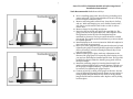
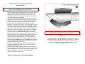
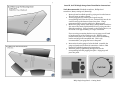
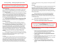
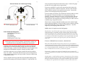
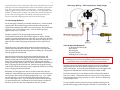
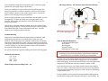
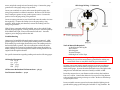
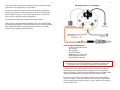
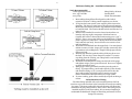
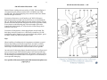
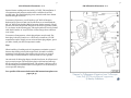
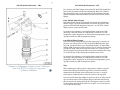
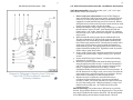
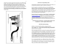
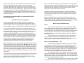
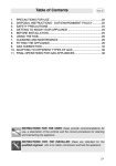
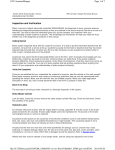
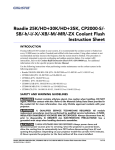
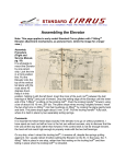
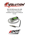
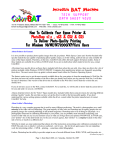
2
42 Draft Designs
Jetta IV, Golf IV Triple Gauge Panel Installation Instructions
Tools Recommended: Radio Removal Keys
Gauge Solution Installation Instruction Manual
1.
* Stewart Warner Gauges / VW Vehicles *
The following guide contains guidelines, tips and tricks for installing your
42 gauge solution. Note the index below to begin!
As always, read all instructions prior to installation. Do not deviate
from basic wiring or mounting instructions. Always disconnect
battery ground before making any electrical connections. If in doubt,
please email 42 Draft Designs [email protected] or seek
professional help.
2.
3.
4.
5.
Mounting
Mk4 Triple Gauge Panel 2-3
Mk4 Aluminum Double & Triple Gauge Panel 4
Mk4 A-Pillar Gauge Pods 4-5
B5 A-Pillar Gauge Pods 7-9
Single Gauge Panel 10
VDO Gauge Wiring
VW Tips and Tricks 11-12
Perfect Match LEDs 12-13
Boost Gauges 14
Air-Fuel Ratio Gauges 15-17
Oil and Water Temp Gauges 18-19
Oil and Fuel Pressure Gauges 20-21
Voltmeters 22-23
EGT (Pyrometer) Gauges 24-25
Tubing and Sending Units
Boost Tubing Kits 26-28
Oil Sender Placement
1.8T 29-30
2.0 31-32
VR6 33-35
TDI 36-37
Oil Pressure Relocation Kit Instructions 38-39
Water Temp Sending Units 40
EGT probe mounting 40-41
Fuel Pressure Sending Units 41-42
Boost Gauge Troubleshooting 42-43
Prior to installing gauge panel, have all wires and tubing run to
gauges and tested. It is recommended that all wires be left long
to free workspace behind the panel.
Remove radio using radio removal keys. Snap keys in. Pull up
and out. With radio hanging out, cover climate controls with a
soft cloth to avoid scratches. Push in tabs on side of radio to
remove keys.
Remove storage bin by pulling straight out.
Install center gauge into panel using standard U brackets
included with most aftermarket gauges. If your 2 1/16 gauges did
not come with mounting brackets, fabricate some, or order the
standard brackets. Tighten center gauge tight by hand. Over
tightening gauge will cause panel to bend.
The outer mounting brackets must be modified to install the
triple gauge panel. There are two ways to modify the brackets to
secure the panel.
As illustrated to the right, you can simply use the outer leg of the
mounting bracket to secure the gauge panel in place. To do this, you will
need to cut the outer leg 1/8” shorter than the inner leg, and bend
outward to extend beyond the side of the gauge panel. When installing,
you will need at least ¼” of slack between the mounting bracket legs and
the appropriate ribs along the inside of the center console. If need be, cut
the bottom of the legs proportionally to allow enough slack.
Similar to the above method, version 2 uses a modified outer bracket.
In this case, instead of cutting 1/8” off the outer leg, a 1/8” long 90º bend
is made to secure the gauge panel to the center console. When installing,
you will also need ¼” of slack between the mounting bracket and the rib
of the center console. Modify accordingly.
6. Install modified brackets and leave loose, allowing at least ¼”
slack between panel and brackets. Install all wires and sit panel
in place. Once again, test all connections and gauges.
7. Reaching up from the radio slot, position either modified bracket
onto the inner rib of the center console, and tighten the
corresponding nut. Repeat for other side. Center panel, and
align so the cup holder opens freely. Tighten nuts on outer
brackets tight, by hand. Replace radio and push gauge panel
down against radio face. When positioning gauge panel into
place, it helps to work one side at a time aligning the panel, and
working the brackets into place. Good luck and have fun!
3
4
Jetta IV, Golf IV Aluminum Double & Triple Gauge Panel
Installation Instructions
Tools Recommended: Radio Removal Keys
8. Prior to installing gauge panel, have all wiring and tubing run to
gauges and tested. It is recommended that all wires be left long
to free workspace behind the panel.
9. Remove radio using radio removal keys. Snap keys in. Pull up
and out. With radio hanging out, cover climate controls with a
soft cloth to avoid scratches. Push in tabs on side of radio to
remove keys.
10. Remove storage bin by pulling straight out.
11. Notice the ribs on the left and right of the open DIN slot. The
gauge panel will sit flat against these ribs. The backplate will sit
flat against the back of the ribs. The backplate has been
machined for clearance. The larger notches should be oriented
downwards. The smaller notches and thinner top contour should
be oriented upwards.
12. Install backplate in the correct orientation. Hold the backplate in
place and install the gauge panel.
13. Insert your center gauge through both panels and secure by hand
tightening the gauge’s mounting bracket against the backplate. It
may be necessary to trim the mounting brackets if they are too
long. All gauges differ.
14. With the center gauge in place, make any adjustments to the
fitment of the gauge panel. If it seems the panel is sitting too low,
you may have the backplate installed upside down. The top of the
backplate has been machined so that the gauge panel will sit at
the correct height.
15. Install the remaining gauges by inserting them through both
panels and hand tightening the mounting brackets. Go back over
all the gauges and tighten them up – by hand! Tools should not
be necessary for tightening the gauges in place.
16. Connect any wiring or tubing to the gauges at this time. Be sure
to test all lighting and gauge functions. Route any extra wiring or
tubing up high and push back into the dash. No wiring should
hang down and interfere with the radio. Replace radio by sliding
back into place.
5
6
A-Pillar Gauge Pod Installation Instructions
Jetta IV, Golf IV
Some 2001 and later Volkswagen vehicles use A-pillar mount airbags. Apillar pods should NOT be used on these vehicles.
1.
2.
3.
4.
5.
6.
Remove A-pillar trim by locating upper seam and prying outward.
Use clean hands and avoid using any type of tool to pry. Once a
small opening is created at the pillar top, use some force to
release the 3 plastic mounting clips. With A-pillar cover pulled
out, lift upwards remove completely.
On a clean surface, test fit gauge pod on pillar trim. Notice the
pod will only fit in the lowest position. Line edges up and wrap
the fabric tabs over pillar trim. Use sharp scissors to precisely
notch the tabs where any protrusions of the pillar trim exist.
Fit gauge and secure using the gauge’s supplied mounting
hardware. Decide on a wiring route. Wire and tubing can be run
under the molded wire trail on the bottom of the pod. Install
any tubing or wiring at this point. The gauge and lighting (LEDs
have polarity!) should be tested prior to permanent installation.
With gauge secured, mount pod on the A-pillar trim. The three
fabric tabs should be wrapped tightly and secured to the back of
the A-pillar trim. For a permanent installation, use contact
cement or glue of choice. For a temporary installation, use foil
tape or duct tape to secure the fabric tabs to the back of the trim.
During mounting, hold pod tightly against trim to assure a
flawless seam between pod and trim. Consider using tape to
hold tabs in place if gluing tabs one by one. Remember, tabs
should be wrapped tight and glued to the back of the stock trim.
This installation should make no permanent modification to the
visible area of the stock A-pillar trim.
With pod mounted and glue dry, route wires and tubing down
the side of the dashboard. Install wires and tubing based on
manufacturer’s instructions.
Reinstall A-pillar trim by inserting bottom section between the
frame, dashboard, and weather stripping. Fold in and position
based on the location of the upper seam. When in position, push
trim back into place. Use force to snap mounting clips in
securely. Good luck and have fun!
Please view diagram on the following page!
Some 2001 and later Volkswagen vehicles use A-pillar mount airbags. Apillar pods should NOT be used on these vehicles.
Adhesives
Contact cement offers the best adhesion, but is difficult to remove.
To change the gauge or lighting LED the pod will need to be removed.
Keep this in mind when choosing an adhesion method. Many
customers have found duct tape and foil tape to hold well while
offering a removable adhesion.
7
8
Some 2001 and later Volkswagen vehicles use A-pillar mount airbags. Apillar pods should NOT be used on these vehicles.
flawless seam between pod and trim. Consider using tape to
hold tabs in place if gluing tabs one by one. Remember, tabs
should be wrapped tight and glued to the back of the stock trim.
No adhesive or screws should be used to fasten the gauge pod to
the visible area of the stock A-pillar trim.
A-Pillar Gauge Pod Installation Instructions
Passat B5
17. Remove a-pillar trim by locating upper seam and prying outward.
Use clean hands and avoid using any type of tool to pry. Once a
small opening is created at the pillar top, use some force to
release the 4 plastic mounting clips. With a-pillar cover pulled
out, lift upwards and remove completely.
18. On a clean surface, lay out gauge pod and a-pillar trim. There
will be a faint imprint on the a-pillar trim outlining the top of the
dashboard. The bottom (plastic) edge of the gauge pod should be
positioned to follow this line and rest on the dashboard. The
dashed line in the drawing below represents the top of the
dashboard.
19. Line edges up and wrap the fabric tabs over the a-pillar trim.
Use sharp scissors to precisely notch the tabs where any
protrusions of the pillar trim exist. Use masking tape to secure
fabric tabs during test fitment. With gauge pod positioned, test
fit the assembled gauge pod and a-pillar trim to check fitment.
Adjust as required.
20. Once you have the pod positioned correctly, begin to mark the apillar trim for drilling.* See diagrams below for approximate
positioning of the hole to be drilled. The hole should be at least
3/8” in diameter to accommodate tubing and wiring. The
position of the hole should be such that the tubing can easily
route from the gauge without any sharp bends. Before drilling
the hole, be sure you are happy with the positioning of the gauge
pod and have test fitted the assembled unit in the car with gauge
and fittings installed. The hole should not be visible with gauge
pod installed. Measure twice, drill once.
21. Fit gauge and secure using the gauge’s supplied mounting
hardware. Some gauges’ u-brackets may need to be modified to
fit within the tight constraints of this installation. Simply bend
the u-bracket to clear the a-pillar trim. Install any fittings,
tubing or wiring at this point. The gauge and lighting (LEDs
have polarity!) should be tested prior to permanent
installation. This is also a good time to be sure your gauge is
clocked correctly.
22. With gauge secured, mount pod on the a-pillar trim. The three
fabric tabs should be wrapped tightly and secured to the back of
the a-pillar trim. For a permanent installation, use contact
cement or glue of choice. For a temporary installation, use foil
tape or duct tape to secure the fabric tabs to the back of the trim.
During mounting, hold pod tightly against trim to assure a
Adhesives
Contact cement offers the best adhesion, but is difficult to remove.
To change the gauge or lighting LED the pod will need to be removed.
Keep this in mind when choosing an adhesion method. Many
customers have found duct tape and foil tape to hold well while
offering a removable adhesion.
23. With pod mounted and glue dry, route wires and tubing down
the side of the dashboard. Install wires and tubing based on
manufacturer’s instructions.
24. Reinstall A-pillar trim by inserting bottom section between the
frame, dashboard, and weather stripping. Fold in and position
based on the location of the upper seam. When in position, push
trim back into place. Use force to snap mounting clips in
securely. Good luck and have fun!
*Drilling
Fitment between the dashboard and a-pillar trim in the B5 is
extremely tight. Boost gauge tubing cannot be routed between the
pod and pillar trim. It is physically impossible to squeeze anything
extra in this area. In order to run tubing to a boost gauge, a hole must
be drilled in the stock pillar trim.
If installing a gauge other than boost, it may be possible to run wires
without drilling a hole in the a-pillar trim. If running only wires to
the gauge, installation can be attempted by routing the wires between
the pod and the pillar trim. Any extra wires in this area will cause a
tighter fitment in the area between the a-pillar trim and dashboard.
Please view diagrams to the right!
9
10
Jetta III, Golf III Single Gauge Panel Installation Instructions
Tools Recommended: Flat head screwdriver, Phillips head
screwdriver, Rotary cutting tool (Dremel®)
1.
Remove heated seat blank panels by prying out from the bottom.
They will snap out when released.
2. Test fit gauge panel by inserting the long tab into the
corresponding hole below the air vent. Push tab fully into the air
vent hole and pop the bottom of panel into place. Using a
permanent marker, trace the gauge hole. Remove panel.
3. Remove the gauge cluster screw using a phillips head screwdriver.
Also remove the metal clip behind the screw by prying out with a
flathead screwdriver. Using a Dremel or other cutting device, cut
the traced circle approximately 1/8” larger in diameter.
If you are using a mounting bracket on your gauge you will need
to cut the majority of the console area out. With the gauge
installed in the panel you will need room to clear the mounting
bracket and snap in the assembled unit. This is only
recommended if your gauge fits loose in the panel.
4. Route wires from the gauge to below the dash. Assemble the
gauge and panel test all electrical connections. Refer to VDO
manual for individual gauge wiring instructions.
5. Install the panel by again fitting the upper tab into the
corresponding hole and popping into place. Align gauge and
press into panel.
MK3 Single Gauge Panel – Cutting Detail
11
SW Gauge Wiring – Volkswagen Specific Tips & Tricks
Always test your connections using a test light or multimeter before
connecting any wires! Disconnect battery ground before making any
connections! Your car may differ from the given instructions!
Lighting Circuit
When wiring the lighting circuit of your gauges, it’s best to wire
them into your car’s existing lighting circuit. This way the gauges will
illuminate and dim with the rest of the dash. To do this, you’ll need to tap
into the dimmer switch.
In the mk4 chassis the dimmer switch wiring harness consists of
3 wires. The brown wire is ground, gray wire is incoming power and the
white/blue wire is outgoing power. Tap the white/blue wire using a
wiretap or by stripping a small portion of the wire and soldering in your
power wire. Using 42’s wiring kit you’ll be connecting the white wire to
the white/gray wire of the dimmer switch.
In the mk3 chassis the dimmer switch is built into the headlight
switch. The gray/blue wire located in position 1 is outgoing power. Tap
this wire and connect it to the white wire of your 42 lighting harness.
Switched 12v Power
To power your gauges you’ll need a switched 12 volt source.
When connected to the correct power source your gauges will be active
only with the ignition on and your battery will not be drained.
In the mk4 chassis a switched 12v power source can be found on
the relay block under the dash. To access this block, remove the left
dashboard trim panel and the rubbery panel above the pedal cluster.
Above the clutch pedal you’ll find a relay block consisting of 5-6 relays.
Each relay has a studded terminal with a 10mm nut. The relay labeled
75X should be hot with the ignition on or engine running. You may
connect your red power wires to this relay using the included ring
terminals.
In the mk3 chassis you may find switched 12v power at the fuse
box. Use a test light or multimeter to locate a fuse which is powered with
the engine running and not powered with the engine off. Tap the
powered wire as it exits the fuse box.
Ground
Ground is a simple connection in any VW. Because they use a
common chassis ground, all you have to do is locate a screw that connects
to the chassis. In the mk3 and mk4 chassis, a convenient location is the
dashboard support. With your lower dash panels removed, locate a
screw which connects the plastic dash panels to the metal dashboard
support. Remove the screw and sand any paint of corrosion off the metal
12
to ensure a good connection. Then, ground your wire using the included
ring terminal.
Firewall
In the mk4 chassis there are 2 options for running wires through
the firewall. On throttle by cable cars you’ll need to run your wires
through the firewall with the main wiring harness. You can poke through
using a long metal rod or coat hanger. On throttle by wire cars there is
an empty grommet above the throttle pedal. This grommet is located
where a throttle cable would typically be located. Running wires through
this grommet is ideal.
Also, you may choose to run wires through where the hood
release cable enters the rain tray. If you do run wires through this
grommet, be sure to poke a hole in the grommet and feed the wires
through the grommet. Rainwater will enter the cabin if the grommet is
not installed correctly.
In the mk3 chassis there is an empty grommet above the clutch
pedal. Running wires through this grommet is ideal.
SW Perfect Match LED Installation Instructions
* Perfect Match LEDs should NEVER be powered without a 42 Draft
Designs Power Regulator!
**Power Regulator 12 volt input MUST be vehicle dimmer switch!
***Any other connection to power voids warranty immediately!
Tools Recommended: Wire Cutter, Wire Stripper, Terminal Crimper,
Small Flat-Head Screwdriver
1.
2.
3.
4.
5.
Remove any interior panels necessary to access the dimmer
switch, common ground, and gauge mount. Locate the output
wire of your dimmer switch and a common ground.
Using the included 22 gauge wire, tap the output wire of your
dimmer switch and connect to the appropriate terminal of the
power regulator.
Using the included 22 gauge wire and ‘red’ ring terminal, connect
the power regulator to a common ground.
Remove SW light bulb socket and remove light bulb. Install PM
LED by pushing directly into lamp socket.
Using 2 pieces of included 22 gauge wire and 2 ‘red’ butt
connectors connect one LED & lamp socket to the power
regulator. Positive and negative power terminals are clearly
labeled.
13
6. Apply power to the regulator by turning on the vehicle’s lights.
LED should light immediately. If not lit, remove the bulb from
the lamp socket and rotate 180˚.
7. Install up to 3 more LEDs as needed.
8. Mount power regulator in a solid location to ensure the best
electrical connection. It is recommended that the power
regulator be isolated from the gauge panel / pod.
14
Stewart Warner Boost Gauge Wiring
Installation Tips & Precautions! :
•
•
•
•
For best results, we recommend the connection to the dimmer
switch output wire be soldered. Simply wrapping wires together
is far from ideal.
Never connect power regulator to vehicle common 12 volt power.
The dimmer switch provides the regulator with a clean 12 volt
power source. Vehicle common 12 volt is typically 14+ volts and
will destroy this product!
Never connect more than one LED to a set of +/- terminals. This
regulator will power 4 LEDs – no more! Each set of terminals
provides one LED with regulated power.
Do not over tighten the power regulator screw terminals. Screw
terminals are not head studs, they are just electrical connections!
Last but not least, please follow these instructions and pay
attention to the warnings! We don’t provide these
instructions for our health – we write them to ensure you, the
customer is able to install our product flawlessly the first time
and avoid common mistakes. Good Luck and Have Fun!
Tools & Materials Required:
42 Draft Designs Wiring Kit
Wire Cutters
Wire Strippers
Terminal Crimper
Soldering Iron or Wire Taps
Always test your connections using a test light or multimeter before
connecting any wires! Disconnect battery ground before making any
connections! Your car may differ from the given instructions!
To begin, remove any interior panels necessary to access your dimmer
switch and ground. Route the white 18 gauge wire from your dimmer
switch to the gauge. Connect the white and black wires to the light socket
using the two included butt connectors. Install your bulb or LED.
Locate the output wire on your dimmer switch and strip the insulation
from a ¼” section. Connect the white wire from your 42 wiring harness
to the stripped section using a wire tap or solder. Be sure to shrink wrap
or tape any bare wires.
Locate a suitable common ground and connect using the included ¼”
ring terminal. Be sure to strip back enough wire and securely crimp.
With both wires connected and bulb installed, turn on the vehicle’s lights
and test the gauge lighting. If using an LED, be sure to check for polarity.
If the LED doesn’t light, remove and rotate the bulb 180˚.
For tubing kit instructions see pages 26-28
15
Stewart Warner Air-Fuel Gauge Wiring
16
sure to strip back enough wire and securely crimp. Connect the gauge
ground wire to the gauge using a ring terminal.
Locate your switched 12v source and connect the positive gauge wire
using a ring terminal or soldered connection. Be sure to use an inline
fuse of 10amps or greater on any positive power source. Connect the
positive wire to the gauge using a ring terminal.
Locate an empty grommet in your firewall and route the sender wire into
the engine bay. Connect the sender wire to the gauge using a ring
terminal. Locate the output wire on your 1 volt oxygen sensor and strip
the insulation from a ¼” section. Connect the gray wire from your 42
wiring harness to the stripped section using a wire tap or solder. Be sure
to shrink wrap or tape any bare wires.
With all wires connected and bulb installed, turn on the vehicle’s lights
and test the gauge lighting. If using an LED, be sure to check for polarity.
If the LED doesn’t light, remove and rotate the bulb 180˚. Start the
engine to power the gauge and test the unit.
Which wire do I tap for my air-fuel gauge?
Tools & Materials Required:
42 Draft Designs Wiring Kit
Wire Cutters
Wire Strippers
Terminal Crimper
Soldering Iron or Wire Taps
Always test your connections using a test light or multimeter before
connecting any wires! Disconnect battery ground before making any
connections! Your car may differ from the given instructions!
To begin, remove any interior panels necessary to access your dimmer
switch and ground. Route the white 18 gauge wire from your dimmer
switch to the gauge. Connect the white and black wires to the light socket
using the two included butt connectors. Install your bulb or LED.
Locate the output wire on your dimmer switch and strip the insulation
from a ¼” section. Connect the white wire from your 42 wiring harness
to the stripped section using a wire tap or solder. Be sure to shrink wrap
or tape any bare wires.
Locate a suitable common ground and connect both the lighting circuit
ground and the gauge ground using the included ¼” ring terminals. Be
The black one. On all VW/Audi oxygen sensors and most others there
will be four wires - one black, one gray, and two white. The two white
wires are the heater wires. The gray wire is incoming power. The black
wire is signal output. You need to tap the black wire of your sensor after
is crosses over to the ECU wiring harness. Don't tap the black wire itself
or you will have to remove your tap every time you need to take the
sensor off.
I have a wideband front 02 sensor, what do I do?
Many mk4 VWs and other factory turbo cars have a 5 volt wideband
oxygen sensor in the front position of their exhaust. The wideband sensor
can be identified by having 6 or 8 wires. The rear sensor should always be
a 0-1 volt narrowband sensor, identified by 4 wires. If you find that you
have a wideband front o2 sensor, you have two options:
First option – tap the rear o2 sensor. Tapping the rear o2 sensor will
result in slightly delayed readings due to it’s presence behind the catalytic
converter.
Second option – install another o2 sensor. Any generic 0-1volt o2 sensor
will do the job. You can use any VW o2 sensor or any domestic o2 sensor.
There are 1 wire and 4 wire 0-1v o2 sensors available. The 1-wire sensor
is a GM part. It is grounded to the exhaust, so all you will need to do is
17
connect the wire to the air-fuel gauge. This sensor will take longer to read
when the car is first started because it relies on the exhaust gases to heat
it up. The 4 wire sensor will have 4 connections – incoming 12v power,
outgoing signal, and two heater wires. The sensor is also grounded to the
exhaust. To connect this correctly, you will need to connect switched 12v
power to the incoming power wire and the two heater wires. You will
need to connect the outgoing power wire to the air-fuel gauge.
18
SW Gauge Wiring – Oil Temp & Water Temp Gauges
Air-Fuel Gauge Behavior
An air-fuel gauge is basically a voltmeter attached to a 1 volt narrowband
oxygen sensor. Narrowband oxygen sensors measure the amount of
oxygen in the exhaust gases within a very narrow range. The useable data
range of a 1 volt oxygen sensor is 0.00 -1.00 volt which represents
approximately 14.4 – 15.0 AFR.
The basic operation of an air-fuel gauge demonstrates the
communication between the ECU and the engine. In order to fuel the
engine at a perfect stoichiometric air-fuel ratio of 14.7 whenever possible,
the ECU adjusts fuel injection from rich to lean until an average of 14.7 is
achieved. This results in the gauge sweeping from left to right, lean to
rich.
When the engine is first started, the sensor must heat up before any
useable data is transmitted to the ECU. This can take 2-3 minutes and
often corresponds with the water temperature reaching 190°. During this
time the gauge will read full rich.
Once the engine and oxygen sensors are warmed up the gauge will
behave correctly. At idle, the gauge should sweep from lean to rich.
During cruising and low throttle driving, the gauge will also sweep from
lean to rich. As the throttle is opened up to ½, the gauge should stop
sweeping and begin reading more rich. When the throttle is opened more
than ½ the gauge should read full rich. Under boost, the gauge should
read full rich. When the throttle is closed completely and the car is rolling
in gear, the gauge should read full lean.
Remember, air-fuel gauges are only as accurate as the sensor they are
attached to. Narrowband oxygen sensors only measure air-fuel ratios in a
narrow range. This results in readings ranging from 14.4 – 15.0. Under
normal operation, a typical fuel injected engine will produce air-fuel
ratios in the range of 12.0 – 25.0. In order to measure outside the range
of a narrowband sensor, a wideband air-fuel ratio system is needed. At
this time, 42 does not offer any wideband air-fuel ratio systems.
Tools & Materials Required:
42 Draft Designs Wiring Kit
Wire Cutters
Wire Strippers
Terminal Crimper
Soldering Iron or Wire Taps
Always test your connections using a test light or multimeter before
connecting any wires! Disconnect battery ground before making any
connections! Your car may differ from the given instructions!
To begin, remove any interior panels necessary to access your dimmer
switch and ground. Route the white 18 gauge wire from your dimmer
switch to the gauge. Connect the white and black wires to the light socket
using the two included butt connectors. Install your bulb or LED.
Locate the output wire on your dimmer switch and strip the insulation
from a ¼” section. Connect the white wire from your 42 wiring harness
to the stripped section using a wire tap or solder. Be sure to shrink wrap
or tape any bare wires.
Locate a suitable common ground and connect both the lighting circuit
ground and the gauge ground using the included ¼” ring terminals. Be
19
sure to strip back enough wire and securely crimp. Connect the gauge
ground wire to the gauge using a ring terminal.
20
SW Gauge Wiring – Oil Pressure & Fuel Pressure Gauges
Locate your switched 12v source and connect the positive gauge wire
using a ring terminal or soldered connection. Be sure to use an inline
fuse of 10amps or greater on any positive power source. Connect the
positive wire to the gauge using a ring terminal.
Locate an empty grommet in your firewall and route the sender wire into
the engine bay. Connect the sender wire to the gauge using a ring
terminal. With sending unit installed, connect the sending unit wire
using a ring terminal.
With all wires connected and bulb installed, turn on the vehicle’s lights
and test the gauge lighting. If using an LED, be sure to check for polarity.
If the LED doesn’t light, remove and rotate the bulb 180˚. Start the
engine to power the gauge and test the unit.
Troubleshooting
Gauges may be installed without the engine sensors connected. A SW
temperature gauge will show no reading if the sending unit is not
installed. If the needle pegs to the right when under power, the sending
unit wire has been shorted to ground. The wire connections on the back
of the gauge could also be reversed or backwards. If the gauge shows little
or erratic readings, be sure the temperature sender is well grounded to
the engine block through the threads.
Tools & Materials Required:
42 Draft Designs Wiring Kit
Wire Cutters
Wire Strippers
Terminal Crimper
Soldering Iron or Wire Taps
For specific instructions regarding sending units see the following pages:
Oil Sender Placement
1.8t 29-30
2.0 31-32
VR6 33-35
TDI 36-37
Water Temperature Sending Units – 40
Always test your connections using a test light or multimeter before
connecting any wires! Disconnect battery ground before making any
connections! Your car may differ from the given instructions!
To begin, remove any interior panels necessary to access your dimmer
switch and ground. Route the white 18 gauge wire from your dimmer
switch to the gauge. Connect the white and black wires to the light socket
using the two included butt connectors. Install your bulb or LED.
Locate the output wire on your dimmer switch and strip the insulation
from a ¼” section. Connect the white wire from your 42 wiring harness
to the stripped section using a wire tap or solder. Be sure to shrink wrap
or tape any bare wires.
Locate a suitable common ground and connect both the lighting circuit
ground and the gauge ground using the included ¼” ring terminals. Be
21
sure to strip back enough wire and securely crimp. Connect the gauge
ground wire to the gauge using a ring terminal.
22
SW Gauge Wiring – Voltmeters
Locate your switched 12v source and connect the positive gauge wire
using a ring terminal or soldered connection. Be sure to use an inline
fuse of 10amps or greater on any positive power source. Connect the
positive wire to the gauge using a ring terminal.
Locate an empty grommet in your firewall and route the sender wire into
the engine bay. Connect the sender wire to the gauge using a ring
terminal. With sending unit installed, connect the sending unit wire
using a ring terminal.
With all wires connected and bulb installed, turn on the vehicle’s lights
and test the gauge lighting. If using an LED, be sure to check for polarity.
If the LED doesn’t light, remove and rotate the bulb 180˚. Start the
engine to power the gauge and test the unit.
Troubleshooting
Gauges may be installed without the engine sensors connected. A SW
pressure gauge will show no reading if the sending unit is not installed.
If the needle pegs to the right when under power, the sending unit wire
has been shorted to ground. The wire connections on the back of the
gauge could also be reversed or backwards. If the gauge shows little or
erratic readings, be sure the temperature sender is well grounded to the
engine block through the threads.
For specific instructions regarding sending units see the following pages:
Oil Sender Placement
1.8t 29-30
2.0 31-32
VR6 33-35
TDI 36-37
Oil Pressure Relocation Kit Instructions – 38-39
Fuel Pressure Senders – 41-42
Tools & Materials Required:
42 Draft Designs Wiring Kit
Wire Cutters
Wire Strippers
Terminal Crimper
Soldering Iron or Wire Taps
Always test your connections using a test light or multimeter before
connecting any wires! Disconnect battery ground before making any
connections! Your car may differ from the given instructions!
To begin, remove any interior panels necessary to access your dimmer
switch and ground. Route the white 18 gauge wire from your dimmer
switch to the gauge. Connect the white and black wires to the light socket
using the two included butt connectors. Install your bulb or LED.
Locate the output wire on your dimmer switch and strip the insulation
from a ¼” section. Connect the white wire from your 42 wiring harness
to the stripped section using a wire tap or solder. Be sure to shrink wrap
or tape any bare wires.
Locate a suitable common ground and connect both the lighting circuit
ground and the gauge ground using the included ¼” ring terminals. Be
23
sure to strip back enough wire and securely crimp. Connect the gauge
ground wire to the gauge using a ring terminal.
24
SW Gauge Wiring – EGT Gauges
Locate your switched 12v source and connect the positive gauge wire
using a ring terminal or soldered connection. Be sure to use an inline
fuse of 10amps or greater on any positive power source. Connect the
positive wire to the gauge using a ring terminal.
No connection to the sender terminal of the gauge is made.
With all wires connected and bulb installed, turn on the vehicle’s lights
and test the gauge lighting. If using an LED, be sure to check for polarity.
If the LED doesn’t light, remove and rotate the bulb 180˚. Start the
engine to power the gauge and test the unit.
Tools & Materials Required:
42 Draft Designs Wiring Kit
Wire Cutters
Wire Strippers
Terminal Crimper
Soldering Iron or Wire Taps
Phillips Head Screwdriver
Small Adjustable Wrench
Always test your connections using a test light or multimeter before
connecting any wires! Disconnect battery ground before making any
connections! Your car may differ from the given instructions!
To begin, remove any interior panels necessary to access your dimmer
switch and ground. Route the white 18 gauge wire from your dimmer
switch to the gauge. Connect the white and black wires to the light socket
using the two included butt connectors. Install your bulb or LED.
Locate the output wire on your dimmer switch and strip the insulation
from a ¼” section. Connect the white wire from your 42 wiring harness
to the stripped section using a wire tap or solder. Be sure to shrink wrap
or tape any bare wires.
25
Locate a suitable common ground and connect both the lighting circuit
ground and the gauge ground using the included ¼” ring terminals. Be
sure to strip back enough wire and securely crimp. Connect the gauge
ground wire to the black wire on the EGT gauge using a butt connector.
Locate your switched 12v source and connect the positive gauge wire
using a ring terminal or soldered connection. Be sure to use an inline
fuse of 10amps or greater on any positive power source. Connect the
positive wire to the red wire on the EGT gauge using a butt connector.
Locate an empty grommet in your firewall and route the thermocoupler
wire into the engine bay. Connect the red and yellow thermocoupler
wires to the gauge using the pre-installed ring terminals. Connect the red
wire to the terminal labeled + and the yellow wire the terminal labeled S.
DO NOT CUT the thermocoupler wire to length. Doing so will result in
altered temperature readings. In the engine bay, connect the
thermocoupler wire to the probe using the included hardware. Be sure to
connect red – red and yellow – yellow. Using a wire tie, be sure the
exposed connections do not short out on any metal in the engine bay.
With all wires connected and bulb installed, turn on the vehicle’s lights
and test the gauge lighting. If using an LED, be sure to check for polarity.
If the LED doesn’t light, remove and rotate the bulb 180˚. Start the
engine to power the gauge and test the unit.
Troubleshooting
Gauges may be installed without the engine sensors connected. A SW
EGT gauge will show max reading if the sending unit is not installed. Be
sure the sending unit connections are correct. If the red and yellow
signal wires are reversed the gauge will show no reading. Also, be sure
the screw terminal connection between the sending unit and the
thermocoupler wire does not touch any metal in the engine bay and short
to ground.
DO NOT CUT the thermocoupler wire to length. Doing so will result in
altered temperature readings.
For specific instructions regarding the installation of the EGT
probe see pages 40-41
26
Boost Tubing Kit – Installation Instructions
Tools Recommended: 17mm open end wrench, sharp knife or scissors
1.
2.
3.
4.
5.
6.
Route tubing through firewall and position ends in their
respective locations. Tubing route & length are your choice.
To tap into the vacuum system, locate engine’s fuel pressure
regulator. The braided vacuum line which runs from the intake
manifold to the fuel pressure regulator may be tapped for an
accurate reading. Using a sharp knife or scissors, cut the line in
half. Use the included T-fitting to join the vacuum line back
together.
Use the third barb to connect the boost tubing to the vacuum
system. Push the tubing all the way down over the barb. No wire
ties or hose clamps are needed. To remove any tubing from the
T-fitting, use a sharp knife to cut back the tubing which covers
the barb.
Thread the included push-in fitting onto the back of the gauge
and tighten using a 17mm open end wrench. Do not over tighten,
as plastic threads will strip.
With gauge in hand, press the boost tubing into the push-in
fitting. To prepare tubing, cut the tube squarely (if not already)
and mark the tubing 11/16” (17mm) from the end of the tube.
Insert tube straight into fitting until it bottoms out on the
interior shoulder and insertion mark is no longer visible.
To remove tubing, push collet toward body and pull on tubing to
release.
Restrictor T Fitting
The T-fitting included with our boost tubing kit has a built in restrictor to
prevent vibrations in the boosted air stream from reaching the gauge.
Vibrations produced by the turbocharger will vibrate the internals of the
gauge and produce a ‘buzz’ sound. In order for the T-fitting to work
properly, the center barb of the fitting must connect to the boost gauge
tubing. To test the fitting, notice the center barb is not a through-hole.
Located inside the bottom of the barb is a tiny hole.
Please view diagram to the right!
27
28
TDI Boost Tubing Kit – Installation Instructions
Tools Recommended:
17mm Open End Wrench
#21 (.159”) Drill Bit
#10-32 Tap
1.
Sharp Knife or Scissors
Portable Drill
Plastic Thread Sealant
Route tubing through firewall and position ends in their
respective locations. Tubing route & length are your choice.
2. To tap into the boost system, locate engine’s plastic intercooler
plumbing. The lower or upper intercooler pipes may be tapped.
Remove the tube which you wish to tap and find an ideal location
to install the barb. The location should be thick and discrete, but
easy to locate.
3. With the tube installed, be sure the chosen location does not
interfere with any engine components. Mark and remove.
Carefully drill a hole in the marked location using a #21 (.159”)
drill bit. Using a #10-32 tap, lightly tap the drilled hole. Tapping
plastic requires very little force – the tap should thread the hole
easily and back out easily. Be careful not to use excessive force
and strip the hole.
4. Thread the included barb into the tapped hole. Use some thread
sealant to assure no leaks. Super glue or hobby cement will offer
a permanent seal on ABS plastic. Simple Teflon® tape will also
offer a good seal.
5. With the pipe installed, push the tubing all the way down over
the barb. No wire ties or hose clamps are needed. To remove
any tubing from the T-fitting, use a sharp knife to cut back the
tubing which covers the barb.
6. Thread the included push-in fitting onto the back of the gauge
and tighten using a 17mm open end wrench. Do not over tighten,
as plastic threads will strip.
7. With gauge in hand, press the boost tubing into the push-in
fitting. To prepare tubing, cut the tube squarely (if not already)
and mark the tubing 11/16” (17mm) from the end of the tube.
Insert tube straight into fitting until it bottoms out on the
interior shoulder and insertion mark is no longer visible.
8. To remove tubing, push collet toward body and pull on tubing to
release.
Inline Restrictor Fitting
The inline fitting included with our boost tubing kit has a built in
restrictor to prevent vibrations in the boosted air stream from reaching
the gauge. Vibrations produced by the turbocharger will vibrate the
internals of the gauge and produce a ‘buzz’ sound. This fitting may be
installed anywhere in the boost tubing. We recommend installing it
underneath the dashboard. Simply cut the tubing and install. No hose
clamps are necessary.
29
30
SW Oil Sender Placement – 1.8T
SW Oil Sender Placement – 1.8T
Stewart Warner sending units are strictly 1/8” NPT. The installation of
oil temperature and pressure senders in the 1.8T differs from VDO
sending units. The usual blank plug (#10) cannot be used due to M10x1
threads and tight clearances.
To measure oil pressure, you will need our 1/8” NPT Oil Pressure
Relocation Kit, part #42-008. Our kit will allow you to install both the
SW 1/8” NPT sender and the OEM oil pressure sender remotely. The oil
pressure relocation kit will take the place of the stock oil pressure sender,
# 16 as shown on the following page. The stock sender will now be
located aside the SW sender 12" away from the oil filter flange where
sufficient room exists.
To measure oil temperature, a drain plug adaptor must be used. The
drain plug is the only location on a 1.8T motor to install an 1/8” NPT
temperature sender. Simply use our universal drain plug adaptor, part#
42-908 to install your SW oil temperature sender.
Tips
When installing oil sending units it is important to maintain a ground
between the sending unit and the engine block. Ground is normally
maintained in the threads of the sending unit. Use only 1-2 wraps of
Teflon tape on sender threads to assure no leaks or loss of ground.
Our universal oil drain plug adaptor is made from brass. It will not stand
up to excessive torque. The stock drain plug is solid steel and will strip
the oil pan before it could possibly break. Our adaptor is hollow to allow
for the sending unit and will break if over torqued. It is not necessary to
over torque the drain plug!
For specific Oil Pressure Relocation Kit instructions please see
pages 38-39
31
SW Oil Sender Placement – 2.0
Stewart Warner sending units are strictly 1/8” NPT. The installation of
oil temperature and pressure senders in the 2.0 differs from VDO
sending units. The usual blank plug (#10) cannot be used due to M10x1
threads and tight clearances.
To measure oil pressure, you will need our 1/8” NPT Oil Pressure
Relocation Kit, part #42-008. Our kit will allow you to install both the
SW 1/8” NPT sender and the OEM oil pressure sender remotely. The oil
pressure relocation kit will take the place of the stock oil pressure sender,
# 11 as shown on the following page. The stock sender will now be located
aside the SW sender 12" away from the oil filter flange where sufficient
room exists.
To measure oil temperature, a drain plug adaptor must be used. The
drain plug is the only location on a 1.8T motor to install an 1/8” NPT
temperature sender. Simply use our universal drain plug adaptor, part#
42-908 to install your SW oil temperature sender.
Tips
When installing oil sending units it is important to maintain a ground
between the sending unit and the engine block. Ground is normally
maintained in the threads of the sending unit. Use only 1-2 wraps of
Teflon tape on sender threads to assure no leaks or loss of ground.
Our universal oil drain plug adaptor is made from brass. It will not stand
up to excessive torque. The stock drain plug is solid steel and will strip
the oil pan before it could possibly break. Our adaptor is hollow to allow
for the sending unit and will break if over torqued. It is not necessary to
over torque the drain plug!
For specific Oil Pressure Relocation Kit instructions please see
pages 38-39
32
SW Oil Sender Placement - 2.o
33
SW Oil Sender Placement – VR6
Stewart Warner sending units are strictly 1/8” NPT. The installation of
oil temperature and pressure senders in the VR6 differs from VDO
sending units. Temperature senders cannot be installed on the oil filter
flange due to M10x1 threads. Pressure senders cannot be installed in
blank plugs due to tight clearances.
The differences between the three VR6 oil filter flanges make little
difference when using SW senders. In all cases, our 1/8” NPT Oil
Pressure Relocation Kit, part #42-008 must be used to install an oil
pressure sender. In the mk4 VR6, oil temperature must be measured at
the oil pan. In the mk3 VR6, there is no plug & play location for an 1/8”
NPT oil temperature sender.
Mk3 VR6 Oil Filter Flanges
The mk3 VR6 oil filter flange has 3 available holes, all filled with OEM
sending units. The front two sending units are pressure and the rear
sending unit is temperature. When installing an oil pressure gauge, you
will need our 1/8” NPT Oil Pressure Relocation Kit, part #42-008. Our
kit will allow you to install both the SW 1/8” NPT sender and the OEM oil
pressure sender remotely. The oil pressure relocation kit should take the
place of one of the stock oil pressure senders located in the front two
ports of the oil filter flange. The stock sender will now be located aside
the SW sender 12" away from the oil filter flange where sufficient room
exists
No plug & play location exists in the mk3 VR6 for installing an 1/8” NPT
temperature sender. The angle of the drain plug on the oil pan is too
steep to use a drain plug adaptor. The sender would be sheared off the
pan when used on even a moderately lowered car. There are no other
locations where an 1/8” NPT sender can be installed.
A solution is currently in development to solve this problem…
mk4 12v and 24v VR6 Oil Filter Flanges
Some mk4 VR6 oil filter flanges have a blank plug located next to the
stock pressure sender, # 9 as shown below. This plug cannot be used to
install an 1/8” NPT temperature sender due to M10x1 threads and tight
clearances.
To measure oil pressure, you will need our 1/8” NPT Oil Pressure
Relocation Kit, part #42-008. Our kit will allow you to install both the
SW 1/8” NPT sender and the OEM oil pressure sender remotely. The oil
34
pressure relocation kit will take the place of the stock oil pressure sender,
# 9 as shown on the following page. The stock sender will now be located
aside the SW sender 12" away from the oil filter flange where sufficient
room exists.
To measure oil temperature, a drain plug adaptor must be used. The
drain plug is the only location on a mk4 VR6 motor to install an 1/8”
NPT temperature sender. Simply use our universal drain plug adaptor,
part# 42-908 to install your SW oil temperature sender.
Tips
When installing oil sending units it is important to maintain a ground
between the sending unit and the engine block. Ground is normally
maintained in the threads of the sending unit. Use only 1-2 wraps of
Teflon tape on sender threads to assure no leaks or loss of ground.
Our universal oil drain plug adaptor is made from brass. It will not stand
up to excessive torque. The stock drain plug is solid steel and will strip
the oil pan before it could possibly break. Our adaptor is hollow to allow
for the sending unit and will break if over torqued. It is not necessary to
over torque the drain plug!
Access to the VR6 oil filter flange is limited. Most find it easiest to
remove the intake manifold. Others choose to remove the entire oil filter
flange to install sending units. Some others even pull away the front end
of the car. If removing any OEM equipment, be sure to follow
manufacturer’s removal guidelines and replace all gaskets removed.
For specific Oil Pressure Relocation Kit instructions please see
pages 38-39
35
36
SW Oil Sender Placement – VR6
SW Oil Sender Placement – TDI
Two varieties of oil filter flanges exist on the TDI. Early TDI models have
both a stock oil pressure sender and a blank plug. Many newer TDI oil
filter flanges have only a stock oil pressure sender with M10x1 threads.
Sender installation information differs between the two known oil filter
flanges.
Early TDI Oil Filter Flanges
Early TDI oil filter flanges are equipped with a blank plug with M10x1
threads. Plug #15 is an excellent location to measure oil pressure. SW’s
pressure sender will take the place of plug #10. An 1/8” NPT – M10x1
adaptor, part # 42-901 must be used.
To measure oil temperature, a drain plug adaptor must be used. The
drain plug is the only location on a TDI motor to install an 1/8” NPT
temperature sender. Simply use our universal drain plug adaptor, part#
42-908 to install your SW oil temperature sender.
Late TDI Oil Filter Flanges
Late TDI Oil Filter Flanges do not have the empty plug. To measure oil
pressure, you will need our 1/8” NPT Oil Pressure Relocation Kit, part
#42-008. Our kit will allow you to install both the SW 1/8” NPT sender
and the OEM oil pressure sender remotely. The oil pressure relocation kit
will take the place of the stock oil pressure sender, # 1 as shown on the
following page. The stock sender will now be located aside the SW sender
12" away from the oil filter flange where sufficient room exists.
To measure oil temperature, a drain plug adaptor must be used. The
drain plug is the only location on a TDI motor to install an 1/8” NPT
temperature sender. Simply use our universal drain plug adaptor, part#
42-908 to install your SW oil temperature sender.
Tips
When installing oil sending units it is important to maintain a ground
between the sending unit and the engine block. Ground is normally
maintained in the threads of the sending unit. Use only 1-2 wraps of
Teflon tape on sender threads to assure no leaks or loss of ground.
Our universal oil drain plug adaptor is made from brass. It will not stand
up to excessive torque. The stock drain plug is solid steel and will strip
the oil pan before it could possibly break. Our adaptor is hollow to allow
for the sending unit and will break if over torqued. It is not necessary to
over torque the drain plug!
37
SW Oil Sender Placement – TDI
38
1/8” NPT Oil Pressure Relocation Kit - Installation Instructions
Tools Recommended: 24mm deep socket, 9/16”, 5/8”, 11/16” open
end wrenches, metric hex wrench set
1.
Never work on a warm motor! Locate oil filter flange on
motor and find the stock oil pressure sender. (pictured below for
reference) To access fully, the secondary air injection pump (if
equipped) or intake manifold may need to be removed. Remove
wiring harness from the stock oil pressure sender and move aside.
Using a 24mm deep socket, unscrew the sender.
2. Install brass adaptor using a single wrap of Teflon tape or similar
thread sealant to ensure no leaks. Start threads by hand and
tighten using a 5/8” socket. Install one end of the 12” extension
hose and use a 9/16” open end wrench to tighten. Thread sealant
may be used.
3. With oil manifold in hand, locate the hole marked with an X.
This hole is threaded 1/8” NPT and will accept the aftermarket
sending unit. The stock sending unit should be installed in the
hole closest to the extension hose. Threads may be sealed with a
single wrap of Teflon tape to ensure no leaks and maintain a
solid electrical ground. Use appropriately sized wrench to fully
tighten aftermarket sending unit. Tighten the stock oil pressure
sender using a 24mm deep socket.
4. Using a wrap of Teflon tape, install the assembled oil manifold
on the end of extension hose. Tighten using a 9/16” open end
wrench.
5. Secure manifold in a logical location. Location and mounting
technique are your choice.
6. Remove the ground terminal and install included ground wire
using the appropriate Allen wrench. Connect the unassembled
end of the wire to a chassis ground or negative terminal of the
battery. Length and location are your choice. Connect
aftermarket sender wiring and reconnect VW wiring harness. If
the VW harness will no longer reach, remove more wire from the
appropriate loom or extend using leftover ground wire. Be sure
to use solder if extending wire and seal any bare wire.
7. Replace any stock components removed and be sure to
reconnect any disconnected wiring. Start motor and watch
carefully for leaks. The system may take a few days to bleed any
air out of the sending units. Odd gauge behavior is a sign of air
bubbles in the sending unit. Air is naturally bled from the
system over time.
Thread Warning: This product uses 2 different but very similar
threads. Pay particular attention to the diagram below. The product
may only be installed in the manner described. The hole designated
for an OEM sending unit has M10x1 female threads. The hole
39
designed to accept the extension hose has female 1/8-27NPT female
threads. The hole marked X in the manifold accepts the 1/8-27 NPT
aftermarket sending unit. The brass adaptor uses M10x1 male
threads and is designed to take the place of stock VW oil sending
units. Always start threads by hand to avoid cross-threading! Teflon
tape may be used as thread sealant to avoid leaks. Never use an
excess amount of thread sealant on a sending unit. A ground must be
maintained between the sending unit and the manifold. Good luck
and have fun!
40
SW Water Temp Sending Units
Unfortunately, VW has left no plug and play location for the addition of a
second water temperature sender. You have a few options.
Your first option is to install the sender in one of your OEM plastic
fittings. To do this, you must remove the fitting and drill / tap a hole to
thread the sender. The thread size of your sending unit should be listed
on the packaging. Since SW senders require a grounded connection,
you'll need to create a ground strap using a piece of copper wire. You will
be grounding the base of the sending unit to the engine block. Also, be
sure to use Teflon tape to seal the threads.
Your second option is to purchase a Water Temperature Sender Adaptor.
Though we don't yet make this part, a few tuners do. AC AutoTechnic
(www.acautotechnic.com) makes one in 3 sizes and uses a 1/8" NPT
sending unit. The product allows you to tap into the radiator hose and
install your sending unit inline with the radiator hose. Be sure to
measure the inner diameter of your hose to determine the correct size to
buy.
42 Draft Designs will release a mk3 and mk4 specific water
temperature sender adaptor mid-late 2006
SW EGT Probe Mounting
The SW 1/4” Street Probe Kit includes a temperature probe,
thermocoupler wire, and a steel bung. The EGT probe may be threaded
1/8” -27 NPT or ¼” – 18 NPT. The included steel bung will match the
threads of the thermocoupler.
When mounting an EGT probe, you have a few options which vary based
on ease of install and accuracy of readings. For optimum accuracy, the
probe should be located 1-2” from the head. If your motor uses a cast
steel manifold, you may remove the manifold and drill / tap an 1/8” NPT
or ¼” NPT threaded hole for installation of the probe directly into the
manifold. In turbocharged applications, like the 1.8t and TDI, the cast
manifold must be removed to drill and tap. If your motor uses a tubular
header, you will need to drill a hole large enough to allow the probe to
enter the manifold. Then, you’ll need to weld on the included steel bung.
It is recommended that any welding be done off the vehicle!
When welding on the steel bung, be sure to test fit the probe first! The
probe and bung use a tapered thread. If the bung is welded on upside
down, you will not be able to thread in the sender!
41
Another option offers an easier installation, but less accurate readings.
In this case, the probe may be located post-turbo in the exhaust
downpipe. Installation will require the removal of the downpipe. You
will need to drill a hole large enough for the sender to enter the piping.
Then, you’ll need to weld on the steel bung. Typically the probe should
be mounted within 1-2” of the turbocharger discharge. However, it may
be installed anywhere in the downpipe. With the probe mounted 1-2”
away from the turbo discharge readings will be 200-300˚ lower than an
installation pre-turbo.
In most cases, professional help is recommended for EGT
probe installations.
SW Fuel Pressure Sending Units
As is the case with many other senders, VW has left no location to
measure fuel pressure. In order to install a SW fuel pressure sender, a
fuel line must be cut and a t-fitting spliced in. Simply use our VW Fuel
Pressure Adaptor, part # 42-907 to install your SW fuel pressure sender.
In every fuel injected VW, two fuel lines run from the passenger side
strut tower to the fuel rail. These lines connect directly to the fuel rail on
the passenger side. In order to measure fuel pressure, the pressure feed
line must be tapped. Tapping the return line will result in very low
readings. To identify the feed line, you must locate the fuel pressure
regulator (FPR). The FPR is a 1” round, shiny steel valve with a vacuum
line attached to the top. The FPR will always have plumbing exiting the
bottom of the valve. Fuel is often fed through the rail to the side of the
valve, but the valve always returns excess fuel from the bottom. By
locating the return plumbing on the fuel rail, you should be able to
positively identify the return line. The other line is the feed line.
Before tapping this line you must let pressure bleed off! Open the driver’s
side door, pop the hood, and close the door. DO NOT open any doors at
any point during this install. Opening a door will prime the fuel pump. If
a fuel line is disconnected, this will spray dangerous amounts of fuel and
possibly cause a fire or injure someone. After opening the driver’s side
door, wait 15 minutes before tapping the fuel line. This would be a good
time to install your fuel pressure sender in the adaptor. Use two wraps of
Teflon tape.
To tap the fuel line, simply cut the de-pressurized line in a location where
the sender and t-fitting will physically fit. Slide the fuel line over the
barbs in the t-fitting and clamp down using the included hose clamps.
Open the driver’s side door and check for leaks.
42
Keep in mind, the sender must be ground to the chassis or engine block
in order to function properly. Ground the sender by connecting a piece of
black 18 gauge wire to the base of the sender or the adaptor. The wire can
soldered to the body of the sensor. A hose clamp can also be used to
clamp a ground wire to the body of the sensor.
Connect your sender wire and test the gauge. The gauge should only
show pressure when the pump is primed or engine running. The gauge
should read steady pressure, affected only slightly by major changes in
throttle position.
Be sure to check for leaks 1-2 weeks after installing the sender and
adaptor. Fuel leaks can be dangerous. Be safe, use common sense, and
don’t be embarrassed to consult professional help if you feel even slightly
uncomfortable installing this sender. Better safe than sorry!
Leaks
Boost Gauge Troubleshooting
If you can hear a leak inside the car it’s most likely the push-in
fitting. Don’t panic! Your push-in fitting is not defective. These fittings
were designed for industrial applications and can handle absolute
vacuum and 200psi. If your push-in fitting is leaking, you simply need to
insert the tubing all the way. Reference our Boost Gauge Tubing Kit
Installation Instructions and push the tubing in all the way! It should
take some force.
If you feel like you have a leak under the hood, start checking
over your OEM vacuum lines. Our fittings fit too tight to leak, so any
additional leaks would be from rotten OEM lines. It may be worth your
while to replace any braided OEM line that feels dry rotted.
Boost / Vacuum Readings – 1.8T
If you feel like your gauge isn’t reading correctly, first drive the
car. You must put load on the engine for a boost gauge to show any real
reading. Simply revving the engine will show vacuum readings only.
Drive the car in 3rd or 4th gear and engage the throttle completely at a low
rpm. This will put sufficient load on the motor to make full boost. Don’t
be alarmed when the gauge spikes and boost drops steadily. This is
caused by the undersized OEM turbo running out of breath.
The 1.8T engine will be in vacuum when not boosting. When the
engine is warmed up, the engine should pull 16” – 20” of vacuum at idle.
When driving around town, the engine should be in vacuum anytime the
throttle body is closed or only open slightly. The car will only make boost
when there is sufficient load on the motor.
Early 150hp 1.8T motors should boost 8-10psi stock. Later 180hp
and 225hp 1.8T motors should boost 12-14psi stock. If you purchase a
43
44
performance chip please contact the manufacturer for expected boost
readings. Typical ‘chipped’ 180hp 1.8t engines spike 22+psi and hold 1516psi in the upper RPMs.
Boost / Vacuum Readings – TDI
If you feel like your gauge isn’t reading correctly, first drive the
car. You must put load on the engine for a boost gauge to show any real
reading. Simply revving the engine will show only slight boost. Drive the
car in 3rd or 4th gear and engage the throttle completely at a low rpm. This
will put sufficient load on the motor to make full boost. Don’t be alarmed
when the gauge spikes and boost drops slightly. TDI turbos are infamous
for spiking high when needed.
TDI motors have no throttle body, therefore they pull very little
vacuum. A 0-15 or 0-30 boost gauge should be used. If you are using a
30”-25psi boost gauge on your TDI, you will notice that the motor pulls
less than 5” of vacuum. This is normal.
Buzzing – 1.8T
The T-fitting included with our boost tubing kit has a built in
restrictor to prevent vibrations in the boosted air stream from reaching
the gauge. Vibrations produced by the turbocharger will vibrate the
internals of the gauge and produce a ‘buzz’ sound. In order for the Tfitting to work properly, the center barb of the fitting must connect to the
boost gauge tubing. To test the fitting, notice the center barb is not a
through-hole. Located inside the bottom of the barb is a tiny hole.
Blowing through this barb will produce only a small amount of air.
Buzzing – TDI
The inline fitting included with our boost tubing kit has a built in
restrictor to prevent vibrations in the boosted air stream from reaching
the gauge. Vibrations produced by the turbocharger will vibrate the
internals of the gauge and produce a ‘buzz’ sound. This fitting may be
installed anywhere in the boost tubing. We recommend installing it
underneath the dashboard. Simply cut the tubing and install. No hose
clamps are necessary.
If your gauge is still making a buzzing noise, an additional inline
restrictor can be added. You can also experiment with adding an
additional buffer at the gauge. Remove the push-in fitting and place a
small amount of cotton inside the brass threaded barb on the back of the
gauge. Use cotton from a cotton ball or Q-tip. Beware – cotton can be
very restrictive. Start small and be sure that the additional restriction has
not affected boost and vacuum readings.
www.42draftdesigns.com
[email protected]
1554 Millersville Rd
Millersville, MD 21108
Second Edition, Volume 1: May 2006
© 2001-2006 42 Draft Designs. All Rights Reserved.
Oil Filter Flange Diagrams by Volkswagen of America, from Volkswagen Jetta,
Golf, GTI Service Manual: 1999-2002 © Bentley Publishers
Reprinted with Permission
VDO is a registered trademark of Siemens VDO Automotive Corporation
VW is a registered trademark of Volkswagen of America, Inc.
Dremel is a registered trademark of Dremel & Robert Bosch Tool Corporation
Teflon is a registered trademark of E.I. du Pont de Nemours and Company
The contents of this manual may be revised without prior notice. No part
of this document may be reproduced or transmitted in any form or by
any means, electronic or mechanical, for any purpose, without the
expressed written permission of 42 Draft Designs.