1
MW810 R1.2 Mobile Workstation
Model F5208A
Central Processor Unit Box
Owner’s Manual
6802987C40-A
2
6802982C81-C
3
MW810 Release R1.2 CPU Owner’s Manual
COMPUTER SOFTWARE COPYRIGHTS
The Motorola products described in this instruction manual may include copyrighted Motorola
computer programs stored in semiconductor memories or other media. Laws in the United States
and other countries preserve for Motorola certain exclusive rights for copyrighted computer
programs, including the exclusive right to copy or reproduce in any form the copyrighted
computer program. Accordingly, any copyrighted Motorola computer programs contained in the
Motorola products described in this instruction manual may not be copied or reproduced in any
manner without the express written permission of Motorola. Furthermore, the purchase of
Motorola products shall not be deemed to grant either directly or by implication, estoppel or
otherwise, any license under the copyrights, patents or patent applications of Motorola, except for
the normal non-exclusive, royalty free license to use that arises by operation of law in the sale of
a product.
COPYRIGHT
Copyright © 2010 Motorola Inc. All rights reserved. No part of that manual may be transmitted,
stored in a retrieval system, or translated into any language or computer language, in any form or
by any means, without the prior written permission of Motorola Inc.
TRADEMARKS
•
•
•
•
•
•
•
•
•
•
•
•
•
•
Motorola and the Stylized M logo are registered in the U.S. Patent and Trademark Office.
Microsoft, Windows and the Windows logo are registered trademarks of Microsoft
Corporation.
AMI and the AMI logo are registered trademarks of American Megatrends Inc.
Sierra Wireless, the Sierra Wireless logo are trademarks of Sierra Wireless.
Qualcomm is a registered trademark of Qualcomm Incorporated.
Intel, the Intel logo, Intel Core, Celeron and the Intel Core 2 Duo logo are trademarks or
registered trademarks of Intel Corporation or its subsidiaries in the United States and other
countries.
Trimble is a registered trademark of Trimble Navigation Limited.
u-blox, the u-blox logo, u-center, Antaris are registered trademarks of u-blox AG.
VESA is a registered trademark of the Video Electronics Standard Association.
The Bluetooth trademarks are owned by their proprietor and used by Motorola, Inc. under
license in the United States and other countries.
Conexant is a registered trademark of Conexant Systems.
TI is a registered trademark of Texas Instruments Incorporated.
PIPS, Pagis are registered trademarks of PIPS Technology
Gunze is a registered trademark of Gunze International.
All other product or service names are the property of their respective owners.
WARRANTY DISCLAIMER
Motorola may add, delete, change, or withdraw, in whole or in part, this document or software
described in this document at any time and without notice. Such document modifications will be
incorporated in new releases of this document on an intermittent basis. Motorola disclaims any
responsibility for labor or material cost involved by persons outside the company as a result of
using this document.
6802982C81-C
4
LEGAL NOTICE
This media, or Motorola Product, may include Motorola Software, Commercial Third Party
Software, and Publicly Available Software. The Motorola Software that may be included on this
media, or included in the Motorola Product, is Copyright © by Motorola, Inc., and its use is subject
to the licenses, terms and conditions of the agreement in force between the purchaser of the
Motorola Product and Motorola, Inc.
The Commercial Third Party Software that may be included on this media, or included in the
Motorola Product, is subject to the licenses, terms and conditions of the agreement in force
between the purchaser of the Motorola Product and Motorola, Inc., unless a separate Commercial
Third Party Software License is included, in which case, your use of the Commercial Third Party
Software will then be governed by the separate Commercial Third Party License.
The Publicly Available Software that may be included on this media, or in the Motorola Product, is
listed below. The use of the listed Publicly Available Software is subject to the licenses, terms
and conditions of the agreement in force between the purchaser of the Motorola Product and
Motorola, Inc., as well as, the terms and conditions of the license of each Publicly Available
Software package. Copies of the licenses for the listed Publicly Available Software, as well as, all
attributions, acknowledgements, and software information details, are included below. Motorola
is required to reproduce the software licenses, acknowledgments and copyright notices as
provided by the Authors and Owners, thus, all such information is provided in its native language
form, without modification or translation.
The Publicly Available Software in the list below is limited to the Publicly Available Software
included by Motorola. The Publicly Available Software included by Commercial Third Party
Software or Products, that is used in the Motorola Product, are disclosed in the Commercial Third
Party Licenses, or via the respective Commercial Third Party Publicly Available Software Legal
Notices.
For instructions on how to obtain a copy of any source code being made publicly available by
Motorola related to software used in this Motorola Product you may send your request in writing
to:
MOTOROLA, INC.
Government & Public Safety Business
Publicly Available Software Management
1301 E. Algonquin Road
Schaumburg, IL 60196
USA.
In your request, please include the Motorola Product Name and Version, along with the Publicly
Available Software specifics, such as the Publicly Available Software Name and Version.
Note, the source code for the Publicly Available Software may be resident on the Motorola
Product Installation Media, or on supplemental Motorola Product Media. Please reference and
review the entire Motorola Publicly Available Software Legal Notices and End User License
Agreement for the details on location and methods of obtaining the source code.
Note, dependent on the license terms of the Publicly Available Software, source code may not be
provided. Please reference and review the entire Motorola Publicly Available Software Legal
Notices and End User License Agreement for identifying which Publicly Available Software
Packages will have source code provided.
6802982C81-C
5
MW810 Release R1.2 CPU Owner’s Manual
To view additional information regarding licenses, acknowledgments and required copyright
notices for Publicly Available Software used in this Motorola Product, please select “Legal
Notices” display from the GUI (if applicable), or review the Legal Notices and End User License
Agreement File/README, on the Motorola Install Media, or resident in the Motorola Product.
MOTOROLA and the Stylized M logo are registered in the US Patent and Trademark Office. All
other trademarks, logos, and service marks ("Marks") are the property of the respective third
party owners. You are not permitted to use the Marks without the prior written consent of
Motorola or such third party which may own the Marks.
PUBLICLY AVAILABLE SOFTWARE LIST
Name:
EDK (EFI Developers Kit)
Version:
EDK_20071121-002
Description:
EFI Developers Kit
Software Site: https://www.tianocore.org
Source Code: The Source Packages for this software are available from the original Software
Site, or may be acquired from Motorola. To obtain the Software from Motorola, please contact
Motorola using the methods described in the preamble of this Legal Notices Document/File.
Credits:
N/A
License:
BSD license from Intel
Copyright (c) 2004, Intel Corporation
All rights reserved.
Redistribution and use in source and binary forms, with or without modification, are permitted provided that the
following conditions are met:
•
•
•
Redistributions of source code must retain the above copyright notice, this list of conditions and the
following disclaimer.
Redistributions in binary form must reproduce the above copyright notice, this list of conditions and
the following disclaimer in the documentation and/or other materials provided with the distribution.
Neither the name of the Intel Corporation nor the names of its contributors may be used to endorse or
promote products derived from this software without specific prior written permission.
THIS SOFTWARE IS PROVIDED BY THE COPYRIGHT HOLDERS AND CONTRIBUTORS "AS IS" AND ANY
EXPRESS OR IMPLIED WARRANTIES, INCLUDING, BUT NOT LIMITED TO, THE IMPLIED WARRANTIES
OF MERCHANTABILITY AND FITNESS FOR A PARTICULAR PURPOSE ARE DISCLAIMED. IN NO EVENT
SHALL THE COPYRIGHT OWNER OR CONTRIBUTORS BE LIABLE FOR ANY DIRECT, INDIRECT,
INCIDENTAL, SPECIAL, EXEMPLARY, OR CONSEQUENTIAL DAMAGES (INCLUDING, BUT NOT LIMITED
TO, PROCUREMENT OF SUBSTITUTE GOODS OR SERVICES; LOSS OF USE, DATA, OR PROFITS; OR
BUSINESS INTERRUPTION) HOWEVER CAUSED AND ON ANY THEORY OF LIABILITY, WHETHER IN
CONTRACT, STRICT LIABILITY, OR TORT (INCLUDING NEGLIGENCE OR OTHERWISE) ARISING IN ANY
WAY OUT OF THE USE OF THIS SOFTWARE, EVEN IF ADVISED OF THE POSSIBILITY OF SUCH
DAMAGE.
6802982C81-C
6
COMPLIANCE INFORMATION
Compliance Notice for US
The FCC requires that manuals pertaining to Class A and Class B computing devices must
contain warnings about possible interference with local residential radio and TV reception.
This equipment has been tested and found to comply with limits for a Class B digital device,
pursuant to Part 90 of the FCC Rules. These limits are designed to provide reasonable protection
against harmful interference when the equipment is operated in a commercial or residential
environment. This equipment generates, uses, and can radiate radio frequency energy and, if not
installed and used in accordance with the instruction manual, may cause harmful interference to
radio communications.
This device complies with Part 90 of the FCC Rules. Operation is subject to the following two
conditions:
(1) This device may not cause harmful interference.
(2) This device must accept any interference received, including interference that may cause
undesired operation.
For detailed product safety and RF exposure for mobile workstations, with two-way radios,
installed in vehicles, refer to Electromagnetic Emission (EME) safety leaflet, Motorola publication
number 68P02967C16.
Compliance Notice for Canada
The class B digital device complies with Canada ICES – 003.
Compliance Notice for European Union Countries
The device complies with the requirements of the EEC directive 89/336/EEC as amended by
92/31/EEC and 93/68/EEC art.5 with regard to 'Electromagnetic compatibility' and 73/23/EEC as
amended by 93/68/EEC art.13 with regard to 'Safety'.
FCC Warning
To assure continued FCC compliance, the user must use grounded power supply cord and
cables which are included with the equipment or specified. Unauthorized changes or
modifications made in the CPU or Display, not expressly approved by Motorola, will void the
user's authority to operate the equipment.
6802982C81-C
7
MW810 Release R1.2 CPU Owner’s Manual
Contents
Using That Manual................................................................................................................................................................. 9
Who Should Use that Manual........................................................................................................................................... 9
Manual Introduction .......................................................................................................................................................... 9
Related Manuals............................................................................................................................................................... 9
Conventions Used in That Manual ................................................................................................................................. 10
Getting Started..................................................................................................................................................................... 11
What is the CPU? ........................................................................................................................................................... 11
Getting the CPU Running ............................................................................................................................................... 12
Unpacking ................................................................................................................................................................. 12
Installation and Connecting to Car Battery ............................................................................................................... 12
Turning On the CPU for the First Time ..................................................................................................................... 13
Taking a Look at the CPU.................................................................................................................................................... 14
Front View ...................................................................................................................................................................... 14
Rear-side Components................................................................................................................................................... 14
Connections ......................................................................................................................................................................... 17
USB Device .................................................................................................................................................................... 17
Ethernet Device .............................................................................................................................................................. 17
Connecting the Display................................................................................................................................................... 17
Storage Device ............................................................................................................................................................... 18
External Audio Device .................................................................................................................................................... 18
Serial Device .................................................................................................................................................................. 18
Video Input ..................................................................................................................................................................... 19
Auxiliary Port .................................................................................................................................................................. 19
Optional Internal Peripherals ............................................................................................................................................... 20
Wireless LAN.................................................................................................................................................................. 20
Key Features............................................................................................................................................................. 20
Installation ................................................................................................................................................................. 20
Settings ..................................................................................................................................................................... 20
Wireless WAN ................................................................................................................................................................ 21
GPS Receiver................................................................................................................................................................. 22
Trimble's Lassen iQ Module...................................................................................................................................... 22
Dead Reckoning Module........................................................................................................................................... 23
System Memory.............................................................................................................................................................. 24
CPU Configuration ............................................................................................................................................................... 25
CPU Codeplug................................................................................................................................................................ 25
Codeplug Configuration Parameters......................................................................................................................... 25
CPU Configuration Change....................................................................................................................................... 27
BIOS Setup..................................................................................................................................................................... 28
Settings in BIOS Setup ............................................................................................................................................. 28
Operating BIOS Setup .............................................................................................................................................. 29
Boot from USB Mass Storage Device....................................................................................................................... 29
Exiting BIOS Setup ................................................................................................................................................... 29
Security and Password Protection ....................................................................................................................................... 31
Trusted Platform Module ................................................................................................................................................ 31
Password Protection in BIOS Setup............................................................................................................................... 31
Basic Operations.................................................................................................................................................................. 33
Power On........................................................................................................................................................................ 33
Power Off........................................................................................................................................................................ 34
Power Scheme ............................................................................................................................................................... 35
Standby ..................................................................................................................................................................... 35
Wake Up ................................................................................................................................................................... 36
Power Management Tips .......................................................................................................................................... 36
HD Heater....................................................................................................................................................................... 37
Low Temperature Conditions .................................................................................................................................... 37
CPU Software & Firmware................................................................................................................................................... 38
BIOS ............................................................................................................................................................................... 38
Key Features............................................................................................................................................................. 38
Embedded Controller...................................................................................................................................................... 38
Operating System........................................................................................................................................................... 38
CPU Control Package .................................................................................................................................................... 39
CPU Driver ................................................................................................................................................................ 39
CPU Service.............................................................................................................................................................. 39
CPU Manager ........................................................................................................................................................... 39
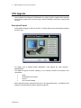
CPU Upgrade....................................................................................................................................................................... 41
Description/Tutorial......................................................................................................................................................... 41
6802982C81-C
8
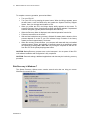
Recovery of Pre-installed Software...................................................................................................................................... 42
Disk Recovery in Windows XP ....................................................................................................................................... 42
Disk Recovery in Windows 7 .......................................................................................................................................... 43
Hard Drive Replacement ................................................................................................................................................ 44
Getting Assistance ............................................................................................................................................................... 45
Appendix A:
Safety Instructions ......................................................................................................................... 46
Appendix B:
Warranty Information ..................................................................................................................... 47
Appendix C:
CPU Specifications ........................................................................................................................ 50
Appendix B:
BIOS Factory Settings ................................................................................................................... 54
Appendix E:
Troubleshooting Information .......................................................................................................... 55
Appendix F:
Acronyms and Abbreviations ......................................................................................................... 56
6802982C81-C
9
MW810 Release R1.2 CPU Owner’s Manual
Using That Manual
Before using that manual and products it describes, be sure to read the Safety instructions in
Appendix A and the Warranty information in Appendix B.
Who Should Use that Manual
That manual is intended for staff who operate the MW810 R1.2 Mobile Workstation (herein
MW810) and need to configure, upgrade or maintain its Central Processor Unit box, which is
also referred to as either device or CPU in that manual. That manual assumes the reader is
familiar with the MW810 and basic Windows operations. If this is not the case, be sure to
read the MW810 User’s Guide and documentation that came with your version of Windows.
For documentation of supplied software applications, refer to the help file attached to each
application.
Introduction to Manual
The manual is organized as follows:
•
•
•
•
•
•
•
•
•
•
•
Getting Started
Taking a Look at the CPU
Connections
Optional Internal Peripherals
CPU Configuration
Security & Password Protection
Basic Operations
CPU Software & Firmware
CPU Upgrade
Recovery of Pre-installed SW
Getting Assistance
- an overview
- a brief functional description
- explanation of CPU connections
- a brief description of optional internal devices
- CPU configuration upon turning on
- security and protection tips
- basic operations
- CPU software and firmware
- upgrade of software and firmware components
- recovery techniques
- getting assistance from Motorola
The Appendixes contain:
•
•
•
•
•
•
Appendix A
Appendix B
Appendix C
Appendix D
Appendix E
Appendix F
- safety instructions
- warranty information
- CPU specifications
- BIOS factory settings
- troubleshooting information
- acronyms and abbreviations
Related Manuals
That manual describes the MW810 CPU and provides basic operating instructions. Please
note that although that manual refers to hardware and software components supplied with
this product, it does not provide full component description. For additional information refer
to the following documents:
•
•
•
Motorola MW810 Mobile Workstation, Installation Manual
Motorola MW810 Mobile Workstation, Service Manual
Motorola MW810 Mobile Workstation, User’s Guide
6802982C81-C
- 6802982C80
- 6802982C70
- 6802981C80
10
•
•
Motorola MW810 Mobile Workstation, Display Owner’s Guide - 6802982C85
Motorola MW810 Mobile Workstation, Software Development Kit - 6802983C00
For documentation of software applications supplied with this product, refers to the help file
attached to each application. That manual is designed to supplement the on-line help or online context-sensitive help installed with every software component. Please review this
information to ensure proper use of the product.
If you need to change the configuration of your device, refer to
•
Motorola MW810 Mobile Workstation,
Maintenance Programming Software, User’s Manual
- 6802982C95
Also, if you need to upgrade software and firmware supporting the CPU's functionality, refer
to
•
Motorola MW810 Mobile Workstation, Field Support Kit, User’s Manual - 6802982C90
For additional information visit the MW810 home page http://www.motorola.com/mw810.
Conventions Used in That Manual
Throughout this publication, you will notice the use of danger and caution marks. These
notations are used to emphasize that safety hazards exist, and care must be taken. Do not
proceed beyond a DANGER or CAUTION until the indicated conditions are fully understood
and met.
The following conventions are used throughout that manual:
Italics
Used for emphasis and for new terms.
CAPITAL LETTERS
Used to designate configuration parameters and options.
Bold
Program
Used to indicate keyboard keys or application buttons.
Motorola
CPU Manager
MW810 CPU
Used to designate the location and name of a menu function. For
example, Program Motorola MW810 CPU CPU Manager
launch CPU Manager program.
NOTE:
Indicates an operational procedure, practice, or condition to which
you should pay special attention.
CAUTION:
Alerts you of conditions, which can result in loss or corruption of data,
or damage to device.
DANGER:
Indicates a potentially hazardous situation, which, if not avoided, may
result in injury. It may also be used to alert against unsafe practices
and property-damage-only accident hazards.
6802982C81-C
11
MW810 Release R1.2 CPU Owner’s Manual
Getting Started
The Motorola MW810 Mobile Workstation (MW810) is a high-performance computing
platform, optimized to deliver seamless mobility at highway speeds. Motorola’s three-piece
design allows flexible installation options, including choice and location of CPU configuration,
display, and backlit keyboards.
•
Ruggedness
Operates with confidence in mobile environments and under stressful conditions.
•
Fixed-Mount System for Vehicles
Provides mobile connectivity and computing power for vehicle users. Internal GPS
module options work with your applications to provide accurate vehicle location so
you can manage your fleet and deploy resources more effectively.
•
Versatile Three-Piece Design
Allows for flexibility and ease of installation in space-limited vehicles. Individual
components can be purchased separately.
•
High Performance Displays
Transmissive, high contrast display performs extremely well even in difficult lighting
conditions. Display design enables shortcuts to the most important user functions.
•
Optimized for Wireless.
Expanded wireless networking capabilities, including new internal cellular modem
options, for better access to information.
The Motorola MW810 offers a range of integrated radios and GPS options so the vehicle
user can stay connected via one or more wireless networks. Optional expansion boards
provide a wide range of I/O ports to support external radios, dual displays, and peripheral
devices. The backlit keyboard and display options offer outstanding performance even in the
most difficult lighting conditions.
What is the CPU?
The CPU is a high-performance computing platform for mission-critical applications with
numerous computing, data storage, and communication capabilities. It is designed to be
permanently mounted and serve at the center of a vehicle’s computing and communications
architecture. Key features of the CPU are:
•
Windows 7 Professional Edition operating system
•
32- and 64-bit systems
•
Microsoft Windows 7 Logo Certified
•
Downgrade to Windows XP Professional operating system.
•
The Intel Core 2 Duo processor
•
Extendable system memory – 2 slots for DDR3 modules
•
Removable hard or solid state disk drive
•
A wide range of internal and external interfaces such as USB 2.0, Ethernet, RS-232,
audio, analog video, PC Card
•
Intel Wi-Fi Link 5300 network adapter.
•
Optional network cards offering complete wireless data solutions based on
Qualcomm’s Gobi2000
6802982C81-C
12
•
Optional built-in GPS receivers: with and without dead reckoning intelligence
•
High definition audio
•
Compliance with requirements for the TPM 1.2 specification
•
Vehicle ignition sense
•
Programmable general purpose inputs/outputs
•
Simultaneous operation of two independent users, each using separate display and
keyboard
•
Custom-designed cables for connection to the MW810 display or to any standard
CRT or LCD screen display (DVI and RGB interfaces)
•
Rugged mechanical design
Getting the CPU Running
This section guides you through procedures to get the CPU ready for operation.
Unpacking
Unpack your shipment and check the contents to ensure that you have received all the
specified items.
If your CPU is a part of the MW810 Mobile Workstation, refer to the Motorola MW810 Mobile
Workstation User’s Guide for a list of shipped items. If your CPU is shipped as stand-alone
device, after unpacking the shipping carton, the following items should be found:
•
•
•
•
•
CPU
Power cord
CPU-to-Display cable
Operating System recovery DVD
Field Support Kit CD with this Owner’s Guide
The MW810 Field Support Kit CD is included in the delivery scope. You will find further
information on the system, drivers, utilities, updates, manuals, etc. on this CD.
Inspect all the items. If any item is missing or damaged, notify your Motorola Customer
Service representative immediately.
NOTE: Save the packing carton and anti-static plastic bag for storage and shipping. Both the
shipping carton and the anti-static bags protect the display components from physical and
electrostatic damage.
NOTE: Motorola may stop shipping MW810 Field Support Kit CD at any time and without
notice. Instead of, Motorola will provide online access to the MW810 Field Support Kit CD
content on the MW810 support web site.
Installation and Connecting to Car Battery
Please refer to the Motorola MW810 Mobile Workstation Installation Manual and strictly
follow the installation procedure. Be aware that your device can be damaged if improperly
installed.
6802982C81-C
13
MW810 Release R1.2 CPU Owner’s Manual
Turning On the CPU for the First Time
Turn on the main power switch at the rear CPU panel and then press the power button. Your
operating system is pre-installed on the hard disk or compact flash device - it will start the
initial boot process.
CAUTION: When you turn the CPU on for the first time, the supplied software is installed
and configured. You will be presented with a mini Setup Wizard during the initial boot
process. This enables you to input the system's unique information, such a new computer
name, administrator information and serial number. This process must not be interrupted –
do not power off the CPU and follow the on-screen instructions until software installation and
configuration is fully completed.
See below (in the CPU Configuration chapter) a variety of parameters that define
functionality of the display when you turn it on. Modify configuration parameters if required.
NOTE: prior to use that manual, be sure your CPU relates to the MW810 R1.2 release.
Open the System Properties tab (right click on My Computer Æ Properties Æ General)
and verify a type of processor. The CPU box is belonging to the MW810 R1.2 release if
processor’s type is one of the following options:
•
Intel® Core™2 Duo T9400, 2.53 GHz, or
•
Intel® Core™2 Duo P8400, 2.26 GHz, or
•
Intel® Celeron® M575
6802982C81-C
14
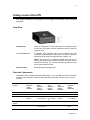
Taking a Look at the CPU
This chapter identifies the components of the display and provides a brief functional
description.
Front View
POWER BUTTON
Turns the CPU power on and off. Be aware, a main power switch
on the rear CPU panel must be switched on before using the
POWER BUTTON.
PC and SIM CARD SLOT
A Personal Card (PCMCIA type II) slot enhances the CPU
usefulness by accepting the connection of a variety of personal
cards that can be used as storage devices, modems, etc.
NOTE: The card slot is completely sealed when the door is
closed. Please select cards sized to fit within the closed door to
ensure IP54 sealing. The covered channel is provided to allow
exit by flexible antenna wires.
HARD DISK DRIVE
Removable mass storage device.
Rear-side Components
The MW810 offers multiple expansion board options, so you can add more ports for external
modems, video cameras, or other vehicle peripherals as needed. Choose one (or none) as
required.
I/O Expansion Board
Options
CPU w/o
Expansion
(Option
VA00383)
CPU with
Router
Expansion
CPU with
Serial
Expansion
CPU with
Serial
Expansion
(Option
VA00385)
(Option
VA00673)
(Option
VA00384)
CPU with ALPR
Expansion
(Option
V00497AA)
RS232
1
2
2
4
1
USB 2.0
2
3
3
3
3
Ethernet LAN RJ45
1GbE (1000
BASE-T)
1GbE + 2 100
(10/100 BASE-T)
1GbE + 2 100
(10/100 BASET)
1GbE (1000
BASE-T)
2GbE + 1 100
(10/100 BASE-T)
Secondary DVI
display
No
Yes
Yes
No
Yes
Video Input
No
1 standard
composite video
No
No
4 ALPR camera
inputs
6802982C81-C
15
MW810 Release R1.2 CPU Owner’s Manual
input port (PAL
or NTSC)
NOTE: the above table shows expansion boards available at the MW810 launch; rear-panel
configuration depends on optional expansion module included in your CPU.
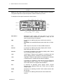
A description of rear-panel connectors is shown below:
MAIN SWITCH
Maintenance power switch. Use this switch to turn off the
workstation during maintenance operations. In daily use, the
switch should be kept in ON position.
PWR
A connector for attaching the power cord from the vehicle’s
battery
CAUTION: Use a standard Motorola power cable with a 15-Amp
fuse.
USB
USB 2.0 port for connection of external USB accessories.
DISPLAY1
A connector for attaching the primary display cable. Carries
RGB, USB and audio to the screen.
DISPLAY2
A connector for attaching the secondary display cable. Carries
DVI-D, USB and audio to the screen.
LAN1
10/100 Base-T Ethernet LAN module for connecting the LAN
cable or Ethernet device. Includes Link and Active indicators.
LAN2
1000 Base-T Ethernet LAN module for connecting the LAN cable
or Ethernet device. Includes Link and Active indicators.
SERIAL
A connector for attaching a serial device such as Motorola’s
VRM modems, printer, mouse, etc. The connection requires a
COTS cable which is not supplied with the MW810.
AUX
A connector for attaching vehicle ignition switch, General
Purpose I/O's, additional USB port, 5VDC and car battery
voltage outputs.
WWAN
Connectors for attaching mini-UHF radio modem antenna with
RX diversity.
GPS
A connector for attaching GPS antenna to the internal GPS
receiver.
6802982C81-C
16
WLAN
Connectors for attaching RF antenna (SMA) to the internal
WLAN radio with RX diversity.
AUDIO IN
External Mono microphone jack for sound input and recording.
AUDIO OUT
For connecting headphones, external speakers with power
amplifier or audio recording device.
VIDEO IN
Composite Video input for connecting external VCR or video
camera.
6802982C81-C
17
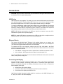
MW810 Release R1.2 CPU Owner’s Manual
Connections
CAUTION: Do not connect or disconnect any external device during the BIOS boot process
or when the CPU is in power-saving mode.
USB Device
USB devices are hot-pluggable. This means you can connect and disconnect devices while
your operating system is running. Using USB 2.0 ports you can connect external low, high,
and full-speed USB clients. CPU USB 2.0 ports support transfer rates up to 480 MB/s.
To connect a USB device, simply plug the device cable to one of the USB ports. The devices
you connect to the USB ports usually do not require installing a driver, as the required
software is already included in the operating system. However, if the USB device requires its
own software, please install it from the data carrier provided with the device.
NOTE: USB devices connected to the USB port should not consume more than 0.5A.
Otherwise the system will not operate properly.
NOTE: Be aware USB devices connected to the USB port should be compliant with the
operating system. Otherwise the system will not operate properly.
Ethernet Device
The internal 10/100/1000 Base-T Ethernet LAN modules allows you to connect your
computer to a network. The LAN1 connections support data transfer rate up to 100 Mbps; the
LAN2 connection supports data transfer rate up to 1000 Mbps.
To connect the CPU to the network, connect one end of the LAN cable to the RJ-45
connector on the CPU and the other end to the network hub. When the device is connected,
the RJ-45 indicates as follows:
•
•
Link Indicator - steady green when the system has an available connection to LAN
Active Indicator - blinks green when the system is accessing the LAN
You can use Ethernet connections for communication with Ethernet devices such as network
cards, access points, storage, etc.
Connecting the Display
The CPU graphics controller supports resolutions up to 1280 x 1024 and the simultaneous
operation of two monitors, the analog RGB (DISPLAY1 connection) and digital DVI-D
(DISPLAY2 connection). Execute the following instructions when you need to connect the
external display to the CPU:
•
Switch off the CPU and the display
•
Connect the data cable of the display to the CPU’s monitor connection
•
First switch on the display and then the CPU
Use Motorola original integrated molded cables for connection to the MW810 display or to
3rd-party LCD, CRT or Flat Screen displays.
6802982C81-C
18
When two monitors are connected, the CPU graphics software provides the following
graphics options:
•
Extended desktop
Extended desktop is a feature in a computer that allows a user to extend viewing
capabilities by using two or more monitors at the same time. Extended desktop mode
allows the user to display a single document or application across multiple monitors, or
use each monitor to display a different document or application. It also allows the
monitors to have independent resolutions, color depth, and refresh rates.
•
Clone Display
Clone display is a display configuration in which two displays can each have an
independent set of timings. Clone is beneficial when using displays that support various
resolutions and refresh rates.
•
Dual Display Twin
Twin display is a display configuration in which two displays are driven by the same set
of timings. Both display devices should support those timings (resolution, refresh, etc).
NOTE: Graphic controller supports resolutions up to 1280x1024. If you use MW810 display,
XGA resolution (1024 x 768) is recommended.
Storage Device
Your CPU is equipped with a removable hard or solid state disk drive. 2.5-inch hard disk
drive with SATA interface, three-dimensional shock absorber and integrated control circuitry
provides the most rugged solution for hard disk drives. The HD system comes with a built-in
heater that automatically turns on at low temperature.
CAUTION: If the operating system is running from the HD or SSD, never try to remove or
install the hard disk drive while the computer is powered on. Doing so can result in loss of
data, and can damage the computer and the hard disk drive’s sensitive circuitry.
External Audio Device
The audio subsystem includes digital audio and analog mixing functions required for
recording and playing sound on your computer. Microsoft Windows Sound System supports
internal microphone and capability to connect external audio devices.
NOTE: Motorola integrated molded cable for connecting to the MW810 display also
incorporate the audio output to the display's loudspeaker.
Serial Device
The CPU has serial ports for connecting a variety of serial devices. The devices you connect
to the Serial ports usually do not require installing a driver, as the required software is
already included in the operating system. However, if the serial device requires its own
software, please install it from the data carrier provided with the device.
6802982C81-C
19
MW810 Release R1.2 CPU Owner’s Manual
Follow instructions below when you need to connect a serial device to the CPU:
•
•
•
•
•
Switch the CPU off
Connect the data cable of the serial device to the serial interface on the CPU
Plug the serial device power cable into the grounded main outlet
First switch the device on, then the CPU
Install a driver (if required)
Video Input
The CPU has an analog video input port on the rear CPU panel for connecting a video
capture device. To connect a video capture device, simply plug the device cable to the VIDEO
IN input port.
Auxiliary Port
The AUX port provides four digital bits GPIO that may be configured either for input or
output. The GPIO DIRECTION parameter in the CPU's codeplug defines a direction of specific
GPIO line, the GPIO LEVEL codeplug parameter allows selecting the voltage level for specific
GPO – 5VDC or car battery voltage is available options. In addition, you can define initial
GPO state after power up via the GPIO STATE codeplug parameter.
NOTE: When a port is configured for input, the external voltage must be supplied to that port
via 160 Ohm resistor to ensure proper operation.
CAUTION: When a port is configured for output, be aware not supply external voltage to that
port may – it may damage the device.
The auxiliary port provides ignition sense connection to the MW810. See the MW810
installation manual for details.
This port can also be used to supply 5VDC 1A max and vehicle battery voltage out 1A max
to external devices connected to the MW810 CPU.
6802982C81-C
20
Optional Internal Peripherals
CAUTION: You can upgrade your CPU by addition of internal networks cards, installing CF
card or changing system memory. However, to avoid damage during the installation
procedure, please ask authorized personnel for help. Refer to the MW810 Service Manual
for description of the CPU internal modules and field-upgradeable components.
Wireless LAN
Depending on your model, the Intel Wi-Fi Link 5300 network adapter may be integrated in
your CPU. This card is an embedded 802.11a/b/g/n PCI-e Mini Card network adapter
operating in the 2.4GHz and 5GHz spectrum. The network adapter supports the latest
wireless industry standards and can easily be connected to existing Ethernet networks. This
means you can use the WLAN network adapter just as with a cable-connected Ethernet.
The Intel Wi-Fi Link 5300 network adapter operates in accordance with the IEEE 802.11
standard.
Key Features
•
•
•
•
•
•
•
Dual-Band, Quad-Mode solution (802.11a/b/g/n) in the 2.4GHz and 5GHz spectrum
Up to 450 Mbps of Bandwidth; in addition to enabling multiple applications to
simultaneously access the network resulting in increased productivity
Multiple Input Multiple Output (MIMO) Technology
Support for antenna diversity to enable optimized WLAN performance for multiantenna systems
Industry-standard wireless LAN security support (802.1x, WEP 128- and 64-bit,
WPA, WPA2, AES-CCMP 128 bit, LEAP, PEAP, TKIP)
Compatible with Intel My WiFi Technology
Compatible with Intel® PROSet WLAN management software
For additional information about the network adapter modem refer to Intel Wi-Fi Link 5300
network adapter manual.
Installation
Generally, the drivers and the tools are already preinstalled. If the drivers and the tools have
not yet been installed, you can find the install package in the C:\Drivers\WLAN folder of the
original MW810 operating system image or reinstall the WLAN software by using the MW810
Field Support Kit CD-ROM.
If it should be necessary to reinstall the WLAN software, refer to the MW810 Field Support
Kit User’s Manual for details.
NOTE: You may require administrator privileges to install software. Make sure you have the
necessary rights.
Settings
Network adapter states upon turning on the CPU can be defined either in the CPU codeplug
or the CPU registry.
6802982C81-C
21
MW810 Release R1.2 CPU Owner’s Manual
•
The WLAN parameter of the CPU codeplug specifies a state of WLAN network
adapter after the CPU is turned on. Factory codeplug setting of the WLAN network
adapter is ON.
•
The MW810 Manager application allows selecting the state of the WLAN network
adapter after operating system start. Factory registry setting of the WLAN network
adapter is ON.
If the WLAN software is installed and the network adapter is powered on, the "Wireless LAN"
radio icon appears in the lower right-hand corner on the toolbar of your Windows desktop
(for Windows XP only). The background color of the 'wave' icon indicates the connection
status. The following color code displays connection status:
•
•
•
•
•
White: adapter searches for available wireless network: very poor connection quality
or no connection
Yellow: an available wireless network is found
Green: adapter is connected to a wireless network. Green waves indicate
connection status: the more waves mean the better quality of received signal.
Red: There are no available wireless networks found. Intel PROSet/Wireless
periodically scans for available networks
Crossed out: adapter is off and does neither transmit nor receive
You can display the connection status by positioning the mouse pointer on the icon.
Wireless WAN
Depending on your model, your CPU may include an integrated WWAN solution based on
Qualcomm’s Gobi2000. That solution supports major RF bands around the world - all with
one chipset. Gobi2000 solution makes it possible to procure and support one wireless device
that works on multiple wireless networks. A list of supported wireless networks is shown
next:
•
EV-DO/EV-DO Rev. A 800MHz
•
EV-DO/EV-DO Rev. A 1900 MHz
•
HSDPA/HSUPA 800MHz
•
HSDPA/HSUPA 850MHz
•
HSDPA/HSUPA 900MHz
•
HSDPA/HSUPA 1900MHz
•
HSDPA/HSUPA 2100MHz
•
GSM/GPRS/EDGE 850MHz
•
GSM/GPRS/EDGE 900MHz
•
GSM/GPRS/EDGE 1800MHz
•
GSM/GPRS/EDGE 1900MHz
6802982C81-C
22
Key Features
•
•
•
•
•
•
•
•
Support third generation (3G) digital cellular standards
Technology/Bands
o HSPA/UMTS – 800/850/900/1900/2100 MHz
o Quad-band EDGE/GPRS/GSM – 850/900/1800/1900 MHz
o Dual-band EV-DO/CDMA –800/1900 MHz
Receive Diversity on all HSPA/UMTS/EV-DO/CDMA bands
Data Speeds
o HSDPA/HSUPA DL/UL – 7.2 Mbps/5.76 Mbps
o WCDMA DL/UL – 384 kbps/384 kbps
o GSM DL/UL – 14.4 kbps/14.4 kbps
o GPRS DL/UL – 85.6 kbps/42.8 kbps
o EDGE DL/UL – 236.8 kbps/118.4 kbps
o EV-DO FL/RL – 3.1 Mbps/1.8 Mbps
o CDMA 1xRTT FL/RL – 153 kbps/153 kbps
WHQL-certified USB software driver architecture
AT command interface
Card vendor supplied SDK including Application Program Interface
Standalone carrier certification
Installation
Generally, the drivers and the configuration utility are already preinstalled. If the drivers and
the tools have not yet been installed, you can find the install package in the C:\Drivers
\Sierra folder of the original MW810 operating system image or reinstall the CDMA software
by using of the MW810 Field Support Kit CD.
If it should be necessary to reinstall the CDMA software, refer to the MW810 Field Support
Kit User’s Manual for details.
NOTE: You may require administrator privileges to install software. Make sure you have the
necessary rights.
CAUTION: If you use an integrated WWAN radio, switching over to the Standby mode is not
recommended as this may lead to an interruption in the network connection.
NOTE: For connection to the networks, you need establish a subscription with a service
provider. Check with your service provider for a list of available wireless data services.
GPS Receiver
Optional GPS receiver may be integrated in your CPU. MW810 offers 2 GPS options:
Trimble Lassen iQ module or u-blox SBR-LS module with the dead reckoning intelligence.
Trimble's Lassen iQ Module
Trimble's Lassen iQ module is 12-channel GPS module with ultra-low power consumption.
The module features two GPS signal sensitivity modes: Standard and Enhanced. With
Enhanced mode enabled, the module automatically switches to higher sensitivity when
satellite signals are weak.
The Lassen iQ module operates using one of three protocols - TSIP, TAIP, or NMEA 0183.
6802982C81-C
23
MW810 Release R1.2 CPU Owner’s Manual
•
TSIP is a powerful binary packet protocol that allows maximum configuration control
over the GPS receiver for optimum performance in any number of applications.
•
TAIP is the Trimble ASCII interface protocol designed specifically for vehicle tracking
applications. It is a bi-directional protocol using simple ASCII commands with the
associated ASCII responses.
•
NMEA 0183 is an industry standard protocol common to marine applications. NMEA
provides direct compatibility with other NMEA-capable devices such as chart
plotters, radars, etc. The Lassen iQ GPS module most NMEA messages for GPS
navigation. NMEA messages and output rates can be user selected as required.
Key Features
•
•
•
•
•
•
12-channel simultaneous operation
NMEA 0183, TSIP, TAIP protocols
Dual sensitivity modes with automatic switching
Aided GPS through TSIP
Antenna open and short circuit detection and protection
Two serial ports
Configuration
The Lassen iQ GPS receiver has two serial ports and can be configured for RTCM SC-104
input which is the GPS industry standard for differential correction data. The receive side of
the port 2 is factory configured to accept RTCM data.
The factory default settings are:
•
•
Port 1, TSIP bi-directional
Port 2, NMEA 0183 OUT / RTCM SC-104 V2.1 IN
Trimble provides the iQ_Monitor and the GPSSK interface programs to monitor GPS
performance and to assist system integrators in developing a software interface for the GPS
module. Contact Trimble for further information.
Dead Reckoning Module
The Sensor-Based GPS Receiver containing the ANTARIS® GPS positioning engine
provides accurate positioning in areas where GPS reception is blocked, for example in
tunnels, city canyons, indoor and underground parking facilities, and as well as other difficult
areas. Sensor-based GPS receiver supplements the GPS information with an incoming
signal from a gyroscope and from odometer pulses to reconstruct the traveled route through
long periods of GPS outages with aid of dead reckoning algorithms.
Key Features
•
•
•
•
•
•
•
•
6802982C81-C
16-channel GPS receiver
Dead reckoning (DR) with enhanced Kalman filter
Mixed GPS and DR operation, depending on availability and quality of GPS signal
Fully automatic calibration
Temperature compensation
Based on the ANTARIS GPS technology
Differential GPS (DGPS) support
Active antenna support
24
•
Active antenna supervisor for short and open circuit detection
The u-center GPS Evaluation Software provides a powerful tool for evaluation, performance
analysis and configuration of u-blox GPS receivers. That software is not a part of the MW810
software installation, contact u-blox for further information.
Configuration
The dead reckoning module has two serial ports which support NMEA, UBX Binary, and
RTCM protocols. The factory default settings are:
•
•
Port 1, NMEA 0183
Port 2, UBX Binary
Settings
The GPS receiver state upon turning on the CPU can be defined either in the CPU codeplug
or the CPU registry.
•
The GPS parameter of the CPU codeplug specifies a state of GPS receiver after the
CPU is turned on. Factory codeplug setting of the GPS receiver is OFF.
•
The MW810 Manager application allows selecting the state of the GPS receiver after
operating system start. Factory registry setting of the GPS receiver is OFF.
•
The GPS PORT parameter of the CPU codeplug selects a port in the GPS receiver
which user application is connected to. Factory codeplug setting of the GPS port is
PORT1.
•
The MW810 Manager application allows selecting of the GPS port after operating
system start. Factory registry setting of the GPS Port is PORT1.
NOTE: dead reckoning intelligence can be achieved only if vehicle speed (SPEED+ and
SPEED-) and direction (FWD+, FWD-) inputs are connected to the CPU auxiliary port. See
the MW810 installation manual for details.
System Memory
The CPU has two internal slots for DDR3 memory modules. You can upgrade system
memory up to 4GB as follows:
•
•
•
•
1GB PC2-5300/667MHz in one DDR3 slot
2GB PC2-5300/667MHz in one DDR3 slot
2GB PC2-5300/667MHz in two DDR3 slots (1GB each)
4GB PC2-5300/667MHz in two DDR3 slots (2GB each)
6802982C81-C
25
MW810 Release R1.2 CPU Owner’s Manual
CPU Configuration
The CPU stores its configuration in the codeplug and the BIOS flash. This section describes
various configuration parameters that can be selected and modified if required.
CPU Codeplug
The CPU codeplug is a protected memory area to store the configuration parameters
accessed when you turn on the device. That binary-format data contains basic information
about CPU capabilities including power-up, power-off modes, a status of peripheral devices,
etc.
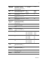
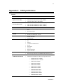
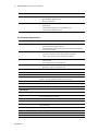
Codeplug Configuration Parameters
PARAMETER
DESCRIPTION
AVAILABLE OPTIONS
FACTORY
SETTING
POWER
SOURCE
Specifies a kind of car battery the CPU
is connected to.
9V, 12V, or 24V
12V
IGNITION BOOT
PREFERENCES
Selects desired CPU reaction when
the ignition switch is turned on.
NONE – Ignore turning the
ignition switch on.
POWER ON
POWER ON - Turn on if
CPU is off; ignore if CPU is
already on
WAKEUP – Wake up CPU
from standby mode; ignore
if CPU is already active
MIXED – Wake up if CPU
is in standby mode; Turn
on if CPU is off
POWER BUTTON LOCK –
Block the power button
until you turn on the ignition
switch
POWER BUTTON
PREFERENCES
Selects desired method to turn the
CPU off.
CPU POWER BUTTON Turn on/off when pressure
of the CPU power button.
DISPLAY1 POWER
BUTTON - Turn on/off
when the primary display is
turned off.
IGNITION SHUT
DOWN
PREFERENCES
Selects desired CPU reaction when
the ignition switch is turned off.
ENABLE
DISPLAY2 POWER
BUTTON - Turn on/off
when the secondary
display is turned off.
ENABLE
SHUTDOWN WHILE
IGNITION ON - Specifies
whether computer takes an
action when press the
Power button while the
Ignition switch is turned on.
DISABLE
NONE – Ignore turning the
ignition switch off.
SHUTDOWN
SHUTDOWN - Turn off the
CPU.
STANDBY – Force standby
mode.
6802982C81-C
ENABLE
26
IGNITION SHUT
DOWN TIMER
When IGNITION SHUT DOWN
PREFERENCES = SHUTDOWN,
selects the amount of time to elapse
between turning the ignition switch off
and CPU shutting down.
0 … 127 seconds or
CRITICAL TURN
OFF
Enables or disables turning the device
off by pressing and holding the power
button for 6 seconds or more.
CPU
ENABLE
DISPLAY1
ENABLE
DISPLAY2
ENABLE
WLAN
Specifies the state of the WLAN radio
after CPU power up.
ON / OFF
ON
WWAN
Specifies the state of the WWAN radio
(UMTS/CDMA/DataTAC) after CPU
power up.
ON / OFF
ON
GPS
Specifies the state of the GPS receiver
after CPU power up.
ON / OFF
OFF
HD
MAINTENANCE
Specifies a time of HD maintenance
(keeping the HD temperature within
the operating range for a certain
period of time set by this parameter)
while the CPU is off.
0 … 16 hours
12 hours
1W SUPPORT
Specifies whether the CPU support 1wire interface with the display.
ENABLE / DISABLE
ENABLE
GPS PORT
Selects an input port of the GPS
receiver.
PORT1 / PORT2
PORT1
WAKE-UP from
INTERNAL
WWAN RADIO
Enables or disables wake-up from the
RI line of the serial COM3 port
connected to internal PRM240 radio
modem.
ENABLE / DISABLE
ENABLE
GPIO DIRECTION
Defines a direction of specific GPIO
line.
GPIO1 – INPUT/OUTPUT
OUTPUT
GPIO2 – INPUT/OUTPUT
OUTPUT
GPIO3 – INPUT/OUTPUT
OUTPUT
GPIO4 – INPUT/OUTPUT
OUTPUT
GPO1 – ON/OFF
OFF
GPO2 – ON/OFF
OFF
GPO3 – ON/OFF
OFF
GPO4 – ON/OFF
OFF
GPO1 – 5V/CAR BATT
5V
GPO2 – 5V/CAR BATT
5V
GPO3 – 5V/CAR BATT
5V
TIME-OUT
GPIO STATE
GPIO LEVEL
Defines initial GPO state after power
up.
Defines the voltage level for specific
GPO.
3 minutes
0 … 127 minutes
GPO4 – 5V/CAR BATT
5V
CAR BATTERY
OUTPUT
Enables or disables the car battery
voltage output at the auxiliary
connector when the CPU is powered
on.
ENABLE / DISABLE
ENABLE
CAR BATTERY
CONTROL
Enables or disables the car battery
voltage output at the auxiliary
connector when the CPU is powered
off.
ENABLE / DISABLE
DISABLE
5V OUTPUT
Enables or disables the 5VDC output
at the auxiliary connector.
ENABLE / DISABLE
ENABLE
RELIABILITY
MONITOR
Enables or disables monitoring of CPU
reliability information.
ENABLE / DISABLE
ENABLE
6802982C81-C
27
MW810 Release R1.2 CPU Owner’s Manual
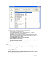
CPU Configuration Change
This section describes the software configuration tool and the most common method to
change the CPU configuration parameters.
Maintenance Programming Software
The Maintenance Programming Software allows modifying display configuration that starts
when you turn the display on. Use the MPS context-sensitive on-line help information for
assistance in configuring the device.
How to Modify Configuration Parameters
To modify the configuration parameters perform the following:
•
Double-click on the MPS icon; main MPS window appears on the screen.
•
Click on the Codeplug Editor icon
6802982C81-C
28
To modify configuration parameters use the MPS tool as shown next:
•
•
Choice the CPU in the Select Device field
Click on Read from device to read the codeplug parameters. If your device is
successfully read, you will see a list of parameters.
CAUTION: Incorrect configuration can make the device unworkable. Please, make
sure to acquire the appropriate codeplug. Always make a backup copy in case you
have made a mistake during the update.
•
Click on Save to File to backup the original codeplug data.
•
Modify a parameter per your selection.
•
Click on Write to device to program the device and wait for a confirmation of
successful programming completion.
NOTE: For details refer to Maintenance Programming Software User’s Manual.
BIOS Setup
The BIOS is a program stored on a Flash chip on the motherboard initializing the CPU prior
to the start of the operating system. The BIOS parameters define the CPU system functions
and the hardware configuration.
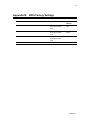
Settings in BIOS Setup
When you restart the CPU, the M-logo display briefly appears on the screen. To enter the
BIOS Setup, press the DEL key when this display appears. If a password has been assigned,
type the password and press the Enter key.
6802982C81-C
29
MW810 Release R1.2 CPU Owner’s Manual
The BIOS Setup Utility that enables the selection and modification of different BIOS setup
parameters and contains the menus as shown next:
•
•
•
•
•
Main: for system information and time/date settings
Boot: for configuring the boot sequence
Security: for password and TCG settings functions
Recovery: for system recovery settings
Exit: to save and exit the BIOS Setup
NOTE: If you have forgotten the password, contact your system administrator.
Operating BIOS Setup
Available BIOS menus are shown at the top of the BIOS window. Use the
keys to navigate between menu items.
and
arrow
Available menu parameters are shown in the left-hand window of the BIOS. The description
of the individual settings is shown in the upper right-hand window of the BIOS. The
description of the navigation through the BIOS and selecting the menu or parameter you
wish to access to make changes is shown in the bottom right-hand window.
If you need to display help on the operation of BIOS Setup - press the F1 key.
CAUTION: Refer to the Appendix D for factory setting of the BIOS parameters. You can
change these settings which will take effect as soon as you save and quit the BIOS Setup.
Be aware, incorrect BIOS configuration can make the device unworkable.
Boot from USB Mass Storage Device
Boot priorities in the BIOS setup appear as groups, there are groups of Hard Drives and
Floppy Drives. The BIOS classifies USB mass storage device according to its size as
follows:
•
•
“Floppy Drive” is storage capacity is less than 512 MB
“Hard Drive” if storage capacity is more than 512 MB
Configure the BIOS to support MW810 boot-up from a USB mass storage device as follows:
•
•
•
•
•
Enter to BIOS menu and go to “Boot” screen
If size of USB mass storage is less than 512 MB, go to “Boot Option #1”
If size of USB mass storage is more than 512 MB, go to “Boot Options #5” and
enter “Hard Drive BBS Priorities” option
Select USB mass storage device to be the first boot option.
Save changes and exit BIOS setup.
Put attention, if you remove USB device which is classified as “Hard Drive”, then BIOS
automatically will set boot priority to internal hard drive. Next time, when you plug-in USB
device, you will have to set the boot priorities again.
Exiting BIOS Setup
To exit BIOS Setup, select the Exit menu from the menu bar. You can then decide which
settings you want to save. The Exit menu offers the following options:
6802982C81-C
30
•
•
•
•
Save Changes and Exit - Exit the BIOS setup after saving the changes
Discard Changes and Exit - Exit the BIOS setup without saving of any the change
Save Changes - Save changes done so far to any of setup options
Discard Changes - Discard changes done so far to any of setup options
Mark the required option and activate it with the Enter key.
6802982C81-C
31
MW810 Release R1.2 CPU Owner’s Manual
Security and Password Protection
Trusted Platform Module
The CPU firmware meets compliance requirements for the Trusted Platform Module (TPM)
1.2 specification. TPM 1.2 is an essential level of compliance for secure start of Windows XP
or Windows 7 operating systems. When the TPM is enabled, the CPU will ensure that
unauthorized code cannot invade a device in its boot process.
To use the TPM, you must be sure to activate the TPM in the BIOS Setup. The condition for
this is that you have entered at least the administrator's password.
•
•
•
Call BIOS Setup and select the Security menu
Select the entry TRUSTED COMPUTING item and press the Enter key
Select desired TPM STATE option
TPM is functional when TPM STATE = ENABLED. Disabled TPM is not able to execute
commands that use the resources of a TPM. TPM is not able to load keys and
perform other operations. Even if a disabled TPM has a TPM Owner, it is not able to execute
normal TPM commands.
If you have activated the TPM, the menu item PENDING TPM OPERATION will schedule the TPM
operations as follows:
•
NONE
- no operation is pending
•
ENABLE TAKE OWNERSHIP
- when TPM enabled but without an owner this
command allows the ability to take ownership.
•
DISABLE TAKE OWNERSHIP
- when TPM enabled but without an owner this
command disallows the ability to take ownership
•
TPM CLEAR
- return the TPM to factory defaults
When the TPM is activated, it initially takes control of the CPU during each start-up to check
all hardware components and the BIOS Setup for trustworthiness. In the further course of
operation, the TPM checks the operating system, certain drivers and applications. If a
component does not have a valid certificate, the TPM refuses this component access to
protected content.
For example, with the TPM activated, data can be generated which can only be read or run
on this device.
Password Protection in BIOS Setup
You can prevent unauthorized opening of the BIOS Setup with both the administrator's and
the user's password.
•
If only the administrator password is set, then this only limits access to setup and is
only asked for when entering the BIOS Setup
•
If only the user's password is set, then this is a power on password and must be
entered to boot or enter the BIOS Setup. In Setup the user will have administrator
rights. Note the following before using the password protection for your data security
in the BIOS Setup:
6802982C81-C
32
Please remember your passwords in either case, as you will not be able to access your
BIOS Setup and/or your system any longer, if you forget both the user's and the
administrator's passwords. Passwords are not covered by your warranty and a charge will
be made for assistance.
Passwords can be up to eight characters long. You can use all alphanumeric characters and
need not distinguish between uppercase and lowercase characters.
Set the supervisor and user password
To assign the administrator's password do as follows:
•
•
•
•
•
•
Call the BIOS setup and select the Security menu
Mark the Administrator Password field and press the Enter key
Enter the password in the Create new Password field and press the Enter key
Confirm the new password when it is requested
Enter the password again and press the Enter key
Exit the BIOS setup after saving the changes
To assign the user's password do as follows:
•
•
•
Call BIOS setup and select the Security menu
Mark the User Password field and proceed exactly as when configuring the
supervisor password.
Exit the BIOS setup after saving the changes
Changing administrator's or user's password
•
•
•
Call the BIOS setup and select the Security menu
When changing the password, proceed exactly as for password assignment
You can only change the administrator's password when you have logged in with the
administrator rights and the user's password when you have logged in with the user
rights
Cancelling passwords
To cancel passwords proceed as follows:
•
•
•
•
•
Call the BIOS setup and select the Security menu
Mark the Administrator Password or the User Password field and press the Enter
key
With Create New Password you will then be asked to enter a password
Press the Enter key twice
Exit the BIOS setup after saving the changes
6802982C81-C
33
MW810 Release R1.2 CPU Owner’s Manual
Basic Operations
This section describes the following display operations:
•
•
•
Power On
Power Off
Power Management
NOTE: Proper CPU functionality can be achieved only if the MW810 CPU Control package
is installed. This package is a part of the MW810 CPU software image. Refer to the CPU
Software chapter in this document for details.
Power On
NOTE: Prior to powering on the CPU, ensure that the main power switch on the rear CPU
panel is in the ON position.
The CPU can be turned on either from the vehicle ignition switch or from the power button
located on the front panel.
The POWER UP PREFERENCES parameter in the CPU's codeplug provides an option to turn on
the CPU the power button:
•
POWER BUTTON
When POWER
CPU on.
- Turn on pressure of the power button on CPU or Display units.
BUTTON = ENABLE,
press the CPU or display power button – it will power the
The IGNITION BOOT PREFERENCES parameter in the CPU's codeplug provides an option to turn
on the CPU from the ignition switch:
•
•
•
NONE
POWER ON
POWER BUTTON LOCK
- Ignore the ignition switch.
- Turn on if CPU is off; ignore if CPU is already on
- Block the power button until you turn on the ignition
switch
•
WAKEUP
- wake up CPU from standby mode; ignore if CPU is
already active
When POWER ON or POWER BUTTON LOCK options are selected, insert the car key into the
ignition switch and rotate it to ACC position - it will power the CPU on.
When the CPU is turned on, the pre-installed Operating System will be automatically loaded.
This process takes some time; please wait until this process is completed before using the
computer.
CAUTION: If POWER BUTTON = DISABLE, only the ignition switch can turn the device on. Make
sure, in that case IGNITION BOOT PREFERENCE setting is POWER ON or POWER BUTTON LOCK.
CAUTION: Extreme Temperature Conditions
The device is operational only within valid temperature range. When the ambient
temperature is beyond the operational range or internal CPU temperatures are beyond the
allowed thresholds, the device will indicate about operational failure and not power on.
CAUTION: Discharged Vehicle Battery
6802982C81-C
34
The device is operational when the car battery voltage is within valid range. The device will
not power up when a level of the car battery voltage is below the Low Battery Threshold
(refer to Appendix C for absolute value of the threshold).
Power Off
The device can be turned off either from the CPU or from the power button located on the
display’s front.
The POWER OFF PREFERENCES parameter provides four options to turn off the device: DISPLAY
REQUEST, CPU POWER BUTTON, DISPLAY1 POWER BUTTON, and DISPLAY2 POWER BUTTON. You can
select any of above options or use their combination.
•
•
•
•
When CPU POWER BUTTON = ENABLE, pressure of the CPU power button will force
power off.
When DISPLAY1 POWER BUTTON = ENABLE, pressure of the power button on the
primary display will force power off.
When DISPLAY2 POWER BUTTON = ENABLE, pressure of the power button on the
secondary display will force power off.
When DISPLAY REQUEST = ENABLE, the device will automatically shut itself down when
the CPU issues power off request.
Additional option to shut the device down is turning off the ignition switch. This option will
work if setting of the IGNITION SHUT DOWN PREFERENCES parameter in the CPU's codeplug is
SHUTDOWN. When using of this option, you can select the amount of time to elapse between
turning the ignition switch off and CPU shutting down by means of the IGNITION SHUT DOWN
TIMER parameter.
If the system does not respond, you can turn the device off by pressing and holding the CPU
power button for 6 seconds or more. To permit this option, enable CRITICAL TURN OFF. Be
aware, this uncontrolled hardware power off may damage CPU hard disk.
CAUTION: Extreme Shut Down
Some extreme events such as temperature below the low or above the high operating limit
or discharged car battery might cause the device to power off.
•
Internal temperature is beyond the operational limit.
If during operation the internal temperature is close to the low or high operational
limits, the display will provide the warning temperature indication. If during operation
the internal temperature goes out of the operational limits, the display eventually
powers off.
•
Vehicle battery is discharged.
If, during normal operation, the battery voltage drops below the Low Battery
Threshold, the display will provide the low car battery indication. If the voltage
continues to drop, the device automatically powers off at the Critically Low Battery
Limit.
•
Drops in car battery voltage.
If battery voltage falls below the Battery Cranking Threshold for 20 seconds or more,
the device will execute critical shut down and power itself off.
CAUTION:
6802982C81-C
35
MW810 Release R1.2 CPU Owner’s Manual
The device automatically shuts down then the internal temperature exceeds the upper limit
of the valid range. Never turn on the device until it cools down.
Power Scheme
The CPU in combination with the operating system allows reducing of the power
consumption of your entire system. You can do this by selection of appropriate power
scheme which will define the power usage by your computer. Available options are as
follows:
•
•
•
•
Standby
On standby the CPU switches to a low-power mode where devices use less power.
When you want to use the computer again, it comes out of standby quickly, and your
desktop is restored exactly as you left it. In the standby mode the content of the
main memory is saved by continuing to supply the main memory with power, while
the processor, monitor, hard disk and other internal components are turned off.
Hibernation
Hibernate feature saves everything in memory on disk, turns off your monitor and
hard disk, and then turns off your computer. When you restart your computer, your
desktop is restored exactly as you left it. It takes longer to bring your computer out of
hibernation than out of standby.
Monitor Off
In this state the CPU automatically turns off the monitor.
Hard Disk Off
In this state the CPU automatically turns off the hard disk.
Windows Power Options (Start
Settings
Control Panel
Power Options
Power
Schemes) allows adjustment of the individual settings in a power scheme. You can specify
the period of inactivity that you want to elapse before the CPU turns off the monitor/hard
disk, or goes to Standby/Hibernate mode.
Standby
The CPU can initiate the standby manually or automatically after a period of inactivity that
you may pre-define. The period of inactivity means not making any entry on your computer
for a certain time.
Manual methods to enter Standby mode are as follows:
•
•
•
Standby selection in the Shutdown Window of the operating system
Power button pressure (if configured)
Turning the ignition switch off (if configured)
For details about the power button, refer to the help file attached to Windows Power Options
(Start Settings Control Panel Power Options Advanced). Default setting of the
operating system does not allow Standby from the power button.
Turning the ignition switch off may force the CPU standby depending on setting of the
IGNITION SHUT DOWN PREFERENCES parameter. If your intention is going to Standby when the
ignition is off, permit that feature by enabling of the STANDBY option.
When the CPU is in Standby, it suspends all USB accessories connected to it. When you
resume work, your notebook returns to the place at which you discontinued working.
6802982C81-C
36
Wake Up
The CPU wakes up on occurrence of one of events below:
•
•
•
•
•
Wake up event from an USB HID device connected to the CPU
Wake up event from an Ethernet device connected to the CPU
Ring Indicator from the RS-232 port
Power button pressure (if configured)
Ignition switch (if configured)
Wake up event from USB HID device can resume the CPU out of standby if its setting
specifies the operating system to come out of a low power state when there is USB or
Ethernet activity. To enable this feature, Allow this device to bring the computer out of
standby option (Power Management tab in Properties) should be selected. For details
about this option, refer to the help file attached to the Properties of the device.
Default setting of the operating system allows resume from USB HID or Ethernet devices.
A device connected to 10/100/1000M Ethernet port can use both 'magic' and 'direct' packets
for remote CPU wake up. To activate the remote wake up, check Wake on Directed
packet or/and Wake on Magic packet in the device properties.
Pressure of the Power button will bring the computer out of standby if its setting specifies
the operating system to come out of a low power state when you press the Power button.
For details about this option, refer to the help file attached to Power Options (Start
Settings Control Panel Power Options Advanced).
Default setting of the operating system does not allow resume from the power button.
Turning the ignition switch on may wake up the CPU depending on setting of the IGNITION
BOOT PREFERENCES parameter. If your intention is going to Standby when the ignition is off,
permit that feature by enabling of the STANBY option.
Power Management Tips
•
Typically, you turn off the monitor or hard disk for a short period to conserve power.
If you plan to be away from your computer for a while, put your computer on standby
to place entire system in a low-power state.
•
Put your computer in hibernation when you will be away from the computer for an
extended time or overnight. When you restart the computer, your CPU is restored
exactly as you left it.
•
If you use an integrated UMTS/CDMA radio, switching over to the Standby mode is
not recommended as this may lead to an interruption in the network connection.
•
Do not switch the CPU off while it is in one of the energy-saving modes. When you
are finished working - come out of a power-saving mode and then turn off as normal.
•
If the CPU is in a power-saving mode:
o Do not connect any external devices
o Do not disconnect any external devices
o Do not install or remove a PC- or Express card
o Do not add or remove RAM
6802982C81-C
37
MW810 Release R1.2 CPU Owner’s Manual
HD Heater
The CPU hard drive is equipped with the heater that allows the hard disk to work in low
temperature. The CPU automatically controls the heater and turns it on and off depending on
the temperature in the HDD compartment.
Low Temperature Conditions
The device supports working hard disk conditions even if it’s turned off. When the ambient
temperature drops below the low hard disk operational limit, an internal heater will
automatically adjust and maintain the working conditions (see Hard disk heating when
device is off parameter in the CPU configuration section) for a pre-defined time.
•
If the CPU is turned on when Hard disk heating when device is off time-out has
not expired yet and the hard disk temperature is within the operating range, the CPU
will boot up immediately.
•
If the CPU is turned on when Hard disk heating when device is off time-out has
been expired and the hard disk temperature is below the low hard disk operational
limit, the CPU will activate the internal heater and will boot up only when the hard
disk temperature returns to the operating range. The heating process takes some
time - please wait until this process is completed.
6802982C81-C
38
CPU Software & Firmware
BIOS
The BIOS is the built-in firmware that initializes basic elements of the CPU module before
operating system start and without accessing programs from a bootable storage device.
Also, the BIOS communicates with the keyboard controller (Embedded Firmware) and place
a standard interface layer between platform hardware and operating system.
The BIOS is built with the EFI technology and place a standard interface layer (ACPI)
between platform hardware and operating system.
Key Features
The BIOS provides basic services as follows:
•
•
•
•
•
•
•
•
•
•
Support 32- and 64-bit single and dual core CPU and Intel’s Montevina platform
Support OS: Windows XP, Windows 7
Vendor identification for OPK installation
WHQL-certified software architecture
Multiple boot devices: HD or SSD, USB 2.0 mass storage device, PXE boot from
Ethernet device, CD-ROM
BIOS Recovery options: USB mass storage device; BIOS recovery process provides
boot block method to recover in case of BIOS corruption
The Video BIOS into the system BIOS image
Re-flashing in DOS and in Windows
BIOS setup
TPM 1.2 support
Embedded Controller
The Embedded controller is the built-in firmware that provides basic services as follows:
•
•
•
•
•
•
•
Implement power on/off sequence
Measure internal temperatures in most critical points
Implement thermal control algorithm allowing withstanding with -30°C…+70°C
ambient temperature
Implement fan control to allow cooling internal temperature down
Control by GPIO lines
Implement internal heater control to allow heating the device up when low ambient
temperature
Support the CPU configuration parameters
Operating System
CPU operating system is Windows XP or Windows 7 image customized for the CPU
hardware. Software architecture of the CPU is WHQL-certified.
6802982C81-C
39
MW810 Release R1.2 CPU Owner’s Manual
CPU Control Package
Proper CPU functionality can be achieved only if the MW810 CPU Control package is
installed. This package is a part of the MW810 CPU software image.
The services package is a collection of Windows applications and services allowing the end
user capability to utilize the CPU features. The list of these tools is shown next:
•
MWCPUDriver
- a driver providing an access to the CPU hardware.
•
MWCPUService
•
MWCPUAgent
- service application to provide API to control and
manage the CPU. It serves as an interface engine
between the driver and applications.
- provides notifications to the operating system about
specific CPU events.
•
MWCPUManager
- GUI for internal CPU data notifications about extreme
conditions; simple application for troubleshooting.
CPU Driver
MWCPUDriver is a WHQL-certified OS driver that provides for operating system an interface
with the CPU hardware.
CPU Service
MWCPUService is a standard service application that starts automatically at startup, before
user logs in and is running in the background all the time when the CPU is on.
MWCPUService acts as serial communication server and provides synchronized access for
all applications (clients) that are using API. The service allows sharing of CPU resources
between multiple applications.
MWCPUService provides for internal and 3rd-party applications API an access to unique
CPU resources via the MWCPUDriver. In addition, it provides a mechanism to retrieve
events from the CPU and deliver it to application clients. System events source can be one
of the following: power button, thermal and battery control events.
CPU Manager
MWCPUManager receives, shows and logs events relating to CPU temperature and battery
status. This software application provides basic information about the CPU and selection of
desired notifications in extreme conditions. To run CPU Manager, click the MW810 CPU
Manager icon from the Start menu.
This application provides as follows:
•
Versions
General information about CPU hardware, embedded firmware and software versions
•
Power
The CPU current consumption and a voltage level of the car battery
•
Lines Control
Turning on and off internal CPU peripheral devices; setting of GPIO state, level and
direction
•
Temperature
Real time internal temperatures from internal CPU temperature sensors
6802982C81-C
40
•
Agent Notifications
Alerts if a corresponding event occurs. The following notifications are available:
⎫
Internal temperature is beyond the operational limit.
If during operation the internal temperature is close to the low or high operational
limits, the CPU will provide critical temperature indication. If during operation the
internal temperature goes out of the operational limits, the CPU eventually
powers off.
⎫
Vehicle battery is discharged.
If, during normal operation, the battery voltage drops below the Low Battery
Threshold, the CPU will provide low battery indication.
⎫
Ignition Off
If the ignition switch is turned off, the CPU will provide appropriate indication.
•
⎫
Drops in car battery voltage.
If battery voltage falls below the Battery Cranking Threshold for 20 seconds or
more, the device will send the Cranking event to the CPU, execute critical shut
down and power itself off.
⎫
Over-current event
If during normal operation, the current drain exceeds the Critical Current Drain
Threshold, the device will execute critical shut down and power itself off.
⎫
Over-voltage protection
If during normal operation, a level of the car battery voltage exceeds the Critically
High Battery Threshold, the device will execute critical shut down and power
itself off.
Logger - troubleshooting tool allowing documentation of extreme events.
NOTE: User privileges allow running the CPU Manager application in the read-only mode.
To control the CPU lines and change agent notifications you will require administrator
privileges. Make sure you have the necessary rights.
6802982C81-C
41
MW810 Release R1.2 CPU Owner’s Manual
CPU Upgrade
Use the MW810 Field Support CD-ROM when you need to install or update unique software
and firmware components. If the CPU does not have CD-ROM or DVD drive, connect USB
CD drive.
Description/Tutorial
Insert MW810 Support Kit CD into CD drive. The Main Menu screen automatically appears
as shown next:
For details, refer to MW810 Mobile Workstation, Field Support Kit, User’s Manual 6802982C90-A
The MW810 Support Kit allows updating of the following firmware and software CPU
components:
•
•
•
•
BIOS
Embedded microcontroller
Drivers
CPU Control Package
Select desired firmware component and click on the appropriate button - the MW810 Field
Support kit will automatically replace selected component.
6802982C81-C
42
Recovery of Pre-installed Software
If you have experienced problems that came after new software installation or the operating
system cannot start you may need to recover from problems. This section provides a view of
general maintenance and recovery techniques.
Motorola provides with your computer a recovery solution that allows reinstallation of the
complete Windows operating system, device drivers, applications, and parameters similar to
the default factory settings.
Disk Recovery in Windows XP
When the operating system cannot start or is damaged, the MW810 recovery solution
enables to restore your system files from a hidden partition on your hard drive.
Available recovery options are shown next:
•
CheckDisk
This option checks the file system and file system metadata for errors. This utility will
verify and repair (optionally) the integrity of the file system on any chosen volume.
This utility checks the disk surface for unreadable or corrupted sectors and should
the first step in troubleshooting a failing hard drive.
•
System Backup
This operation creates a customer copy of the operating system and save it in
compressed form in the hidden partition on the hard drive. Later, this copy can be
used for system recovery.
•
System Image Recovery
This operation returns your system disk to previously saved (either original factoryinstalled or customized) configuration. That operation replaces all the information,
data, and files stored on the system partition
6802982C81-C
43
MW810 Release R1.2 CPU Owner’s Manual
To complete a recovery operation, proceed as follows:
•
Turn your CPU off
•
Turn your CPU on by pressing the power button. When the M-logo appears, press
the DEL button, enter the BIOS setup and enable the System Recovery Support
feature. Save your changes and restart the CPU.
•
When you restart the CPU, the M-logo display briefly appears on the screen. To
enter the Recovery Setup, press the F9 key when this display appears. If a password
has been assigned, type the password and press the Enter key.
•
When the Recovery Menu is displayed, select desired operation from the list.
•
Follow the instructions on the screen
•
Wait until the backup/recovery process is finished. Be aware that the duration of this
process depends on a size of your CPU software image. Duration of the factory
restore process is approximately 10 minutes.
•
When the recovery process finishes, your computer will restart with the pre-installed
operating system, drivers, and software. If automatic restart is not performed, restart
the system by pressing Ctrl + Alt + Del or by turning the computer off and then on
from the CPU or the primary display power button.
CAUTION: Backup/Recovery process must not be interrupted – do not power off the CPU
until software installation and configuration is fully completed.
CAUTION: Personal settings, additional applications and data may be lost during recovery
procedure.
Disk Recovery in Windows 7
The System Recovery Options menu contains several tools that can help you recover
Windows from a serious error.
6802982C81-C
44
Windows 7 allows creation a system repair disc that contains the System Recovery Options
menu. For more information, see Create a system repair disc.
•
Startup Repair
Fixes certain problems, such as missing or damaged system files that might prevent
Windows from starting correctly.
•
System Image Recovery
This operation returns your system disk to previously saved (either original factoryinstalled or customized) configuration. That operation replaces all the information,
data, and files stored on the system partition. You need to have created a system
image beforehand to use this option.
•
System Restore
Restores your computer's system files to an earlier point in time without affecting
your files, such as e-mail, documents, or photos.
NOTE: If you use System Restore from the System Recovery Options menu, you
cannot undo the restore operation. However, you can run System Restore again and
choose a different restore point, if one exists
•
Windows Memory Diagnostic Tool
Scans your computer's memory for errors.
•
Command Prompt
Advanced users can use Command Prompt to perform recovery-related operations
and also run other command line tools for diagnosing and troubleshooting problems.
Hard Drive Replacement
If your hard disk data is completely damaged and none of aforementioned procedures is
effective - replace the hard disk.
Also you can install the operating system from supplied recovery DVD. Be aware, the
installation from the recovery media may require further activation of the operating system.
6802982C81-C
45
MW810 Release R1.2 CPU Owner’s Manual
Getting Assistance
For your convenience, the Motorola website provides up-to-date information about the
MW810.
The Web address for the MW810 home page is www.motorola.com/MW810. This site
includes general information about the device, as well as answers to questions regarding
operational issues with the MW810.
For product-specific downloads search at https://compass.motorola.com/go/323749890. This
site provides as follows:
•
•
•
Recent software / application updates
Updated embedded firmware for your computer
The latest device drivers
6802982C81-C
46
Appendix A: Safety Instructions
DANGER: Only authorized personnel should repair the device. Unauthorized opening is
dangerous. Refer to the MW810 Service Manual for details.
DANGER:
Reduce the risk of fire or electric shock by following basic safety instructions:
• Do not connect or disconnect cables while you device is turned on.
• Do not use any power cord where input or output pins show signs of corrosion or
overheating.
• Do not use your device during electrical storms.
• Protect your device from liquids. Keep your device away from water.
• Be sure that all power cord connections are securely plugged into receptions.
• Never wrap a power cord.
• Always route a power cord and communication cables so they will not be damaged.
DANGER: The ON/OFF switch and power button do not disconnect the device from the line
voltage. To completely disconnect the line voltage, remove the power cable from the power
plug.
DANGER: To avoid shock hazard, disconnect power cord and all communication cables
when you open the covers of your device.
DANGER: Electric current from power and communication cables is hazardous. To prevent
shock hazard follow the installation recommended in the Installation Manual.
DANGER: An improperly grounded device is hazardous. To prevent shock hazard follow the
installation recommended in the Installation Manual.
CAUTION: The device dissipates some heat during normal operation. When the device is
operating, do not leave it in contact with any part of your body for an extended period of time
– it could cause a sense of discomfort.
CAUTION: The device is sensitive to uncontrolled shut down. Never turn off the device by
turning off the power supply or by disconnection of the power cable.
CAUTION: The device automatically shuts down then the internal temperature exceeds the
upper limit of the valid range. Never turn the device on until it cools down.
CAUTION: Wrong configuration can make your device unworkable. Please, make sure to
acquire the appropriate codeplug. Always make a backup copy in case you have made a
mistake during the update.
CAUTION: Do not use right- and left-side USB ports for permanent connections. Always
disconnect USB accessories from these ports when driving.
CAUTION: Use original packaging when you transport your device.
6802982C81-C
47
MW810 Release R1.2 CPU Owner’s Manual
Appendix B: Warranty Information
EPS – 34440- B
This warranty applies within the fifty (50) United States, the District of Columbia and Canada.
LIMITED WARRANTY
MOTOROLA COMMUNICATION PRODUCTS
If the affected product is being purchased pursuant to a written Communications System
Agreement signed by Motorola, the warranty contained in that written agreement will apply.
Otherwise, the following warranty applies.
I. WHAT THIS WARRANTY COVERS AND FOR HOW LONG:
Motorola Inc. or, if applicable, Motorola Canada Limited ("Motorola") warrants the Motorola
manufactured radio communications product, including original equipment crystal devices
and channel elements ("Product"), against material defects in material and workmanship
under normal use and service for a period of One (1) Year from the date of shipment.
Motorola, at its option, will at no charge either repair the Product (with new or reconditioned
parts), replace it with the same or equivalent Product (using new or reconditioned Product),
or refund the purchase price of the Product during the warranty period provided purchaser
notifies Motorola according to the terms of this warranty. Repaired or replaced Product is
warranted for the balance of the original applicable warranty period. All replaced parts of the
Product shall become the property of Motorola.
This express limited warranty is extended by Motorola to the original end user purchaser
purchasing the Product for purposes of leasing or for commercial, industrial, or governmental
use only, and is not assignable or transferable to any other party. This is the complete
warranty for the Product manufactured by Motorola. Motorola assumes no obligations or
liability for additions or modifications to this warranty unless made in writing and signed by
an officer of Motorola.
Unless made in a separate written agreement between Motorola and the original end user
purchaser, Motorola does not warrant the installation, maintenance or service of the Product.
Motorola cannot be responsible in any way for any ancillary equipment not furnished by
Motorola, which is attached to or used in connection with the Product, or for operation of the
Product with any ancillary equipment, and all such equipment is expressly excluded from this
warranty. Because each system, which may use the Product, is unique, Motorola disclaims
liability for range, coverage, or operation of the system as a whole under this warranty.
II. GENERAL PROVISIONS:
This warranty sets forth the full extent of Motorola’s responsibilities regarding the Product.
Repair, replacement or refund of the purchase price, at Motorola’s option, is the exclusive
remedy. THIS WARRANTY IS GIVEN IN LIEU OF ALL OTHER EXPRESS WARRANTIES.
MOTOROLA DISCLAIMS ALL OTHER WARRANTIES OR CONDITIONS, EXPRESS OR
IMPLIED, INCLUDING THE IMPLIED WARRANTIES OR CONDITIONS OF
MERCHANTABILITY AND FITNESS FOR A PARTICULAR PURPOSE. IN NO EVENT
SHALL MOTOROLA BE LIABLE FOR DAMAGES IN EXCESS OF THE PURCHASE PRICE
OF THE PRODUCT, FOR ANY LOSS OF USE, LOSS OF TIME, INCONVENIENCE,
COMMERCIAL LOSS, LOST PROFITS OR SAVINGS OR OTHER INCIDENTAL, SPECIAL,
INDIRECT OR CONSEQUENTIAL DAMAGES ARISING OUT OF THE USE OR INABILITY
TO USE SUCH PRODUCT, TO THE FULL EXTENT SUCH MAY BE DISCLAIMED BY
LAW.
6802982C81-C
48
III. HOW TO GET WARRANTY SERVICE:
Purchaser must notify Motorola’s representative or call Motorola’s Customer Response
Center at 1-800-247-2346 within the applicable warranty period for information regarding
warranty service.
IV. WHAT THIS WARRANTY DOES NOT COVER:
A) Defects or damage resulting from use of the Product in other than its normal and
customary manner.
B) Defects or damage from misuse, accident, water, or neglect.
C) Defects or damage from improper testing, operation, maintenance, installation, alteration,
modification, or adjustment.
D) Breakage or damage to antennas unless caused directly by defects in material
workmanship.
E) A Product subjected to unauthorized Product modifications, disassemblies or repairs
(including, without limitation, the addition to the Product of non-Motorola supplied equipment)
which adversely affect performance of the Product or interfere with Motorola’s normal
warranty inspection and testing of the Product to verify any warranty claim.
F) Product, which has had the serial number removed or made illegible.
G) Freight costs to the repair depot.
H) A Product, which, due to illegal or unauthorized alteration of the software/firmware in the
Product, does not function in accordance with Motorola’s published specifications or with the
FCC type acceptance labeling in effect for the Product at the time the Product was initially
distributed from Motorola.
I) Scratches or other cosmetic damage to Product surfaces that do not affect the operation of
the Product.
J) That the software in the Product will meet the purchaser’s requirements or that the
operation of the software will be uninterrupted or error-free.
K) Normal and customary wear and tear.
L) Non-Motorola manufactured equipment unless bearing a Motorola Part Number in the
form of an alphanumeric number (i.e., TDE6030B).
V. GOVERNING LAW
In the case of a Product sold in the United States and Canada, this Warranty is governed by
the laws of the State of Illinois and the Province of Ontario, respectively.
VI. PATENT AND SOFTWARE PROVISIONS:
Motorola will defend, at its own expense, any suit brought against the end user purchaser to
the extent that it is based on a claim that the Product or its parts infringe a United States
patent, and Motorola will pay those costs and damages finally awarded against the end user
purchaser in any such suit which are attributable to any such claim, but such defense and
payments are conditioned on the following:
A) that Motorola will be notified promptly in writing by such purchaser of any notice of such
claim;
B) that Motorola will have sole control of the defense of such suit and all negotiations for its
settlement or compromise; and
C) should the Product or its parts become, or in Motorola's opinion be likely to become, the
subject of a claim of infringement of a United States patent, that such purchaser will permit
Motorola, at its option and expense, either to procure for such purchaser the right to continue
using the Product or its parts or to replace or modify the same so that it becomes non-
6802982C81-C
49
MW810 Release R1.2 CPU Owner’s Manual
infringing or to grant such purchaser a credit for the Product or its parts as depreciated and
accept its return. The depreciation will be an equal amount per year over the lifetime of the
Product or its parts as established by Motorola. Motorola will have no liability with respect to
any claim of patent infringement which is based upon the combination of the Product or its
parts furnished hereunder with software, apparatus or devices not furnished by Motorola, nor
will Motorola have any liability for the use of ancillary equipment or software not furnished by
Motorola which is attached to or used in connection with the Product. The foregoing states
the entire liability of Motorola with respect to infringement of patents by the Product or any of
its parts thereof.
Laws in the United States and other countries preserve for Motorola certain exclusive rights
for copyrighted Motorola software such as the exclusive rights to reproduce in copies and
distribute copies of such Motorola software. Motorola software may be used only in the
Product in which the software was originally embodied and such software in such Product
may not be replaced, copied, distributed, modified in any way, or used to produce any
derivative thereof. No other use including, without limitation, alteration, modification,
reproduction, distribution, or reverse engineering of such Motorola software or exercise of
rights in such Motorola software is permitted. No license is granted by implication, estoppel
or otherwise under Motorola patent rights or copyrights.
Ποστ−ωαρραντψ Σερϖιχε
Repair Service Advantage (RSA) programs are available at additional cost, with options
of 1-year RSA (covering year 4) and 2-year RSA (covering years 4 and 5).
The 3-year RSA option is no longer available.
All other warranty terms and conditions remain the same.
6802982C81-C
50
Appendix C: CPU Specifications
General
PARAMETER
DESCRIPTION
PROCESSOR
•
Intel Core2 Duo T9400 (2.53 GHz, 6MB, 1066MHz)
(speed, L2 cache, FSB)
•
Intel Core2 Duo T8400 (2.26 GHz, 3MB, 1066MHz)
•
Intel Celeron M575 (2GHz, 1MB, 667MHz)
SYSTEM MEMORY
•
1GB in one DDR3 SODIMM (PC3-8500S, 1066MHz)
(PC rating, DDR3 speed)
•
2GB in two DDR3 SODIMM (PC3-8500S, 1066MHz)
•
4GB in two DDR3 SODIMM (PC3-8500S, 1066MHz)
CHIPSET
•
Intel GM45 Express Chipset with GMCH GM45 and ICH9M
VIDEO CONTROLLER
•
Intel Gen 5.0 integrated graphics engine with 533-MHz core render
clock
•
Dual display support
PRELOADED OPERATING
SYSTEM
•
Windows XP Professional 32-bit
•
Windows 7 Professional 32- or 64-bit
MASS STORAGE
•
Removable hard disk 120GB, 5400 rpm with three-dimensional shock
absorber and heater
•
Solid State Disk
•
RGB
•
DVI
•
USB 2.0
•
10/100/1000 T-based Ethernet
•
RS-232
INTEGRATED INTERFACES
GPS
INTEGRATED
COMMUNICATION DEVICE
•
Analog video
•
Audio out
•
External microphone
•
Type I or II PC card
•
Trimble Lassen iQ GPS Module
•
Dead reckoning module with the ANTARIS® GPS positioning engine
•
Intel® PRO/Wireless 5300ABGN network adapter
•
Gobi2000 Sierra Wireless PCI-e Mini Card. Supported networks:
o
EV-DO/EV-DO Rev. A 800MHz
o
EV-DO/EV-DO Rev. A 1900 MHz
o
HSDPA/HSUPA 800MHz
o
HSDPA/HSUPA 850MHz
o
HSDPA/HSUPA 900MHz
o
HSDPA/HSUPA 1900MHz
o
HSDPA/HSUPA 2100MHz
o
GSM/GPRS/EDGE 850MHz
o
GSM/GPRS/EDGE 900MHz
o
GSM/GPRS/EDGE 1800MHz
o
GSM/GPRS/EDGE 1900MHz
6802982C81-C
51
MW810 Release R1.2 CPU Owner’s Manual
SECURITY & PROTECTION
•
TPM 1.2
INCLUDED SOFTWARE
•
Motorola CPU Manager suite
•
Motorola Display Manager suite
•
Rescue and Recovery
•
4 programmable GPIO
•
Ignition sense
•
12VDC battery voltage out (1A) and 5VDC out (1A)
•
Vehicle speed and direction inputs
AUX PORT
Environmental Specifications
PARAMETER
DESCRIPTION
POWER SOURCE
•
Vehicle 12V or 24V battery, negative ground, with power loss
compensation during engine cranking
•
Vehicle 9V battery, negative ground, without power loss compensation
during engine cranking
•
13.8 VDC ± 20% with no loss of functionality for 12V battery
•
27.6 VDC ± 20% with no loss of functionality for 24V battery
•
9 VDC ± 10% with no loss of functionality for 9V battery
•
Auto shut-down on low vehicle battery voltage to protect against
excessive drain
•
Over-voltage and over-current protection
POWER SOURCE STABILITY
CAR BATTERY PROTECTION
POWER CONSUMPTION
@ 13.8 VDC
•
Maximal 5A, Typical 1.5A, Standby 0.4A
ELECTRICAL TRANSIENTS
Operational Electrical Transients Per ISO7637 (CE).
SAFETY
Operational Safety Per UL 60950-1, EN60950-1
STORAGE CONDITIONS
Temperature: -40 to 158˚F (-40 to +70˚C)
OPERATING CONDITIONS
Temperature: -22 to 158˚F (-30 to +70˚C) with controlled brightness
Humidity: 90 to 95% Relative humidity at 50˚C for 8 hours
THERMAL SHOCK
-40 to 158˚F (-40 to +70˚C)
MECHANICAL SHOCK
20G peak 1/2 sine wave @ 11ms, 30 impacts
VIBRATION
MIL-STD-810F Method 514.5 category 4 Fig. 514.5c-1 1 hour axis.
IP RATING FOR
DUST/WATER
IP 54
DRIP
Per MIL-STD 810F method 506.4 procedure III
DUST BLOWING
5 hours in dust (140 mesh silica flour), laden atmosphere, dust agitation time
is for 2 seconds every 15 minutes
SALT FOG
8 hours, 5% Sodium Chloride at 35˚C per MIL-STD-810F 509.4, procedure I
FLAMMABILITY
UL94-V0
SOLAR RADIATION
7 cycles of 24 hours with no functional degradation per MIL-STD-810F,
505.4, Procedure I
IMPACT
Ball drop test 130gr. Steel ball from 0.5 m height.
SHOCK CRASH HAZARD
75G, 6 ms per MIL-STD-810F method 516.5, Procedure V
ALTERNATOR WHINE
Per Motorola’s 12M05049A04
REVERSE POLARITY
Per Motorola’s 12M05049A04
6802982C81-C
52
CRANKING
Per Motorola’s 12M05049A04
ESD
Per Motorola’s 12M05049A04 ESD Procedure
RADIATED IMMUNITY
20V/m EN 61000-4-3
Regulations
TEST
STANDARD
eMARK
Directive 72/245EC (94/95EC)
EMC IMMUNITY
•
USA - EN301-489, receive full EMC certification relevant to mobile
computing device
•
Canada - ICES003 (equivalent to FCC Part 15, Class B)
•
Europe – CE EN55024
•
Australia - TBD
•
USA - FCC Part 15 class B, 90, 22, 24
•
Canada - RSS210, RSS119, RSS 132, RSS133
•
Europe – CE EN55022
•
Australia - AS/NZS 3548
•
USA - UL
•
Canada - UL
•
Europe - EN60950
•
Australia - TBD
•
PRM240 Private DataTAC Radio
ID: PQS-BM28001
•
Sierra Wireless MC5725
ID: N7N-MC5725
•
Sierra Wireless MC8775
ID: N7NMC8775
•
Intel® PRO/Wireless 3945AGN
ID: PD9WM3945AGN
RADIATED EMISSION
SAFETY
FCC ID's
CPU Thresholds
THRESHOLD
VALUE
Low Temperature Threshold
Equivalent to -25°C
High Temperature Threshold
Equivalent to +65°C
Critically Low Temperature Threshold
Equivalent to -30°C
Critically High Temperature Threshold
Equivalent to +70°C
Low Battery Threshold
9.5VDC
Critically Low Battery Threshold
7.0VDC
Critically High Battery Threshold
36VDC
Critical Current Drain Threshold
12A
6802982C81-C
53
MW810 Release R1.2 CPU Owner’s Manual
6802982C81-C
54
Appendix B: BIOS Factory Settings
PARAMETER
BOOT OPTION 1
DESCRIPTION
AVAILABLE OPTIONS
FACTORY
SETTING
USB HOTPLUG FDD /
BUILT-IN EFI SHELL/
USB HOTPLUG
FDD
SATA
BOOT OPTION 2
USB HOTPLUG FDD /
BUILT-IN EFI SHELL/
BUILT-IN EFI
SHELL
SATA
BOOT OPTION 3
USB HOTPLUG FDD /
BUILT-IN EFI SHELL/
SATA
SATA
PXE BOOT
ENABLE/DISABLE
DISABLE
6802982C81-C
55
MW810 Release R1.2 CPU Owner’s Manual
Appendix E: Troubleshooting Information
You can solve many problems without outside assistance by following the troubleshooting
procedures that MW810 provides in the online help or in the documents that are provided
with the device, operating system and software applications. Most software applications
come with description containing troubleshooting procedures and explanation of error
information. If you suspect a software issue, refer the information for the operating system or
application programs.
NOTE: That manual does not cover operating system issues. For operation system
directions, refer to Microsoft Windows XP Professional or Windows 7 documentation.
This chapter contains helpful hints to follow when you encounter any problem. If a problem
persists after you follow the instructions in this chapter, contact your system administrator for
help.
The following table describes error messages that warn you about conditions that might
prevent the normal operation mode.
If you see
Do as follows
CPU is powered on but there is no screen
image
•
Make sure video cable is securely connected
•
Adjust brightness and/or contrast
Abnormal colors
•
Check the video cable to be sure it's securely connected
•
Check colors using pattern generator (see the Display
Adjustments chapter).
Temperature LED on the MW810 display is
steady red.
The internal temperature is high. Please save your work before
shutting down. Never turn on the device until it cools down to
normal operating temperature.
Temperature LED on the MW810 display
blinks red
Display temperature is out of operational range. Wait until
temperature heats up / cools down to normal.
Over current is detected in device connected
to USB port.
Please, disconnect the USB device – its current consuming is
more than 0.5A.
Cannot turn the device off, the system does
not respond
Turn off the device by pressing and holding the power button for
6 seconds or more. Use either CPU or display power buttons.
If the device is still not responding, turn off and on the main
power switch on the rear side of the CPU unit.
6802982C81-C
56
Appendix F: Acronyms and Abbreviations
The following acronyms and abbreviations are used in this document:
3G
3rd Generation
AP
Access Point
API
Application Programming Interface
BIOS
Basic Input/Output System
CD
Compact Disk
CDMA
Code Division Multiple Access
CD-ROM
Compact Disk Read-Only Memory
CF
Compact Flash
COTS
Commercial Off-The-Shelf
CPU
Central Processor Unit
CRT
DDC/CI
Cathode Ray Tube
Display Data Channel Command Interface
DDR2
Double-Data-Rate two synchronous dynamic random access memory
DGPS
Differential GPS
DR
Dead Reckoning
DTE
Data Terminal Equipment
DVD
Digital Versatile Disc
DVI-D
Digital Visual Interface
EME
Electromagnetic Emission
EVDO
FAQ
Frequently Asked Questions
FCC
Federal Communications Commission
GPIO
General Purpose Input/Output
GPO
General Purpose Output
GPS
Global Positioning System
HB
High Brightness
HD
Hard Disk
HDA
High Definition Audio
HDD
Hard Disk Drive
HID
Human Interface Device
HSPDA
IEEE
Ηιγη Σπεεδ Παχκετ Δοωνλινκ Αχχεσσ
Ινστιτυτε οφ Ελεχτριχαλ ανδ Ελεχτρονιχσ Ενγινεερσ
I/O
Input / Output
IT
Ινφορματιον Τεχηνολογψ
LAN
Local Area Network
LCD
Liquid Crystal Display
LEAP
Lightweight Extensible Authentication Protocol
LED
Light-Emitting Diode
MPS
Maintenance Programming Software
ML
Mobile Laptop
MW
Mobile Workstation
NMEA
Νατιοναλ Μαριτιμε Ελεχτρονιχσ Ασσοχιατιον
OS
PC
Operating System
Personal Card
PEAP
Protected Extensible Authentication Protocol
PXE
Pre-Execution Environment
6802982C81-C
57
MW810 Release R1.2 CPU Owner’s Manual
RD-LAP
Radio Data - Link Access Procedure
RGB
shorthand for Red, Green, Blue
RF
Radio Frequency
RI
Ring Indicator
RTCM
Radio Technical Commission for Maritime Service
RS-232
a standard for serial binary data interconnection
RX
Receive
SATA
Serial Advanced Technology Attachment standard
SB
Standard Brightness
SDK
Software Development Kit
SMS
Σηορτ Μεσσαγε Σερϖιχε
SODIMM
Small Outline Dual In-line Memory Module
SSID
Service Set Identifier
SVDO
PC to S-Video interface
TAIP
Trimble ASCII Interface Protocol
TKIP
Temporal Key Integrity Protocol
TPM
Trusted Platform Module
TSIP
Trimble Standard Interface Protocol
UMTS
Υνιϖερσαλ Μοβιλε Τελεχομμυνιχατιονσ Σψστεμ
USB
Universal Serial Bus
WEP
Wired Equivalent Privacy
WHQL
Windows Hardware Quality Lab
WLAN
Wireless Local Area Network
WPA
Wi-Fi Protected Access
WWAN
Wireless Wide Area Network
VoIP
Voice over Internet Protocol
VDC
Volts Direct Current
VESA
Video Electronics Standard Association
VRM
Vehicular Radio Modem
XGA
eXtended Video Graphics Array
6802982C81-C
58
Technology that’s second nature™
Motorola, Inc.
1301 E. Algonquin Road,
Schaumburg, IL 60196 U.S.A.
Inside the USA, Americas and Canada, call Motorola System Support Center at 1-800 221-7144
For Europe, the Middle East and Africa, call +420 533 336 123
MOTOROLA and the Stylized M Logo are registered in the U.S. Patent and Trademark Office. All
other product or service names are the property of their respective owners. © Motorola, Inc. 2010.
6802982C81-C