1
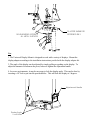
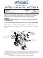
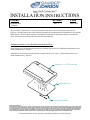
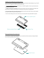
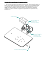
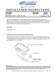
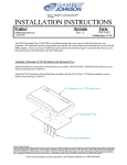
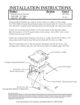
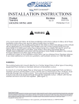
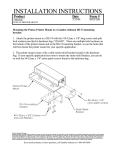
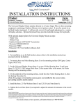
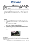
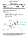
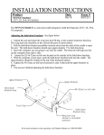
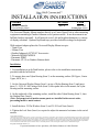
INSTALLATION INSTRUCTIONS
Product
7160-0272, 7160-0723
Universal Display Mount
Revision
Form
INST-492
Rev.A
Printing Spec: PS-001
The Universal Display Mount attaches directly to a Center Upper Pole or other mounting
equipment containing a Gamber-Johnson swivel pattern cutout. It can also mount to an
In-Dash bracket (optional). It will provide swivel, tilt and height adjustment to a variety
of display solutions. Optional keyboard trays provides lockable stowage for keyboards.
With optional adapter plates the Universal Display Mount accepts:
- 75mm Vesa
- 100mm Vesa
- Gamber Johnson 4.09"X2.00" Accessories
- Motorola MW800/MW810
- Panasonic PDRC
- Panasonic CF-19 on Gamber-Johnson dock
Installation:
1. For installation on an In-Dash bracket, please refere to the installation instructions
provided with the In-Dash kit.
2. To mount, place one Nylon Bearing (Item 3) on the mounting surface (DS-Upper, Center
Upper, MCS, etc.).
3. Set the Universal Display Mount (Item 1) on top of Nylon Bearing (Item 3) and insert
three (3) .25-20 X 1.00 Carriage Bolts (Item 2) thru square holes in the mount, the Nylon
Bearing and the mounting surface.
4. On the underside of the mounting surface, install the other Nylon Bearing (Item 3), then
the Backup Plate (Item 4).
(Note: For proper swivel motion ensure parts are installed in the correct order,
preventing metal to metal contact.
5. Install the three .25 Flat Washers (Item 5) and .25-20 Lock Nuts (Item 6).
6. Tighten the Lock Nuts (Item 6) as required to adjust the amount of resistance in the swivel
motion.
Product Mounting Disclaimer
Gamber-Johnson is not liable under any theory of contract or tort law for any loss, damage, personal injury, special, incidental or consequential damages for personal injury or other damage
of any nature arising directly or indirectly as a result of the improper installation or use of its products in vehicle or any other application. In order to safely install and use Gamber-Johnson
products full consideration of vehicle occupants, vehicle systems (i.e., the location of fuel lines, brakes lines, electrical, drive train or other systems), air-bags and other safety equipment is
required. Gamber-Johnson specifically disclaims any responsibility for the improper use or installation of its products not consistent with the original vehicle manufactures specifications
and recommendations, Gamber-Johnson product instruction sheets, or workmanship standards as endorsed through the Gamber-Johnson Certified Installer Program.
© copyright 2010 Gamber-Johnson, LLC
If you need assistance or have questions, call Gamber-Johnson at 1-800-456-6868
2
1
3
NYLON BEARINGS SEPERATE
ALL METAL SURFACES
DS-UPPER SHOWN FOR
REFERENCE ONLY
4
5
6
Use:
1. The Universal Display Mount is designed to work with a variety of displays. Mount the
display adapter according to the installation instructions povided with the display adapter kit.
2. The angle of the display can be adjusted by simply pulling or pushing on the display. To
adjust the amount of tension on the pivot, loosen or tighten the adjustment handle.
4. In severe environments, it may be necessary to lock the display angle. This can be done by
inserting a 1/4" bolt or pin into the provided holes. This will lock the display at 5 degrees.
Adjustement Handle
Display Angle
Lock Holes
INSTALLATION INSTRUCTIONS
Product
Revision
7160-0277
INTERFACE PLATE, CF-19
Rev.A
Form
INST-497
Printing Spec: PS-001
The CF-19 Interface Plate allows a Gamber-Johnson CF-19 docking station (7160-0207) to be
attached to the Universal Display Mount (7160-0272, 7160-0273). Refer to the installation
instructions for the Universal Display Mount for additional installation instructions.
Installation:
1. Following the diagram below, install the CF-19 dock to the Universal Display Plate using
the hardware provided.
2. Using the supplied hardware, install the Plate into the slots in the Universal Display Mount.
3. Adjust the computer to the desired height and tighen the four bolts holding the plate in.
4. Finish installation following the installation instructions provided with the CF-19 docking
station.
SPACER BUSHINGS
INTERFACE PLATE
1/4-20 UNC
LOCK NUTS
& WASHERS
1/4-20 x 2.25
CARRIAGE BOLTS
1/4-20 BOLTS
& WASHERS
Product Mounting Disclaimer
Gamber-Johnson is not liable under any theory of contract or tort law for any loss, damage, personal injury, special, incidental or consequential damages for personal injury or other damage
of any nature arising directly or indirectly as a result of the improper installation or use of its products in vehicle or any other application. In order to safely install and use Gamber-Johnson
products full consideration of vehicle occupants, vehicle systems (i.e., the location of fuel lines, brakes lines, electrical, drive train or other systems), air-bags and other safety equipment is
required. Gamber-Johnson specifically disclaims any responsibility for the improper use or installation of its products not consistent with the original vehicle manufactures specifications
and recommendations, Gamber-Johnson product instruction sheets, or workmanship standards as endorsed through the Gamber-Johnson Certified Installer Program.
© copyright 2010 Gamber-Johnson, LLC
If you need assistance or have questions, call Gamber-Johnson at 1-800-456-6868
INSTALLATION INSTRUCTIONS
Product
Revision
Keyboard Tray
7160-0210
Rev. C
Form
INST-444
The 7160-0210 keyboard tray is a universal keyboard mount that can be used to hold just about any size
keyboard. The keyboard tray has a hole pattern that matches the current Panasonic keyboard that is used with the
PDRC display. There are strips of adhesive backed Dual lock located in the hardware bag for customers that
choose to use the keyboard tray with keyboards other than Panasonic.
Attaching a Panasonic or TG3 Keyboard to the Keyboard Tray:
Attach the Panasonic keyboard to the keyboard tray assembly with the (8) M3 x 8MM flat head machine screws
found in hardware bag 7120-0473.
Attach the TG3 keyboard to the keyboard tray assembly with the (4) 8-32unc x 3/8 flat head machine screws
found in hardware bag 7120-0473.
Panasonic or TG3 keyboard
Keyboard Tray
Mounting Hardware
Product Mounting Disclaimer
Gamber-Johnson is not liable under any theory of contract or tort law for any loss, damage, personal injury, special, incidental or consequential damages for personal injury or other damage
of any nature arising directly or indirectly as a result of the improper installation or use of its products in vehicle or any other application. In order to safely install and use Gamber-Johnson
products full consideration of vehicle occupants, vehicle systems (i.e., the location of fuel lines, brakes lines, electrical, drive train or other systems), air-bags and other safety equipment is
required. Gamber-Johnson specifically disclaims any responsibility for the improper use or installation of its products not consistent with the original vehicle manufactures specifications
and recommendations, Gamber-Johnson product instruction sheets, or workmanship standards as endorsed through the Gamber-Johnson Certified Installer Program.
If you need assistance or have questions, call Gamber-Johnson at 1-800-456-6868
Attaching a universal Keyboard to the Keyboard Tray:
Attach the keyboard to the keyboard tray with the 1" x 10" strips of Dual lock found in hardware bag 7120-0473.
There are (4) 10" long pieces of dual lock in the hardware bag.
1. If not preassembled by the factory; attach the pieces of dual lock together to form two pieces that have the
release liners on the out side.
2. Without removing the release liners place the pair of dual lock strips on the keyboard tray and place the
keyboard on top to make sure the Dual lock is located in the correct place for your application.
3. Once the location of the keyboard has been determined, remove the release liner from one side of the dual
lock strips and attach the strips to the keyboard tray.
4. Remove the remaining release liners from the top sides of the dual lock strips and attach the keyboard.
Various keyboard types
Adhesive backed Dual Lock
Keyboard Tray
Removing the Keyboard Tray from the base:
The keyboard tray with the keyboard attached can be removed from the base mount by loosening the thumb
screws located on the bottom side of the base.
Thumb Screws
Attaching the keyboard mount to the mounting surface:
1. The keyboard mount has a tilt/mounting bracket that allows for mounting the support on
any flat surface ranging from horizontal to vertical. Attach the tilt/mounting bracket using
1/4-20unc hex bolts, washers, and nuts that were provided in hardware bag 7120-0232.
NOTE: The bolt provided may be to long or short for your application. Should that
condition occur please substitute an appropriate length which can be purchased at any
hardware store.
Cover Bracket
Mounting flange for
vertical to 45v
mounting surfaces
Mounting flange for
horizontal to 45v
mounting surfaces
#6-32unc Mounting Hardware