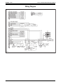
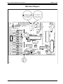
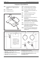
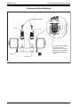
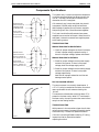
1
○ ○ ○ ○ ○ ○ ○ ○ ○ ○ ○ ○ ○ ○ ○ ○ ○ ○ ○ ○ ○ ○ ○ ○ ○ ○ ○ ○ ○ ○ ○ ○ ○ ○ ○ ○ ○ ○ ○ ○ ○ ○ ○ ○ ○ ○ ○ ○ ○ ○ ○ ○ ○ ○ ○ ○ ○ ○ ○ ○ ○ ○ ○ ○ ○ ○ ○ ○ ○ ○ ○ ○ ○ ○ ○ ○ ○ ○
Service
Manual
Series 12134A/12135A/12136A
Recovery/Recycling/Recharging Unit
For R-12 and R-134A
Theory of Operation and Safety Precautions ......................... 2
Component Descriptions ......................................................... 3
Flow Diagrams ...................................................................... 16
Pictorial Views ...................................................................... 25
Wiring Diagram .................................................................... 28
Main Board Diagram ............................................................ 29
Component Specifications .................................................... 30
Compressor Specifications and Service ............................... 35
Tubing Schematic .................................................................. 36
Troubleshooting ..................................................................... 37
RA19301/RA19246 Replacement Main Board ..................... 51
RA19008 Scale Identification,
Accuracy Check and Recalibration ...................................... 52
Checking the Scale Accuracy ................................................ 52
Recalibrating the Scale ......................................................... 52
Setting the P-1 Pot ................................................................ 52
RA19008 Scale Specifications ............................................... 53
Diagnostic Procedures .......................................................... 54
Function Check ..................................................................... 55
Recovery Check ..................................................................... 55
Evacuation and Recycling Check ......................................... 55
Charging and Scale Check ................................................... 56
Clearing Check ...................................................................... 56
Labor Rates ........................................................................... 57
ORIGINAL 6/1/95
Series 12134A/12135A/12136A Service Manual
Theory of Operation and Safety Precautions
The Series 12134A recovery, recycling, evacuating
and recharge units are designed for R-12 and
R-134A refrigerant only. These units are UL
approved and meet SAE J1770 standards.
These units began production in March of 1995.
The date code and serial number can be found on
a white tag on the back of the unit near the tank.
DEPRESSURIZING THE UNIT
1. Disconnect the black lead wire from the
compressor relay.
2. Connect the 96” blue low side hose to the oil
drain port (if the unit is in the R-134A setting,
you must use a low side coupler connector
and tee supplied to you, part numbers 16301
and 15554).
3. Open both the high and low side manifold
valves on the unit's control panel.
4. Open the oil drain valve.
5. Close the liquid and vapor valves on the
50 lb. tank.
7. Connect the red vapor tank hose to the high
side of a hand held manifold gauge set.
8. Connect the blue liquid tank hose to the low
side of a hand held manifold gauge set.
9. Connect the yellow center port of the hand-held
manifold gauge set to the inlet of a prepared
recovery unit (for R-12, use a 17650, R-134a, use
a 34650). Open the high and low side valves on
the hand-held manifold gauge set.
10. Turn on the unit being serviced (12134A). Press
SHIFT/RESET to access the program mode.
11. Press SHIFT/RESET and “1” at the same time
to start the recycle mode.
12. Start the separate recovery unit (17650
or 34650).
13. When the recovery light on the separate
recovery unit shuts off, wait ten minutes and
watch your hand-held manifold gauge set for a
pressure rise above zero. Repeat Steps 11 and
12 until positive pressure does not develop on
the gauge set.
6. Disconnect all hoses from the 50 lb. tank.
▲ WARNING!
Always wear safety goggles when working with refrigerants. Contact
with refrigerant can cause eye injury. Disconnect lines and hoses with
extreme caution! Pressurized refrigerant may be present in lines and
hoses. Always point lines and hoses away from you and anyone
nearby.
▲ WARNING!
Always unplug the station from the power source before removing any
of the shrouding or beginning any service work.
To order parts please call Robinair Customer Service at 1-419-485-5561.
Or FAX your order to 1-419-485-4330.
All service related questions should be directed to the Robinair
Technical Assistance Line at 1-800-822-5561.
2
Series 12134A/12135A/12136A Service Manual
ORIGINAL 6/1/95
Component Descriptions
RECOVERY
1. 18190A R-134a Low Side Coupler (blue
actuator, smaller I.D.) — Allows access to the
low side on an R-134a system.
RA19115 Replacement Front O-Ring Only
2. RA19329 R-134a Low Side Hose — Provides
flow from the low side coupler to the low side
port on the unit (14mm x 1/2 Acme Quick Seal).
17773 Replacement R-134a Quick Seal O-Ring
17772 Coupler O-Ring
2. RA19309 (R-12) 96” Blue Hose Double Quick
Seal — Low side service hose to the vehicle.
18180 Replacement Quick Seal O-Ring
40300 Quick Seal Repair Kit
3. 40352 Schraeder Core — Package of six (6)
replacement Schraeder valves.
4. RA19279 (RA19319 metric) 23/4 Low Side
Gauge — Used to read pressure entering the
low side hose.
RA19257 23/4 Replacement Gauge Lens
5. RA19044 Low Side Manifold Valve — Allows
flow from the low side hose to the center
manifold port.
6. 18191A R-134a High Side Coupler (red
actuator, larger I.D.) — Allows access to the
high side on an R-134a system.
RA19115 Replacement Front O-Ring Only
7. RA19328 R-134a High Side Hose — Provides
flow from the high side coupler to the high side
port of the unit (14mm x 1/2 Acme Quick Seal).
17773 Replacement R-134a Quick Seal O-Ring
17772 Coupler O-Ring
7. RA19308 (R-12) 96” Red Hose Double Quick
Seal — High side service hose to the vehicle.
18180 Replacement R-12 Quick Seal O-Ring
40300 Quick Seal Repair Kit
3. 40352 Schraeder Core — Package of six (6)
replacement Schraeder valves.
8. RA19280 (RA19318 metric) 23/4 High Side
Gauge — Used to read pressure entering the
high side hose.
RA19257 23/4 Replacement Gauge Lens
9. RA19044 High Side Manifold Valve — Allows
flow from the high side hose to the center
manifold port.
10. RA19266 Vacuum Pump Protection Switch —
A normally open sensor that closes when
pressure greater than 25 psi is present in the
A/C system. If the pressure is less then 25 psi
in the recovery mode, the display reads
“CH-P.” In the vacuum mode the display reads
“U-HI” if the pressure is 25 psi or greater in
the A/C system. This indicates that a recovery
procedure must be performed before attempting to vacuum.
11. RA19330 Suction Line Strainer — Filters the
refrigerant coming from the high and low side
manifold valves before entering into the
manifold assembly.
41. RA19320 (RA19321 220 volt) Manifold Assembly
— Block assembly that houses the recovery,
recycling, charging and vacuum solenoids; this
manifold also houses the vacuum sensor and
three check balls. In the recovery mode
solenoids 30 (Vacuum), 37 (Recycling), and 39
(Charging) are all closed (no power is supplied).
Note: RA19258 Solenoid Rebuild Kits are
available for all of the solenoids in this
manifold block.
RA19236 Check Ball with Spring
12. RA19258 Recovery Solenoid Rebuild Kit — A
normally closed solenoid designed to prevent
the flow of refrigerant into the system oil
separator while the unit is turned off or in any
mode other then recovery.
13. RA17328 Vacuum Sensor — A normally closed
sensor designed to open when a 17” vacuum is
reached in the inlet manifold.
14. RA18760 System Oil Separator — Performs
three functions. Internal heat causes incoming
saturated vapor to evaporate. This is important
to insure that no liquid enters the compressor
and that oil droplets contained in the refrigerant
will drop out in the separator. The third function
will be discussed later.
15. RA19291 Oil Drain Valve — Allows the oil
removed from the system to be drained when
recovery is complete. The same amount of oil
should be returned during charging.
3
ORIGINAL 6/1/95
Series 12134A/12135A/12136A Service Manual
Component Descriptions
Note: It is very important that the oil drain
procedure be done after each recovery.
RA17419 Oil Drain Bottle
16. 34430 Filter Drier — Removes moisture, acid
and oil from the refrigerant.
40084 Replacement Hose Gasket
17. RA19302 (RA19314 220 volt) Compressor —
Converts a low pressure entering gas into a high
pressure exiting gas. This is a 1/3 horse power
oil-less compressor. To help eliminate vibration,
this is a hose-plumbed compressor with flare
connections on the unit end of the hose.
18. RA17416 (RA17516 220 volt) Fan — Assists in
cooling the compressor during normal operation.
19. RA19331 (RA19327 220 volt) High Side Diversion Solenoid — A three-way normally closed
solenoid. During normal operation the refrigerant passes through to the system oil separator
(ports 1 and 3). In the self clearing mode the
solenoid is energized passing the refrigerant
directly to the discharge solenoid of the
selected refrigerant type (ports 1 and 2).
20. RA17529 High Pressure Cut Out — A normally
closed sensor that turns off the unit when the
discharge pressure reaches 435 psi.
Note: This switch has three contacts; the outer
two contacts (numbered 1 and 3) are normally
closed and have two solid red wires attached
to them.
21. RA17522 (RA17578 220 volt) Pressure Equalizing Solenoid — A normally open solenoid
that allows the suction and discharge pressures on the compressor to equalize and forces
pressure down on the oil separator to drain the
oil recovered from the A/C system when the
solenoid loses power. This solenoid receives
power whenever the compressor is running.
14. RA18760 System Oil Separator — At this point
high pressure, high temperature vapor enters
the separator and passes through a condensing
coil. The vapor cools and condenses by giving up
heat to the incoming refrigerant.
22. RA19198 R-12 Auto Air Purge Device —
Liquid refrigerant is circulated through the
upper section during recycling to establish a
reference pressure.
4
22a.RA19242 R-134a Auto Air Purge Device —
Liquid refrigerant is circulated through the
upper section during recycling to establish a
reference pressure.
23. RA19287 Recovery Check Valve (1/4 MFL x 1/8
MPT) — Allows flow in one direction only and
prevents refrigerant in the tank from coming
back into the unit during shutdown.
24. RA19006 (RA19088 220 volt) Discharge
Solenoid (R-12 or R-134a) — A normally
closed solenoid that allows refrigerant flow to
the vapor side of the tank for the selected
refrigerant type only.
RA19258 Solenoid Rebuild Kit
25. RA19282 Recovery Check Valve (1/8 MPT x 1/8
MPT) — Allows flow in one direction only and
prevents refrigerant in the tank from coming
back into the unit during shut down.
26. RA19312 (R-12) or RA19307 (R-134a) 36” Red
Tank Hose — Delivers refrigerant being
recovered or recycled to the vapor side of the
50 lbs. tank.
18180 Replacement R-12 Quick Seal O-Ring
40300 Quick Seal Repair Kit (R-12 only)
17773 Replacement R-134a Quick Seal O-Ring
27. 17506 (R-12) or 34750 (R-134a) Refillable
Refrigerant Tank — Stores refrigerant to be
recycled later.
29. RA19310 (R-12) or RA19313 (R-134a) Air
Purge Hose — Supplies pressure from the top
of the recovery tank to the air purge control.
18180 Replacement R-12 Quick Seal O-Ring
40300 Quick Seal Repair Kit (R-12 only)
17773 Replacement R-134a Quick Seal O-Ring
38. RA19006 (RA19088 220 volt) Air Purge Solenoids (R-12 or R-134a) — Prevents flow of
refrigerant into the lower cavity of the air purge
device of the selected refrigerant type until
energized 60 seconds after the recycling process
has been engaged.
Note: Power is dropped from the solenoid after
10 minutes of purging.
RA19258 Solenoid Rebuild Kit
Series 12134A/12135A/12136A Service Manual
ORIGINAL 6/1/95
Component Descriptions
EVACUATION
1. 18190A R-134a Low Side Coupler (blue actuator, smaller I.D.) — Allows access to the low side
on an R-134a system.
RA19115 Replacement Front O-Ring Only
2. RA19329 R-134a Low Side Hose — Provides
flow from the low side coupler to the low side
port on the unit (14mm x 1/2 Acme Quick Seal).
17773 Replacement R-134a Quick Seal O-Ring
17772 Coupler O-Ring
2. RA19309 (R-12) 96” Blue Hose Double Quick
Seal — Low side service hose to the vehicle.
18180 Replacement Quick Seal O-Ring
40300 Quick Seal Repair Kit
3. 40352 Schraeder Core — Package of six (6)
replacement Schraeder valves.
4. RA19279 (RA19319 metric) 23/4 Low Side Gauge —
Used to read pressure entering the low side hose.
RA19257 23/4 Replacement Gauge Lens
5. RA19044 Low Side Manifold Valve — Allows flow
from the low side hose to the center manifold port.
6. 18191A R-134a High Side Coupler (red actuator, larger I.D.) — Allows access to the high side
on an R-134a system.
RA19115 Replacement Front O-Ring Only
7. RA19328 R-134a High Side Hose — Provides
flow from the high side coupler to the high side
port of the unit (14mm x 1/2 Acme Quick Seal).
17773 Replacement R-134a Quick Seal O-Ring
17772 Coupler O-Ring
7. RA19308 (R-12) 96” Red Hose Double Quick
Seal — High side service hose to the vehicle.
18180 Replacement R-12 Quick Seal O-Ring
40300 Quick Seal Repair Kit
3. 40352 Schraeder Core — Package of six (6)
replacement Schraeder valves.
8. RA19280 (RA19318 metric) 23/4 High Side
Gauge — Used to read pressure entering the
high side hose.
RA19257 23/4 Replacement Gauge Lens
10. RA19266 Vacuum Pump Protection Switch —
A normally open sensor that closes when pressure greater than 25 psi is present in the A/C
system. If the pressure is less then 25 psi in the
recovery mode, the display reads “CH-P.” In the
vacuum mode the display reads “U-HI” if the
pressure is 25 psi or greater in the A/C system.
This indicates that a recovery procedure must be
performed before attempting to vacuum.
11. RA19330 Suction Line Strainer — Filters the
refrigerant coming from the high and low side
manifold valves before entering into the
manifold assembly.
41. RA19320 (RA19321 220 volt) Manifold
Assembly — Block assembly that houses the
recovery, recycling, charging and vacuum
solenoids; this manifold also houses the
vacuum sensor and three check balls. In the
evacuation mode solenoids 12 (Recovery), 37
(Recycling), and 39 (Charging) are all closed
(no power supplied).
Note: RA19258 Solenoid Rebuild Kits are
available for all of the solenoids in this
manifold block.
RA19236 Check Ball with Spring
30. RA19258 Vacuum Solenoid Rebuild Kit —
Normally closed solenoid designed to prevent
flow to the vacuum pump during recovery or
charging.
31. 111877 Vacuum Hose — Provides flow from
the vacuum solenoid to the intake of the
vacuum pump.
40084 Replacement Hose Gasket
32. RA15425 (RA15428 220 volt) Vacuum pump —
A 6 CFM, two stage rotary vane pump designed
to pull moisture and air from an A/C system.
13203 Pump Oil
15369 Base and Foot Assembly
33. RA19323 (R-12) or RA19322 (R-134a) Oil
Injector Assembly — Controls the flow of oil
from the injection bottle to the vehicle.
113025 Oil Injector Check Valve
RA19141 Oil Bottle
RA19291 Replacement Valve
9. RA19044 High Side Manifold Valve — Allows
flow from the high side hose to the center
manifold port.
5
ORIGINAL 6/1/95
Series 12134A/12135A/12136A Service Manual
Component Descriptions
RECYCLING
27. 17506 (R-12) or 34750 (R-134a) Refillable
Refrigerant Tank — Stores refrigerant to be
recycled later.
28. RA19311 (R-12) or RA19306 (R-134a) 36” Blue
Tank Hose — Allows flow from the liquid side
of the tank to the liquid solenoid.
18180 Replacement R-12 Quick Seal O-Ring
40300 Quick Seal Repair Kit (R-12 only)
17773 Replacement R134a Quick Seal O-Ring
3. 40352 Schraeder Core — Package of six (6)
replacement Schraeder valves.
40. 107021 Liquid Line Strainer — Filters liquid
coming from the blue tank hose before going to
the liquid solenoid. This strainer is a filter
screen that is installed between the liquid
solenoid and the bulkhead fitting (see page 32
for details).
34. RA19006 (RA19088 220 volt) Liquid Solenoid —
Allows flow to the expansion valve and recycle
solenoid of the selected refrigerant type only.
RA19258 Solenoid Rebuild Kit
35. RA17577 Moisture Indicator — References
the moisture content of the refrigerant being
recycled. Pale yellow indicates wet; light mint
green indicates dry. During recycling the
moisture indicator is normally filled with
liquid refrigerant and warm to the touch.
43. RA19288 Manifold By-Pass Check Valve (1/8
MPT x 1/4 MFL) — Prevents flow during the
recovery, recycle and charging mode to the
manifold bypass solenoid.
36. RA19316 Expansion Valve and Tube —
Converts incoming liquid refrigerant into a low
pressure saturated vapor. The calibration of the
expansion valve can be checked at the oil drain
port with a pressure gauge. The tolerance of the
valve is 30 to 40 psi and minimum recycling
time is five minutes before checking.
6
41. RA19320 (RA19321 220 volt) Manifold
Assembly — Block assembly that houses the
recovery, recycling, charging and vacuum
solenoids; this manifold also houses the
vacuum sensor and three check balls. In the
recycling mode solenoids 12 (Recovery), 30
(Vacuum), and 39 (Charging) are all closed (no
power supplied).
Note: RA19258 Solenoid Rebuild Kits are
available for all of the solenoids in this
manifold block.
RA19236 Check Ball with Spring
37. RA19258 Recycling Solenoid Rebuild Kit — A
normally closed solenoid that prevents the flow
of refrigerant into the system oil separator
while the unit is turned off or in any mode
other then recycling.
13. RA17328 Vacuum Sensor — A normally closed
sensor designed to open when a 17” vacuum is
reached in the inlet manifold.
14. RA18760 System Oil Separator — Performs
three functions. Internal heat causes incoming
saturated vapor to evaporate. This is important
to insure that no liquid enters the compressor
and that oil droplets contained in the refrigerant
drop out in the separator. The third function will
be discussed later.
15. RA19291 Oil Drain Valve — Allows the oil
removed from the system to be drained when
recovery is complete. The same amount of oil
should be returned during charging.
Note: It is very important that the oil drain
procedure be done after each recovery.
RA17419 Oil Drain Bottle
16. 34430 Filter Drier — Removes moisture, acid
and oil from the refrigerant.
40084 Replacement Hose Gasket
17. RA19302 (RA19314 220 volt) Compressor —
Converts a low pressure entering gas into a high
pressure exiting gas. This is a 1/3 horse power
oil- less compressor. To help eliminate vibration
this is a hose-plumbed compressor with flare
connections on the unit end of the hose.
Series 12134A/12135A/12136A Service Manual
ORIGINAL 6/1/95
Component Descriptions
18. RA17416 (RA17516 220 volt) Fan — Assists in
cooling the compressor during normal operation.
19. RA19331 (RA19327 220 volt) High Side
Diversion Solenoid — A three-way normally
closed solenoid. During normal operation the
refrigerant passes through to the system oil
separator (ports 1 and 3). In the self clearing
mode the solenoid is energized passing the
refrigerant directly to the discharge solenoid
of the
selected refrigerant type (ports 1 and 2).
20. RA17529 High Pressure Cut Out — A normally
closed sensor that turns off the unit when the
discharge pressure reaches 435 psi.
Note: This switch has three contacts; the outer
two contacts (numbered 1 and 3) are normally
closed and have two solid red wires attached
to them.
21. RA17522 (RA17578 220 volt) Pressure Equalizing Solenoid — A normally open solenoid that
allows the suction and discharge pressures on
the compressor to equalize and forces pressure
down on the oil separator to drain the oil
recovered from the A/C system when the
solenoid loses power. This solenoid receives
power whenever the compressor is running.
14. RA18760 System Oil Separator — At this point
high pressure, high temperature vapor enters
the separator and passes through a condensing
coil. The vapor cools and condenses by giving up
heat to the incoming refrigerant.
22. RA19198 R-12 Auto Air Purge Device —
Liquid refrigerant is circulated through the
upper section during recycling to establish a
reference pressure.
22a.RA19242 R-134a Auto Air Purge Device —
Liquid refrigerant is circulated through the
upper section during recycling to establish a
reference pressure.
23. RA19287 Recovery Check Valve (1/4 MFL x
1/8 MPT) — Allows flow in one direction only
and prevents refrigerant in the tank from
coming back into the unit during shutdown.
24. RA19006 (RA19088 220 volt) Discharge
Solenoid (R-12 or R-134a) — A normally closed
solenoid that allows refrigerant flow to the
vapor side of the selected refrigerant type only.
RA19258 Solenoid Rebuild Kit
25. RA19282 (Recovery Check Valve (1/8 MPT x
1/8 MPT) — Allows flow in one direction only
and prevents refrigerant in the tank from
coming back into the unit during shutdown.
26. RA19312 (R-12) or RA19307 (R-134a) 36” Red
Tank Hose — Delivers refrigerant being
recovered or recycled to the vapor side of the
50 lb. tank.
18180 Replacement R-12 Quick Seal O-Ring
40300 Quick Seal Repair Kit (R-12 Only)
17773 Replacement R-134a Quick Seal O-Ring
27. 17506 (R-12) or 34750 (R-134a) Refillable
Refrigerant Tank — Stores refrigerant to be
recycled later.
28. RA19310 (R-12) or RA19313 (R-134a) Air
Purge Hose — Supplies pressure from the top
of the recovery tank to the air purge control.
18180 Replacement R-12 Quick Seal O-Ring
40300 Quick Seal Repair Kit (R-12 Only)
17773 Replacement R-134a Quick Seal O-Ring
38. RA19006 (RA19088 220 volt) Air Purge Solenoids (R-12 or R-134a) — Prevents flow of
refrigerant into the lower cavity of the air purge
device of the selected refrigerant type until
energized 60 seconds after the recycling process
has been engaged.
Note: Power is dropped from the solenoid after
10 minutes of purging.
RA19258 Solenoid Rebuild Kit
22. RA19198 (R-12) or RA19242 (R-134a) Auto Air
Purge Device — After the recycling sequence
has been running for 60 seconds, a timer (programed in the main board) opens the normally
closed solenoid of the selected refrigerant type
allowing pressure to enter the lower cavity of the
air purge device. When the pressure on the
lower cavity exceeds the pressure of the upper
cavity by 7 psi or more, a valve inside the device
opens to release the air pressure out of the
cavity. When the pressures come within 3 psi of
each other, the device stops purging.
7
ORIGINAL 6/1/95
Series 12134A/12135A/12136A Service Manual
Component Descriptions
CHARGING
26. 17506 (R-12) or 34750 (R-134a) Refillable
Refrigerant Tank — Stores refrigerant.
27. RA19311 (R-12) or RA19306 (R-134a) 36” Blue
Tank Hose — Allows flow from the liquid side
of the tank to the liquid solenoid.
18180 Replacement R-12 Quick Seal O-Ring
40300 Quick Seal Repair Kit
17773 Replacement R134a Quick Seal O-Ring
3. 40352 Schraeder Core — Package of six (6)
replacement Schraeder valves.
40. 107021 Liquid Line Strainer — Filters liquid
coming from the blue tank hose before going to
the liquid solenoid. This strainer is a filter screen
that is installed between the liquid solenoid and
the bulkhead fitting (see page 32 for details).
34. RA19006 (RA19088 220 volt) Liquid Solenoid —
Allows flow to the expansion valve and recycle
solenoid of the selected refrigerant type only.
RA19258 Solenoid Rebuild Kit
35. RA17577 Moisture Indicator — References
the moisture content of the refrigerant being
recycled. Pale yellow indicates wet; light mint
green indicates dry. During recycling the
moisture indicator is normally filled with
liquid refrigerant and warm to the touch.
41. RA19320 (RA19321 220 volt) Manifold
Assembly — Block assembly that houses the
recovery, recycling, charging and vacuum
solenoids; this manifold also houses the vacuum
sensor and three check balls. In the charging
mode solenoids 12 (Recovery), 30 (Vacuum), and
37 (Recycling) are all closed (no power supplied).
Note: RA19258 Solenoid Rebuild Kits are
available for all of the solenoids in this
manifold block.
RA19236 Check Ball with Spring
39. RA19258 Charging Solenoid Rebuild Kit —
Normally closed solenoid preventing flow to
the A/C system when the unit is turned off or
in any mode other then charging.
11. RA19330 Suction Line Strainer — Filters the
refrigerant coming from the high and low side
manifold valves before entering into the
manifold assembly.
10. RA19266 Vacuum Pump Protection Switch —
A normally open sensor that closes when pressure greater than 25 psi is present in the A/C
system. If the pressure is less then 25 psi in the
recovery mode, the display reads “CH-P.” In the
vacuum mode the display reads ‘“U-HI” if the
pressure is 25 psi or greater in the A/C system.
This indicates that a recovery procedure must be
performed before attempting to vacuum.
5. RA19044 Low Side Manifold Valve — Allows
flow from the low side hose to the center
manifold port.
9. RA19044 High Side Manifold Valve — Allows
flow from the high side hose to the center
manifold port.
4. RA19279 (RA19319 metric) 23/4 Low Side
Gauge — Used to read pressure entering the
low side hose.
RA19257 23/4 Replacement Gauge Lens
8. RA19280 (RA19318 metric) 23/4 High Side
Gauge — Used to read pressure entering the
high side hose.
RA19257 23/4 Replacement Gauge Lens
3. 40352 Schraeder core — Package of six (6)
replacement Schraeder valves.
2. RA19329 R-134a Low Side Hose — Provides
flow from the low side coupler to the low side
port on the unit (14mm x 1/2 Acme Quick Seal).
17773 Replacement R-134a Quick Seal O-Ring
17772 Coupler O-Ring
2. RA19309 96” (R-12) Blue Hose Double Quick
Seal — Low side service hose to the vehicle.
18180 Replacement Quick Seal O-Ring
40300 Quick Seal Repair Kit
1. 18190A R-134a Low Side Coupler (blue
actuator, smaller I.D.) — Allows access to the
low side on an R-134a system.
RA19115 Replacement Front O-Ring Only
8
Series 12134A/12135A/12136A Service Manual
ORIGINAL 6/1/95
Component Descriptions
3. 40352 Schraeder Core — Package of six (6)
replacement Schraeder valves.
7. RA19328 R-134a High Side Hose — Provides
flow from the high side coupler to the high
side port of the unit. (14mm x 1/2 Acme Quick
Seal)
17773 Replacement R-134a Quick Seal ORing
17772 Coupler O-Ring
7. RA19308 96” (R-12) Red Hose Double Quick
Seal — High side service hose to the vehicle.
18180 Replacement R-12 Quick Seal O-Ring
40300 Quick Seal Repair Kit
6. 18191A R-134a High Side Coupler (red actuator, larger I.D.) — Allows access to the high
side on an R-134a system.
RA19115 Replacement Front O-Ring Only
9
ORIGINAL 6/1/95
Series 12134A/12135A/12136A Service Manual
Component Descriptions
SELF CLEARING FIRST STAGE 10 MINUTES
COMPRESSOR ONLY
1. 18190A R-134a Low Side Coupler (blue actuator, smaller I.D.) — Allows access to the low
side on an R-134a system. Coupler is closed in
the self clearing mode.
RA19115 Replacement Front O-Ring Only
2. RA19329 R-134a Low Side Hose — Provides
flow from the low side coupler to the low side
port on the unit. (14mm x 1/2 Acme Quick Seal)
17773 Replacement R-134a Quick Seal O-Ring
17772 Coupler O-Ring
2. RA19309 96” (R-12) Blue Hose Double Quick
Seal — Low side service hose to the vehicle.
Hose is disconnected from vehicle in the self
clearing mode.
18180 Replacement Quick Seal O-Ring
40300 Quick Seal Repair Kit
3. 40352 Schraeder Core — Package of six (6)
replacement Schraeder valves.
4. RA19279 (RA19319 metric) 23/4 Low Side
Gauge — Used to read pressure entering the
low side hose.
RA19257 23/4 Replacement Gauge Lens
5. RA19044 Low Side Manifold Valve — Allows
flow from the low side hose to the center manifold port. Valve is open in the self clearing mode.
6. 18191A R-134a High Side Coupler (red actuator, larger I.D.) — Allows access to the high
side on an R-134a system. Coupler is closed in
the self clearing mode.
RA19115 Replacement Front O-Ring Only
7. RA19328 R-134a High Side Hose — Provides
flow from the high side coupler to the high side
port of the unit (14mm x 1/2 Acme Quick Seal).
17773 Replacement R-134a Quick Seal O-Ring
17772 Coupler O-Ring
7. RA19308 (R-12) 96” Red Hose Double Quick
Seal — High side service hose to the vehicle.
Hose is disconnected from the vehicle in the
self clearing mode.
18180 Replacement R-12 Quick Seal O-Ring
40300 Quick Seal Repair Kit
10
3. 40352 Schraeder Core — Package of six (6)
replacement Schraeder valves.
8. RA19280 (RA19318 metric) 23/4 High Side
Gauge — Used to read pressure entering the
high side hose.
RA19257 23/4 Replacement Gauge Lens
9. RA19044 High Side Manifold Valve — Allows
flow from the high side hose to the center
manifold port. Valve is open in the self
clearing mode.
10. RA19266 Vacuum Pump Protection Switch —
A normally open sensor that closes when pressure greater than 25 psi is present in the A/C
system. If the pressure is less then 25 psi in the
recovery mode, the display reads “CH-P.” In the
vacuum mode the display reads “U-HI” if the
pressure is 25 psi or greater in the A/C system.
This indicates that a recovery procedure must be
performed before attempting to vacuum.
11. RA19330 Suction Line Strainer — Filters the
refrigerant coming from the high and low side
manifold valves before entering into the
manifold assembly.
12. RA19258 Recovery Solenoid Rebuild Kit — A
normally closed solenoid designed to prevent
the flow of refrigerant into the system oil
separator while the unit is turned off or in any
mode other then recovery.
13. RA17328 Vacuum Sensor — A normally closed
sensor designed to open when a 17” vacuum is
reached in the inlet manifold.
34. RA19006 (RA19088 220 volt) Liquid Solenoid
— A normally closed solenoid that allows flow
to the expansion valve and charging solenoid of
the selected refrigerant type only.
RA19258 Solenoid Rebuild Kit
35. RA17577 Moisture Indicator — References
the moisture content of the refrigerant being
recycled. Pale yellow indicates wet; light
mint green indicates dry. During recycling
the moisture indicator is normally filled with
liquid refrigerant and warm to the touch.
Series 12134A/12135A/12136A Service Manual
ORIGINAL 6/1/95
Component Descriptions
43. RA19288 Manifold By-pass Check Valve (1/8
MPT x 1/4 MFL) — Prevents flow during the
recovery, recycle and charging mode to the
manifold by pass solenoid.
36. RA19316 Expansion Valve and Tube —
Converts incoming liquid refrigerant into a low
pressure saturated vapor. The calibration of the
expansion valve can be checked at the oil drain
valve with a pressure gauge. The tolerance
of the valve is 30 to 40 psi and minimum
recycling time is five minutes before checking.
37. RA19258 Recycling Solenoid Rebuild Kit — A
normally closed solenoid that prevents the flow
of refrigerant into the system oil separator
when the unit is not in the recycling mode.
38. RA19258 Charging Solenoid Rebuild Kit —
Normally closed solenoid preventing flow to
the A/C system when the unit is turned off or
in any mode other then charging.
41. RA19320 (RA19321 220 volt) Manifold
Assembly — Block assembly that houses the
recovery, recycling, charging and vacuum
solenoids; this manifold also houses the vacuum
sensor and three check balls. In the first ten
minute stage of self clearing, solenoids 12
(Recovery), 37 (Recycle), and 39 (Charging) are
all open (receiving power). This block assembly
allows the compressor to totally remove all the
refrigerant from the unit to change from one
refrigerant type to the next.
Note: RA19258 Solenoid Rebuild Kits are
available for all of the solenoids in this
manifold block.
RA19236 Check Ball with Spring
30. RA19258 Vacuum Solenoid Rebuild Kit —
Normally closed solenoid designed to prevent
flow to the vacuum pump during recovery or
charging (no power supplied).
14. RA18760 System Oil Separator — Performs
three functions. Internal heat causes saturated
vapor to evaporate. This is important to insure
that no liquid enters the compressor and that
oil droplets contained in the refrigerant will
drop out in the separator. The third function
will be discussed later.
15. RA19291 Oil Drain Valve — Allows the oil
removed from the system to be drained when
recovery is complete. The same amount of oil
should be returned during charging.
Note: It is very important that the oil drain
procedure be done after each recovery.
RA17419 Oil Drain Bottle
16. 34430 Filter Drier — Removes moisture, acid
and oil from the refrigerant.
40084 Replacement Hose Gasket
23. RA19287 Recovery Check Valve (1/4 MFL x
1/8 MPT) — Allows flow in one direction only
and prevents refrigerant in the tank from
coming back into the unit during shutdown.
22. RA19198 R-12 Auto Air Purge Device —
Liquid refrigerant is circulated through the
upper section during recycling to establish a
reference pressure.
22a.RA19242 R-134a Auto Air Purge Device —
Liquid refrigerant is circulated through the
upper section during recycling to establish a
reference pressure.
14. RA18760 System Oil Separator — At this
point high pressure, high temperature vapor
enters the separator and passes through a
condensing coil. The vapor cools and condenses
by giving up heat to the incoming refrigerant.
20. RA17529 High Pressure Cut Out — A normally
closed sensor that turns off the unit when the
discharge pressure reaches 435 psi.
Note: This switch has three contacts; the outer
two contacts (numbered 1 and 3) are normally
closed and have two solid red wires attached
to them.
19. RA19327 (117327 220 volt) High Side
Diversion Solenoid — A three-way normally
closed solenoid. During normal operation the
refrigerant passes through to the system oil
separator. In the self clearing mode the
solenoid is energized passing the refrigerant
directly to the discharge solenoid of the
selected refrigerant type. Refrigerant back
seats against port 3.
11
ORIGINAL 6/1/95
Series 12134A/12135A/12136A Service Manual
Component Descriptions
21. RA17522 (RA17578 220 volt) Pressure Equalizing Solenoid — A normally open solenoid
that allows the suction and discharge pressures on the compressor to equalize and forces
pressure down on the oil separator to drain the
oil recovered from the A/C system when the
solenoid loses power. This solenoid does not
receive power in the self clearing mode.
17. RA19302 (RA19314 220 volt) Compressor —
Converts a low pressure entering gas into a
high pressure exiting gas. This is a 1/3 horse
power oil-less compressor. To help eliminate
vibration this is a hose plumbed compressor
with flare connections on the unit end of the
hose. In the first stage of the self clearing the
compressor runs for a minimum of ten minutes
and until a 17” vacuum is reached at the
vacuum sensor.
18. RA17416 (RA17516 220 volt) Fan — Assists in
cooling the compressor during normal operation.
19. RA19331 (RA19327 220 volt) High Side Diversion Solenoid — A three way normally closed
solenoid. During normal operation the
refrigerant passes through to the system oil
separator. In the self clearing mode the solenoid is energized passing the refrigerant
directly to the discharge solenoid of the
selected refrigerant type (ports 1 and 2).
41. RA19006 (RA19088 220 volt) Manifold
By-pass Solenoid — A normally closed solenoid
that opens only in the second ten minutes of the
self clearing process. This solenoid opens allowing access to the discharge of the compressor
when the vacuum pump starts running.
RA19258 Solenoid Rebuild Kit
12
23. RA19287 Recovery Check Valve (1/8 MPT x
1/4 MFL) — Allows flow in one direction only
and prevents refrigerant in the tank from
coming back into the unit during shutdown.
24. RA19006 (RA19088 220 volt) Discharge
Solenoid (R-12 or R-134a) — Allows refrigerant flow to the red vapor side of the selected
refrigerant type only.
RA19258 Solenoid Rebuild Kit
25. RA19282 Recovery Check Valve (1/8 MPT x
1/8 MPT) — Allows flow in one direction only
and prevents refrigerant in the tank from
coming back into the unit during shutdown.
26. RA19312 (R-12) or RA19307 (R-134a) 36” Red
Tank Hose — Delivers refrigerant being
recovered or recycled to the vapor side of the
50 lbs. tank.
18180 Replacement R-12 Quick Seal O-Ring
40300 Quick Seal Repair Kit (R-12)
17773 Replacement R-134a Quick Seal O-Ring
27. 17506 (R-12) or 34750 (R-134a) Refillable
Refrigerant Tank — Stores refrigerant.
Series 12134A/12135A/12136A Service Manual
ORIGINAL 6/1/95
Component Descriptions
SELF CLEARING SECOND STAGE 10 MINUTES
VACUUM PUMP ONLY
In the second stage of the self clearing mode
everything is the same as in the first stage with
the exception that:
A. The 17 (Compressor) and 24 (Discharge)
solenoids are not powered.
B. The following items are allowing flow.
42. RA19006 (RA19088 220 volt) Manifold
By-Pass Solenoid — A normally closed solenoid
that opens only in the second ten minutes of the
self clear process. This solenoid opens allowing
access to the discharge of the compressor when
the vacuum pump starts running.
RA19258 Solenoid Rebuild Kit
43. RA19288 Manifold By-Pass Check Valve
(1/8 MPT x 1/4 MFL) —Prevents flow during the
recovery, recycle and charging mode to the manifold by-pass solenoid.
41. RA19320 (RA19321 220 volt) Manifold
Assembly — Block assembly that houses the
recovery, recycling, charging and vacuum
solenoids; this manifold also houses the vacuum
sensor and three check balls. In the second ten
minute stage of self clearing, solenoids 12
(Recovery), 30 (Vacuum), 37 (Recycle), and 39
(Charging) are all open (receiving power). This
block assembly allows the vacuum pump to
remove any moisture or air from the unit to
change from one refrigerant type to the next.
Note: RA19258 Solenoid Rebuild Kits are
available for all of the solenoids in this
manifold block.
RA19236 Check Ball with Spring
30. RA19258 Vacuum Solenoid Rebuild Kit —
Normally closed solenoid preventing flow to
the vacuum pump during recovery or charging.
31. 111877 Vacuum Hose — Provides flow from
the vacuum solenoid to the intake of the
vacuum pump.
40084 Replacement Hose Gasket
32. RA15425 (RA15428 220 volt) Vacuum pump
— A 6 CFM, two stage rotary vane pump
designed to pull moisture and air from an A/C
system. In the self clearing mode the pump
pulls a vacuum on the recovery unit.
13
ORIGINAL 6/1/95
Series 12134A/12135A/12136A Service Manual
Component Descriptions
ELECTRICAL
10. RA19266 Vacuum Pump Protection Switch —
A normally open sensor that closes when
pressure greater than 25 psi is present in the
A/C system. If the pressure is less then 25 psi in
the recovery mode, the display reads “CH-P.” In
the vacuum mode the display reads “U-HI” if the
pressure is 25 psi or greater in the A/C system.
This indicates that a recovery procedure must be
performed before attempting to vacuum.
13. RA17328 Vacuum Sensor — A normally closed
sensor that sends a signal to the main board
when a 17” vacuum has been reached in the
inlet line. The switch has two orange wires
attached to it.
18. RA17416 (RA17516 220 volt) Fan — Cools the
cabinet temperature.
20. RA17529 High Pressure Cut Out — A normally
closed sensor that turns off the unit when the
discharge pressure reaches 435 psi. This switch
has three contacts: the outer two contacts
(numbered 1 and 3) are normally closed.
14
44. RA40994 (RA17135 220 volt) Main Power
Switch — Controls the power between the
power cord and the main board.
45. RA19301 (RA19246 220 volt) Main Board —
Controls the unit function, automatic or
programmed.
46. RA19008 Scale — Sends a signal to the main
board for accurate weight readings and tank
overfill protection.
47. RA19253 Keypad — Programs the main board.
48. RA17459 (RA17324 220 volt) System Relays
— Energizes the compressor and vacuum
pump allowing the sensors to turn off the
machine. The relay has two sets of contacts
which close when the coil is energized.
50. 117334 Power Entry Connector — Female
socket where the power cord connects.
51. RA19303 (117581 220 volt) Power Cord —
Provides power to the unit.
Series 12134A/12135A/12136A Service Manual
ORIGINAL 6/1/95
15
ORIGINAL 6/1/95
Series 12134A/12135A/12136A Service Manual
Flow Diagram
4
5
10
8
9
13
11
22
22a
41
31
32
36
38 38a
43
35
1/4
FARE
R-12
14
HIGH
16
3
INLET
3
15
LOW
17
24
25 GAS
20
18
19
23
42
3
34
LIQUID
PURGE
1/2
ACME
134a
HIGH 3
INLET
3
= SCHRAEDER CORE
LOW
24a
GAS
25
3
LIQUID
34a
PURGE
21
SLIDING DOOR TO EXPOSE R-12 FITTINGS OR 134a
FITTINGS BUT NEVER BOTH AT THE SAME TIME
12134a
16
TANK CONNECTIONS
MANUALLY CHANGED
FROM R-12 TO 134a
Series 12134A/12135A/12136A Service Manual
ORIGINAL 6/1/95
Flow Diagram
3. 40352 Schraeder Core
4. RA19279 (RA19319 Metric) Low Side Gauge
RA19257 Replacement Lens
5. RA19044 Low Side Manifold Valve
8. RA19280 (RA19319 Metric) 23/4 High
Side Gauge
RA19257 Replacement Lens
9. RA19044 High Side Manifold Valve
10. RA19266 Vacuum Pump Protection Switch
11. RA19330 Suction Line Strainer
13. RA17328 Vacuum Sensor
14. RA18760 System Oil Separator
15. RA19291 Oil Drain Valve
RA17419 Oil Drain Bottle
16. 34430 Filter
40084 Gaskets
17. RA19302 (RA19314 220 volt) Compressor
18. RA17416 (RA17516 220 volt) Fan
19. RA19331 (RA19327 220 volt) High Side
Diversion Solenoid
25. RA19282 Recovery Check Valve (1/8 MPT x
1/8 MPT)
31. 111877 Vacuum Hose
40084 Replacement Hose Gasket
32. RA15425 (RA15428 220 volt) Vacuum Pump
13203 Pump Oil
15369 Base and Foot Assembly
34. RA19006 (RA19088 220 volt) R-12 Liquid
Solenoid
RA19258 Solenoid Rebuild Kit
34a.RA19006 (RA19088 220 volt) R-134a Liquid
Solenoid
RA19258 Solenoid Rebuild Kit
35. RA17577 Moisture Indicator
36. RA19316 Expansion Valve and Tube
38. RA19006 (RA19088 220 volt) R-12 Air
Purge Solenoid
RA19258 Solenoid Rebuild Kit
38a.RA19006 (RA19321 220 volt) R-134A Air
Purge Solenoid
RA19258 Solenoid Rebuild Kit
20. RA17529 High Pressure Switch
41. RA19320 (RA19321 220 volt) Manifold Assembly
21. RA17522 (RA17578 220 volt) Pressure Equalizing Solenoid
42. RA19006 (RA19088 220 volt) Manifold By-Pass
Solenoid
22. RA19198 R-12 Auto Air Purge
43. RA19288 Manifold By-Pass Check Valve
(1/8 MPT x 1/4 MFL)
22a.RA19242 R-134A Auto Air Purge
23. RA19287 Recovery Check Valve (1/4 MFL x
1/8 MPT)
24. RA19006 (RA19088 220 volt) R-12 Discharge
Solenoid
RA19258 Solenoid Rebuild Kit
24a.RA19006 (RA19088 220 volt) R-134A
Discharge Solenoid
RA19258 Solenoid Rebuild Kit
17
ORIGINAL 6/1/95
Series 12134A/12135A/12136A Service Manual
Flow Diagram
R-12 Recovery
4
5
8
9
10
13
OUT
11
22
22a
41
38
1/4
FLARE
14
R-12
HIGH
16
3
INLET
15
LOW
17
24a
24
25
20
18
23
42
19
21
Com 12 Rec
18
3
3
34
GAS
LIQUID
PURGE
= SCHRADER CORE
GAS
TANK CONNECTIONS
MANUALLY CHANGED
FROM R-12 TO 134a
SLIDING DOOR TO EXPOSE R-12 FITTINGS OR 134a
FITTINGS BUT NEVER AT THE SAME TIME
Series 12134A/12135A/12136A Service Manual
ORIGINAL 6/1/95
Flow Diagram
R-134a Recovery
4
8
5
9
10
13
OUT
11
22
22a
41
38a
1/2
ACME
14
134a
HIGH
16
3
INLET
15
LOW
3
17
24a
24
20
18
19
21
23
42
GAS
GAS
= SCHRAEDER
CORE
25
LIQUID
3
PURGE
34a
TANK CONNECTIONS
MANUALLY CHANGED
FROM R-12 TO 134a
SLIDING DOOR TO EXPOSE
R-12 FITTINGS OR 134a
FITTINGS BUT NEVER BOTH
AT THE SAME TIME
Com 34 Rec
19
ORIGINAL 6/1/95
Series 12134A/12135A/12136A Service Manual
Flow Diagram
R-12 Recycling
13
OUT
22
22a
41
36
38
35
43
1/4
FLARE
14
R-12
16
= SCHRADER CORE
15
17
24
25 GAS
20
18
23
LIQUID
42
19
34 3
24a
GAS
LIQUID
3
34a
TANK CONNECTIONS
MANUALLY CHANGED
FROM R-12 TO 134a
PURGE
21
SLIDING DOOR TO EXPOSE
FITTINGS BUT NEVER BOTH
R-12 FITTINGS OR 134a
AT THE SAME TIME
Com 12 Rcy
20
Series 12134A/12135A/12136A Service Manual
ORIGINAL 6/1/95
Flow Diagram
R-134a Recycling
13
OUT
22
22a
41
36
38a
43
35
1/2
ACME
14
134a
16
= SCHRADER CORE
15
17
24a
24
20
18
23
42
19
GAS
25
LIQUID
3
34
33a
34a
PURGE
TANK CONNECTIONS
MANUALLY CHANGED
FROM R-12 TO 134a
21
SLIDING DOOR TO EXPOSE
R-12 FITTINGS OR 134a
FITTINGS BUT NEVER BOTH
AT THE SAME TIME
Com 34 Rcy
21
ORIGINAL 6/1/95
Series 12134A/12135A/12136A Service Manual
Vacuum Flow Diagram
4
5
8
9
10
13
OUT
11
31
41
32
38 38a
1/4
FLARE
HIGH
3
INLET
LOW
1/2
ACME
134a
R-12
3
HIGH
3
INLET
LOW
3
= SCRADER CORE
PURGE
Com Vac Fl
22
PURGE
TANK CONNECTIONS
MANUALLY CHANGED
FROM R-12 TO 134a
SLIDING DOOR TO EXPOSE
R-12 FITTINGS OR 134a
FITTINGS BUT NEVER BOTH
AT THE SAME TIME
Series 12134A/12135A/12136A Service Manual
ORIGINAL 6/1/95
Flow Diagram
R-12 Charging
4
5
10
8
9
13
OUT
11
41
36
38
43
35
1/4
FLARE
R-12
3
HIGH
INLET
LOW
3
= SCHRADER CORE
25 GAS
LIQUID
34 3
34a
TANK CONNECTIONS
MANUALLY CHANGED
FROM R-12 TO 134a
PURGE
Com 1212
ChgChg
Com
SLIDING DOOR TO EXPOSE
R-12 FITTINGS OR 134a
FITTINGS BUT NEVER BOTH
AT THE SAME TIME
23
ORIGINAL 6/1/95
Series 12134A/12135A/12136A Service Manual
Flow Diagram
R-134a Charging
4
5
10
8
9
13
OUT
11
41
36
38a
43
35
1/2
ACME
134a
3
HIGH
INLET
LOW
3
GAS
25
LIQUID
= SCHRADER CORE
3
34a
34
PURGE
TANK CONNECTIONS
MANUALLY CHANGED
FROM R-12 TO 134a
SLIDING DOOR TO EXPOSE
R-12 FITTINGS OR 134a
FITTINGS BUT NEVER BOTH
AT THE SAME TIME
Com 34 Chg
24
Series 12134A/12135A/12136A Service Manual
ORIGINAL 6/1/95
Pictorial Views
13. RA17328 Vacuum Sensor
14. RA18760 System Oil Separator
16. 34430 Filter
13
40084 Gaskets
48
17. RA19302 (RA19314 220 volt) Compressor
24
34
18. RA17416 (RA17516 220 volt) Fan
19. RA19331 (RA19327 220 volt) High Side
Diversion Solenoid
20. RA17529 High Pressure Cut Out
18
22
22a
20
17
19
22. RA19198 R-12 Auto Air Purge
22a.RA19242 R-134a Auto Air Purge
24. RA19006 (RA19088 220 volt) Discharge
Solenoid
RA19258 Solenoid Rebuild Kit
32. 15425 (RA15428 220 volt) Vacuum Pump
13203 Pump Oil
16
14
15369 Base and Foot Assembly
34. RA19006 (RA19088 220 volt) Liquid Solenoid
32
RA19258 Solenoid Rebuild Kit
48. RA17459 System Relay
IN0056
25
ORIGINAL 6/1/95
Series 12134A/12135A/12136A Service Manual
Pictorial Views
8. RA19280 (RA19318 metric) 23/4 High Side
Gauge
9. RA19044 High Side Manifold Valve
13. RA17328 Vacuum Sensor
8
9
14. RA18760 System Oil Separator
16. 34430 Filter Drier
19. RA19331 (RA19327 220 volt) High Side
Diversion Solenoid
13
24
34
42
20
19
38
20. RA17529 High Pressure Cut Out
21. RA17522 (RA17578 220 volt) Pressure
Equalizing Solenoid
22. RA19198 Auto Air Purge
24. RA19006 (RA19088 220 volt) Discharge
Solenoid
RA19258 Solenoid Rebuild Kit
34. RA19006 (RA19088 220 volt) Liquid Solenoid
RA19258 Solenoid Rebuild Kit
21
16
22
14
38. RA19006 (RA19088 220 volt) Air Purge
Solenoid
RA19258 Solenoid Rebuild Kit
42. RA19006 (RA19088 220 volt) Manifold
By-pass Solenoid
RA19258 Solenoid Rebuild Kit
12134SV
26
Series 12134A/12135A/12136A Service Manual
ORIGINAL 6/1/95
Pictorial Views
15. RA19291 Oil Drain Valve
RA17419 Oil Drain Bottle
46. RA19008 Scale
50
52. RA14967 Scale Platform
50. 117334 Power Entry Connector
52
46
15
15a
IN0057
27
ORIGINAL 6/1/95
Series 12134A/12135A/12136A Service Manual
Wiring Diagram
J7
1
2
3
4
5
6
7
8
9
10
J4
1
2
3
4
5
6
J3
1
2
3
4
5
6
7
8
9
10
11
12
13
J5
1
2
3
4
5
6
7
8
9
10
11
12
PURPLE W\TRACER
PURPLE W\TRACER
ORANGE W/TRACER
ORANGE W/TRACER
RED W/TRACER
RED W/TRACER
BROWN/TRACER
BROWN/TRACER
YELLOW/TRACER
YELLOW/TRACER
28
DOOR
POSITION
SENSOR
EQUALIZATION
SOLENOID
A/P
SOLENOID #1
HIGH SIDE
CLEARING 3-WAY
SOLENOID
A/P
SOLENOID #2
RECOVERY
SOLENOID
RECYCLE
SOLENOID
CHARGE
SOLENOID
VACUUM
SOLENOID #1
FAN
BRN
BLU
MAIN
POWER
B
L
U
E
1
2
B
R
O
W
N
3
HIGH
LOW
PRESSURE PRESSURE
CUT-OUT
CUT-OUT
MOTOR
START
RELAY
IN0065
IN0065
RED
WHITE
GREEN
BLACK
GAS R12
SOLENOID
YELLOW
YELLOW
PURPLE
PURPLE
BLUE W\RED TRACER
BLUE W\RED TRACER
GREY
GREY
BLUE W\WHT TRACER
BLUE W\WHT TRACER
TAN
TAN
VACUUM
PROTECTION
CUT-OUT
1
2
3
4
CLEARING
BYPASS
SOLENOID
BLUE W\BLK TRACER
BLUE W\BLK TRACER
WHITE/TRACER
WHITE/TRACER
PINK
PINK
BLUE
BROWN
RED
RED
ORANGE
ORANGE
BROWN
BROWN
J1
LIQ. 134A
SOLENOID
LIQ. R12
SOLENOID
GAS 134A
SOLENOID
Y Y COMPRESSOR
E E
RELAY
L L
COMPRESSOR
MOTOR
1 0
BRN
2
6
4
CAPACITOR
3 2
RED
RED
BLUE
B
L
U
E
B
R
O
W
N
P
U
R
P
U
R
B
1 0
2 4
W
6 8
VACUUM
PUMP
RELAY
VACUUM
PUMP
OUTLET
G
BLUE
BROWN
GREEN
Series 12134A/12135A/12136A Service Manual
ORIGINAL 6/1/95
Main Board Diagram
2 AMP
F2
BLANK DISPLAY
HI-P WARNING
12
J5
1
C9
NOT STUFFED
F1
.5 AMP
L1
D1
120 V
120 V
M1
240 V
R8
C12
.5 AMP
2 AMP
Q3
1
R25
R26
R27
R24
U16
U15
C2
T1
U17
C21
M2
L2
C10
R11
F1
C23
F2
R10
RN5
J7
C22
OUT 2
U7
1
OUT 3
R5
SPKR
Q1
1
R15
1
6
C18
C15
1
R16
C5
R1
U1
RN3
U10
OUT 7
C28
U6
1
U12
J4
R14
OUT 6
C27
C4
1
X1
R13
OUT 5
C26
RN2
C8
R12
OUT 4
C25
C3
C11
1
10
C24
L3
OUT 1
J6
C19
OUT 8
R17
C30
R18
DS1
RN6
C29
OUT 9
C13
U13
OUT 10
U4
R19
1
R20
R6
C20
X2
R7
13
OUT 13
C34
1 J1
4
U11
R22
RN4
OUT 14
C35
C7
RN1
1
U14
R2
U9
C33
C17
R3
R4
R23
1
U3
OUT 12
R21
Q2
C32
U5
C16
1
OUT 11
C1
J3
C31
C6
U8
U2
R29
R30
R31
C14
R28
1
J2
4
1
J0
6
P1
12134PC
29
ORIGINAL 6/1/95
Series 12134A/12135A/12136A Service Manual
Components Specifications
ADD
The recovery tank has less than 8 lbs. of
refrigerant left or is beginning the add
process.
CAL
Calibrate the scale.
CH-F
Change the filter-drier.
CH-P Less than 25 psi at inlet of machine.
CL-L
Low side clearing routine in progress.
CL-R
Clearing; changing refrigerant type.
CON
Continuous; the vacuum pump will run
continuously.
CPL
Complete; cycle process is finished.
FIL
Filter-drier change out process.
FULL Refrigerant tank full.
HI-P
High pressure, internal unit pressure is
above 435 psi.
OIL
Change the vacuum pump oil (to reset
press SHIFT/RESET and ENTER at the
same time while “OIL” is being displayed.)
U-HI
High pressure to vacuum pump.
SCAL Scale problem; scale may be broken or
disconnected, or tank weight has exceeded
80 pounds (36 kilograms).
46
99LB The maximum amount displayed during
recovery is 99 pounds (or 99 kilograms);
reset the unit.
12134SC
8
4
45
47
MAIN
POWER
60
250
70
20
2
3
4
5
6
7
8
9
0
110
10
CHG.
45
50
0
1
ROBINAIR
100
10
FILTER
100
ROBINAIR
400
30
ON
RECYCLE
15
0
0
35
90
44
30
0
200
80
40
50
OFF
0
12
20
80
30
HIGH
LOW
HOLD
500
0
CONT.
35
VACUUM
CLOSED
CLOSED
SHIFT
ENTER
RESET
ABCO
0
ABCO
RECOVER
OPEN
OPEN
KANTLEAK
KANTLEAK
12134KP
5
9
4. RA19279 (RA19319 metric) Low Side Gauge
35. RA17577 Moisture Indicator
5. RA19044 Low Side Manifold Valve
44. RA40994 (RA17135 220 volt) Main Power Switch
8. RA19280 (RA19318 metric) High Side Gauge
45. RA19301 (RA19246 220 volt) Main Board
9. RA19044 High Side Manifold Valve
47. RA19253 Keypad
30
Series 12134A/12135A/12136A Service Manual
ORIGINAL 6/1/95
Components Specifications
21
19
2
1
3
12134HD
12134NO
117230
14
22A
22
38
38A
114222
12134AP
12134SOS
13
41
36
12
37
RA19236
39
30
RA19236
12134MA
12134EX
31
ORIGINAL 6/1/95
Series 12134A/12135A/12136A Service Manual
Components Specifications
SCHRAEDER CORES
117234
117235
IN
IN
OUT
OUT
101612
2) 112870
12134LS
12134LS
32
2 ) 107021 FILTER SCREEN
ONE INSTALLED, AS
SHOWN, INTO THE INLET
SIDE OF EACH SOLENOID,
CUPPED END INSERTED
FIRST.
Series 12134A/12135A/12136A Service Manual
ORIGINAL 6/1/95
Components Specifications
48
2
BROWN FROM
COMPRESSOR
4
BLUE FROM
SWITCH & RELAY
6
BLACK FROM
START RELAY
8
"COMPRESSOR RELAY"
BROWN FROM
SWITCH & RELAY
YELLOW
The system relay is used to energize the compressor
or vacuum pump and allow the sensors to shut the
unit off. The relay has two sets of contacts which
close when the coil is energized.
Coil contacts 0 and 1 when energized, they should
have power (110/220 volts) across the terminals.
While voltage is applied, the coil forms a magnetic
field pulling the 2 and 4, 6 and 8 contacts together.
The 2 and 4 and the 6 and 8 contacts have power
supplied to one terminal of the pair. When the coil is
energized, it closes the contacts and supplies power
to the mating contact.
TROUBLESHOOTING
Manual Override Ear Not Pulled In
2
BLACK JUMPER TO
VAC. PUMP OUTLET
4
BLUE FROM
SWITCH & RELAY
6
WHITE JUMPER TO
VAC. PUMP OUTLET
8
"VACUUM PUMP RELAY"
BROWN FROM
SWITCH & RELAY
1. Check for proper voltage to the 0 and 1 contacts.
If there is proper voltage, replace the relay. If
there is not proper voltage, replace main board.
Manual Override Ear Pulled In
PURPLE
1. Check for proper voltage from the power supply
contact to the ground. If there is not proper
voltage, check the voltage supply source.
2. Check for proper voltage from the mating supply
contact to the ground. If there is not proper
voltage, replace relay.
12134RL
Note: Use of improper extension cord size can
damage contact points.
RA17328 VACUUM SENSOR
13
The vacuum sensor is a normally closed sensor. If
a 17” ± 2” rating is reached at the intake, the switch
opens and breaks the coil contacts shutting the
unit off.
The contacts are closed when anything above 17” is
present in the lower cavity. When 17” is achieved in
the lower cavity, the spring contact has room to force
away from the mating contact.
TROUBLESHOOTING
With pressure in the accumulator (open the oil drain
valve to ensure pressure is present) the switch should
have continuity. If it does not, replace the switch.
12134VS
If the unit is shutting off before reaching 17” rating,
inspect the inlet for obstructions before
replacing the switch.
33
ORIGINAL 6/1/95
Series 12134A/12135A/12136A Service Manual
Components Specifications
RA17529 HIGH PRESSURE CUT OUT
20
The high pressure cut out is a normally closed
sensor designed to shut the unit off if the discharge
pressure reaches 435 psi.
Pressure is detected through the orifice in the base
of the sensor. In the normal setting (less than 435
psi on orifice) the 1 and 3 contacts are closed.
When 435 psi is introduced to the orifice, the
pressure forces up on the drive pin which forces
the center contacter to disengage the 1 and 3
contacts and engage the 1 and 2 contacts. When
this takes place the unit shuts off and the display
reads “HI-P.”
12134HP
RA19266 VACUUM PUMP PROTECTION SWITCH
10
The vacuum pump protection switch is a normally
open sensor. If a 25 psi ± 2 psi rating is reached at
the intake, the switch closes sending a signal to
the main board.
The contacts are closed when anything greater
then 25 psi is present in the lower cavity. When 25
psi is achieved in the lower cavity, the spring
contact is forced into the mating contact.
12134VP
34
Series 12134A/12135A/12136A Service Manual
ORIGINAL 6/1/95
Compressor Specifications and Service
17
SUCTION
DISCHARGE
INTAKE
2) 111161
12134CP
12134CP
COMPRESSOR SPECIFICATIONS
1/3
hp Oil-Less Compressor
Compressor Runs — No Suction
1. Cap the intake fitting.
4-6 Running Amperage/3-4.5
2. Install the low side gauge on the suction fitting.
20-25/16-19 Locked Rotor Amperage
3. Be sure the discharge has nothing connected
to it.
110/220 Voltage
TROUBLESHOOTING
4. Start the compressor and monitor the suction
readings (it should pull 20” to 25”).
Compressor Won’t Run
5. Replace the compressor as needed.
1. Check for proper power (110/220 volts) to
compressor. If there is not proper power,
inspect the power source for defect.
2. Take an amp draw of the compressor. If it
is drawing locked rotor amps, replace
the compressor.
Note: If there is no amp draw, inspect the start
components and replace if necessary.
Compressor Runs — No Discharge
1. Install the high pressure gauge on the
discharge port.
2. Be sure the intake and suction are not plugged.
4. Start the compressor.
5. Pressure should build to 150 psi in about four
minutes. If pressure doesn’t rise or reach at
least 150 psi, replace the compressor.
35
ORIGINAL 6/1/95
Series 12134A/12135A/12136A Service Manual
Tubing Schematic
111877
117275
117271
LOW SIDE HIGH SIDE
117273
117280
117267
FLOW
117332
117270
117272
117266
117399
117325
SUCTION
117265
117274
117276
110327
DISCHARGE
117324
117264
117434
117282
117323
12134PL
36
117435
Series 12134A/12135A/12136A Service Manual
ORIGINAL 6/1/95
TROUBLESHOOTING
UNIT WILL NOT COME OUT OF CL-L,
COMPRESSOR RUNS
1. If the unit is being run through an extension
cord, eliminate its use.
2. Disconnect the high and low side hoses
(couplers) from the vehicle with the gauge
valves open. If the pressure on the gauges
drops while the display says “CL-L” the
recovery solenoid needs rebuilt or cleaned.
3. Check the oil drain valve; verify that it is closed
and not bleeding through.
4. Inspect the filter for flow obstructions and leaks
around the gasket area.
Note: Fittings on quick disconnects should only
be hand tight. Replace gaskets if needed. When
installing gaskets, be sure to lubricate them with
vacuum grease or refrigerant oil if needed.
5. Install the low side hose (coupler) on the oil
drain port with the low side valve closed (see
page 2, Step 2, for more details). Open the oil
drain valve. Look at the psi reading. If
pressure is below 25” test the vacuum sensor
for continuity. If the vacuum sensor has
continuity, replace it. If it doesn’t, check the
vacuum sensor wires for continuity. If the wires
have continuity, replace the main board.
6. Verify that the equalization solenoid is
receiving power (110/220 volts) from the main
board. If it is not receiving the voltage, check
the solenoid’s power supply wires for
continuity. If they have continuity, replace
the main board.
7. If the equalization solenoid is receiving power
check the equalization solenoid for bleed
through to the suction side of the compressor.
Clean or replace the solenoid if it is bleeding
through while receiving power.
8. Check the compressor discharge and suction
pressure (refer to page 35 for detailed
instructions). The compressor should have
20”-25” at the suction port and should build
pressure to 150 psi on the discharge. Replace
the compressor as necessary.
37
ORIGINAL 6/1/95
Series 12134A/12135A/12136A Service Manual
TROUBLESHOOTING
UNIT WILL NOT COME OUT OF CL-L,
COMPRESSOR IS OFF
1. If the unit is being run through an extension
cord, eliminate its use.
2. Remove the shroud and look for loose wires.
3. Check for power (110/220 volts) to the coil of
the compressor relay (energized). If there is no
voltage, check the wires from the main board
to the compressor relay for continuity. If they
have continuity, replace the main board.
4. If the compressor relay is powered (receiving
110/220 volts to the coil), unplug the unit and
check for continuity from #2 contact to #4
contact and #6 contact to #8 contact with an
ohm meter. There should be continuity on both
sets of contacts with the ear on the relay
depressed. If there is no continuity, replace the
compressor relay.
5. Check for voltage to the compressor. If there is
no voltage, inspect the wires between the
compressor and the compressor relay for
continuity. Repair or replace as necessary.
6. If voltage is present at the compressor, check
the compressor amp draw. If it is drawing
higher than 6 amps or not running, replace
the compressor.
UNIT WILL NOT START OR
COMPLETE A RECOVERY
Display Reads “HI-P”
1. Verify that both tank valves are open.
2. Check the tank pressure. It should not exceed
300 psi. If it is high, bleed the pressure down
to 200 psi by recycling and allowing the automatic air purge to operate.
3. Check the red vapor tank hose for proper
installation and obstructions.
4. Verify that the vapor solenoid of the selected
refrigerant type is receiving power (110/220
volts) from the main board. If it is not receiving the voltage, check the power supply wires
for continuity. If they have continuity, replace
the main board.
5. Inspect the wires between the high pressure
cut out and the main board for continuity.
Repair or replace as necessary.
38
Series 12134A/12135A/12136A Service Manual
ORIGINAL 6/1/95
TROUBLESHOOTING
UNIT WILL NOT START OR
COMPLETE A RECOVERY (CONTINUED)
6. Check the two-amp fuse on the back of the main
board for continuity. Replace if necessary. If
the replacement fuse blows again, inspect the
compressor relay for shorted contacts and
replace as necessary.
7. Inspect the recovery check valves for
obstructions. Repair or replace as necessary.
8. Replace the high pressure cut out and
retest the unit.
Display Reads “Full”
1. Check the tank weight. If the tank is full,
replace the tank.
2. Recalibrate the scale if necessary.
3. Adjustment of the P-1 pot (located on the main
board; see page 29 for location) may be necessary. See “Recalibrating the Scale” on page 52.
4. Verify that the scale is connected properly.
Display Reads “CPL”
1. Verify that there is positive pressure on the
unit's manifold gauges. If there is no positive
pressure, connect to a vapor supply source
and attempt recovery again.
Note: Inspect the Schraeder cores to verify that
they are depressing properly.
2. Look for loose or broken wires in the unit.
3. Verify that the suction line strainer is not
plugged (see page 36, part number RA19330).
4. Install the low side hose (coupler) on the oil
drain port with the low side valve closed (see
page 2, Step 2, for more details). Open the oil
drain valve. Look at the psi reading. If
pressure is below 25” test the vacuum sensor
for continuity. If the vacuum sensor has
continuity, replace it. If it doesn’t, check the
vacuum sensor wires for continuity. If the
wires have continuity, replace the main board.
5. If there is no positive pressure, verify that the
inlet check valve is operating properly. Also,
verify that the recovery solenoid is opening and
allowing flow. Repair or replace as necessary.
39
ORIGINAL 6/1/95
Series 12134A/12135A/12136A Service Manual
TROUBLESHOOTING
UNIT WILL NOT START OR
COMPLETE A RECOVERY (CONTINUED)
Display Reads “CH-P”
1. If there is less than 25 psi at the inlet, attempt
recovering from a positive pressure source.
2. Verify that the wires that control the vacuum
pump protection switch have continuity.
3. If there is more than 25 psi at the inlet,
replace the vacuum pump protection switch.
4. If the sensor is operating properly, press CONT
to override.
5. If the main board will not let you override
verify that the keypad is sending the signal. If
it is, replace the main board. If it is not sending a signal, replace the keypad.
Display Reads “CH-F”
1. The Filter change time has elapsed. To reset
the timer, refer to the operating manual for
filter change procedure.
2. If after attempting to reset the timer the
“CH-F” warning doesn’t disappear, replace
the main board.
Display Reads “15.00 Vacuum Program Minutes”
1. If the display does not respond to keypad
commands verify that the keypad is plugged
in. If the keypad is plugged in but not
responding, replace the keypad. If the keypad
is functional, a tone will be heard when a key
is pressed.
Display Reads “Scale”
1. Check the scale calibration and recalibrate if
necessary. Refer to the scale calibration
instructions on page 52.
2. Check the scale's cable to be sure it is
connected to the main board.
3. Disconnect the scale cable from the main
board, jumper the white and black leads if the
display still reads “Scale” and replace the main
board. If the display clears the message “Scale”
replace the scale.
40
Series 12134A/12135A/12136A Service Manual
ORIGINAL 6/1/95
TROUBLESHOOTING
UNIT WILL NOT EVACUATE,
PUMP RUNS
1. Verify that the manifold gauge valves are open.
2. Verify that the high and low side hoses (couplers) are tight at all fittings and the
Schraeder cores are depressed.
3. Check that the vacuum pump hose is snug at
both ends and not obstructed (inspect hose
gaskets for leaks).
4. Check for suction at the intake of the vacuum
pump. If there is no suction, replace the
vacuum pump.
5. Remove the shroud and look for loose wires to
the vacuum solenoid.
6. Check for power (110/220 volts) to the vacuum
solenoid. If power is present, rebuild the
solenoid or inspect for debris.
7. Verify that the suction line strainer is not
plugged.
8. Check the low side gauge for proper operation
and calibration.
41
ORIGINAL 6/1/95
Series 12134A/12135A/12136A Service Manual
TROUBLESHOOTING
UNIT WILL NOT EVACUATE,
PUMP IS OFF
“U-HI” On Display
1. There is 25 psi or greater at the vacuum pump
protection switch (recover before evacuating).
Unplug the switch. If “U-HI” goes out, check
for pressure at the sensor. If there is none,
replace the sensor.
2. If “U-HI” remains on, replace the main board.
Timer Counting Down
1. Verify that the vacuum pump is plugged in.
2. Check the power (110/220 volts) at the vacuum
pump receptacle.
3. If there is proper power (110/220 volts), check
that the vacuum pump is not overfilled with oil.
If it is, drain the oil from the vacuum pump then
start and refill the vacuum pump properly. If
there is not, replace the vacuum pump.
4. If there is not proper voltage, remove the cover
and look for loose wires.
5. Check for voltage to the coil of the vacuum
pump relay. If there is no voltage, inspect the
wires between the vacuum pump relay and the
main board for continuity. If they are okay,
replace the main board.
6. If the vacuum pump relay is powered (receiving 110/220 volts to the coil), unplug the unit
and check for continuity from #2 contact to #4
contact and #6 contact to #8 contact with an
ohm meter. There should be continuity on both
sets of contacts with the ear on the relay
depressed. If there is no continuity, replace the
vacuum pump relay.
42
Series 12134A/12135A/12136A Service Manual
ORIGINAL 6/1/95
TROUBLESHOOTING
UNIT WILL NOT RECYCLE,
RECYCLE PROMPT OFF
(COMPRESSOR OFF) - NO FLOW
1. Check that all recovery tank hoses are
connected properly and Schraeder cores
are depressed.
2. Verify that the recovery tank valves are
completely open.
3. Check that there is a minimum of 6 pounds of
refrigerant in the recovery tank.
4. Install the low side of a manifold gauge set to
the oil drain port (see page 2, Step 2). Open the
oil drain valve.
5. If positive pressure is present at the oil drain
port, remove the cover and look for loose wires
to the vacuum sensor. If there are no loose
wires check for continuity on the vacuum
sensor. If there is no continuity, replace the
vacuum sensor.
6. Inspect the orange wires between the main
board and the vacuum sensor for continuity.
If the wires and the vacuum sensor have
continuity, jumper the orange wires together.
7. Start recycling. If the oil drain port is being
pulled into a vacuum, look for loose wires to
the recycling solenoid and verify that power
(110/220 volts) is being sent to the recycling
solenoid. If there is no voltage, inspect the
controlling wires for continuity. Replace the
main board if the wires have continuity.
8. If the recycling solenoid is receiving power,
look for loose wires to the liquid solenoid of the
selected refrigerant type and verify that power
(110/220 volts) is being sent to the liquid
solenoid. If there is no voltage, inspect the
controlling wires for continuity. Replace the
main board if the wires have continuity.
9. If the liquid solenoid of the selected refrigerant
type is receiving power, inspect the liquid line
strainer (see page 32) for obstructions. Replace
or clean as necessary.
10. If the strainer is not plugged, attempt
recalibrating the expansion valve. Replace
the expansion valve and tube as necessary.
11. If all previous attempts have failed, replace
the main board.
43
ORIGINAL 6/1/95
Series 12134A/12135A/12136A Service Manual
TROUBLESHOOTING
UNIT WILL NOT RECYCLE,
RECYCLE PROMPT ON - NO FLOW
1. Check that all recovery tank hoses are
installed properly and Schraeder cores
are depressed.
2. Verify that the recovery tank valves are
completely open.
3. Check that there is a minimum of 6 pounds of
refrigerant in the recovery tank.
4. Check the oil drain valve for leaks (the valve
should be closed).
5. Inspect the liquid line strainer for debris and
clean or replace as necessary (see page 32).
6. Install the low side of a manifold gauge set to
the oil drain port (see page 2, Step 2). Open the
oil drain valve.
7. Verify that the expansion valve calibration is
at 35 psi (always check the expansion valve
pressure while recycling for ten minutes with
at least 6 pounds of refrigerant in the tank).
8. Inspect the filter for flow obstructions and
leaks around the gasket area.
Note: Fittings on quick disconnects should only
be hand tight. Replace gaskets if needed. When
installing gaskets, be sure to lubricate them
with vacuum grease or refrigerant oil as
needed.
9. Check the equalization solenoid for internal
bleed through. Clean or replace as necessary.
10. If the compressor is not running, verify that
power (110/220 volts) is being supplied to the
compressor. If the compressor is not receiving
power, check the wiring for continuity and the
system relay for proper operation.
11. If the compressor is receiving power (110/220
volts) but not running, inspect the compressor
start components and check the amp draw
(refer to page 35). Replace the compressor
as necessary.
12. If the compressor is running, check the
compressor suction and discharge pressures.
The compressor should have 20”-25” at the
suction port and should build pressure to
150 psi on the discharge. Replace the
compressor as necessary.
44
Series 12134A/12135A/12136A Service Manual
ORIGINAL 6/1/95
TROUBLESHOOTING
UNIT WILL NOT RECYCLE,
PROMPT ON - WITH FLOW MOISTURE INDICATOR WILL
NOT TURN GREEN
1. Verify that the tank valves are completely open.
2. Check the tank for a minimum of
6 pounds capacity.
3. Replace the filter and moisture indicator.
Recycle for 11/2 hours minimum.
UNIT WILL NOT PERFORM AN AIR PURGE
Note: The air purge will only operate after 60
seconds of recycling for a maximum of 10 minutes
and then drop power to the air purge solenoid. A
minimum of 6 pounds of refrigerant must be in the
tank for the air purge to function properly.
1. Verify that the recovery tank does have excess
air pressure in it. The only accurate way to do
this is to connect the high side of a hand held
gauge set to the recovery tank’s air purge
fitting and check the pressure in the tank in
relationship to a temperature pressure chart.
2. If excess air pressure is confirmed, verify that
all recovery tank hoses are properly connected
to the tank.
3. Slowly disconnect the yellow hose where it
attaches to the back of the unit. If the tank
is allowing access and the yellow hose is
unobstructed, pressure will be released.
Repair or replace as necessary.
4. If the yellow hose has flow, remove the front
cover and verify that the exhaust port of the
air purge device of the selected refrigerant type
is not obstructed.
5. While recycling for at least three minutes,
verify that power (110/220 volts) is being sent
to the air purge solenoid of the selected
refrigerant type. If the solenoid is not getting
power, inspect the control wires for continuity.
Repair or replace as necessary. If the air purge
solenoid is getting power, proceed to Step 7.
6. If the wires have continuity, replace the
main board.
7. If the solenoid of the selected refrigerant type
is receiving power (110/220 volts), remove the
air purge solenoid and verify that pressure is
allowed through it when receiving power.
Clean or rebuild as necessary.
8. If the air purge solenoid is operating properly,
replace the air purge device of the selected
refrigerant type and re-attempt recycling.
45
ORIGINAL 6/1/95
Series 12134A/12135A/12136A Service Manual
TROUBLESHOOTING
UNIT WILL NOT CHARGE,
NO PRESSURE ON GAUGES
1. Verify that the liquid tank valve is open.
2. Verify that the manifold gauge valves are
completely open and unobstructed.
3. Inspect the liquid hose for proper installation
and flow. Verify that the Schraeder cores
are depressed.
4. Verify that the main board has accepted the
charge program.
5. Remove the units cover and look for
loose wires.
6. Be sure the keypad is sending a program signal
before replacing. If the keypad is sending a
signal, an audible tone should be heard when
the keys are pressed. If the main board does not
accept the program, replace the main board.
7. Check the voltage at the charging solenoid.
If there is no voltage, inspect the wires for
continuity. If the wires are okay, replace the
main board. If power (110/220 volts) is going to
the solenoid, clean or rebuild the solenoid.
8. Verify that the liquid solenoid of the selected
refrigerant type is receiving power (110/220
volts). If there is no voltage, check the wires for
continuity. If the wires have continuity, replace
the main board. If there is proper voltage to
the solenoid, rebuild or replace as necessary.
9. Verify that the liquid line strainer is
unobstructed (see page 32). Replace or
clean as necessary.
UNIT WILL NOT CHARGE,
PRESSURE ON GAUGES
1. Verify that there is access to the A/C system.
2. Verify that there is a minimum of 6 pounds of
refrigerant in the recovery tank.
3. Check that the scale is able to move freely.
4. Verify that charging is being attempted
through both the high and low side hoses and
that proper adapters are being used.
5. Check for power (110/220 volts) to the charging
solenoid and see if the voltage is being
eractically dropped to the charging solenoid. If
there is no voltage, inspect the controlling
wires for continuity. Replace the main board if
the wires have continuity.
46
Series 12134A/12135A/12136A Service Manual
ORIGINAL 6/1/95
TROUBLESHOOTING
UNIT WILL NOT CHARGE,
PRESSURE ON GAUGES
(CONTINUED)
6. Check for power (110/220 volts) to the liquid
solenoid of the selected refrigerant type. If
there is no voltage, inspect the controlling
wires for continuity. Replace the main board if
the wires have continuity.
7. Verify that the liquid line strainer is
unobstructed (see page 32). Replace or
clean as necessary.
8. Close, the high side valve. Start the vehicle
and pull in the remaining charge on the low
side of the system. When the remaining charge
has been pulled from the tank, the charging
and liquid solenoid will close preventing a
possible overcharge.
UNIT WILL NOT COME OUT OF FIRST STAGE
SELF CLEARING AFTER TEN MINUTES,
COMPRESSOR IS OFF
1. If the unit is being run through an extension
cord, eliminate its use.
2. Remove the shroud and look for loose wires.
3. Check for power (110/220 volts) to the coil of
the compressor relay (energized). If there is no
voltage, check the wires from the main board
to the compressor relay for continuity. If they
have continuity, replace the main board.
4. If the compressor relay is powered (receiving
110/220 volts to the coil), unplug the unit and
check for continuity from #2 contact to #4
contact and #6 contact to #8 contact with an
ohm meter. There should be continuity on both
sets of contacts with the ear on the relay
depressed. If there is no continuity, replace the
compressor relay.
5. Check for voltage to the compressor. If there is
no voltage, inspect the wires between the
compressor and the compressor relay for
continuity. Repair or replace as necessary.
6. If voltage is present at the compressor,
check the compressor amp draw. If it is
drawing higher than 6 amps or not running,
replace the compressor.
47
ORIGINAL 6/1/95
Series 12134A/12135A/12136A Service Manual
TROUBLESHOOTING
UNIT WILL NOT COME OUT OF FIRST STAGE
SELF CLEARING AFTER TEN MINUTES,
COMPRESSOR IS RUNNING
1. If the unit is being run through an extension
cord, eliminate its use.
2. Verify that the high and low side hoses
(couplers) are disconnected from the vehicle
and not leaking.
3. Verify that the manifold valves are open and
not leaking.
4. Verify that the oil drain valve is closed and not
bleeding through.
5. Inspect the filter for flow obstructions and
check for leaks around the gasket area.
Note: Fittings on quick disconnects should only
be hand tightened. Replace gaskets as needed.
When installing gaskets, be sure to lubricate
them with vacuum grease or refrigerant oil.
6. Install the low side hose (coupler) on the oil
drain port (see page 2, step 2 ). With the low
side valve closed, open the oil drain valve.
Check the gauge. If psi is below 25” of
vacuum, test the vacuum sensor for continuity.
If there is continuity, replace the sensor. If
there is no continuity, check the vacuum
sensor wires for continuity. If the wires have
continuity, replace the main board.
7. Check the compressor discharge and suction
pressure (refer to page 35 for detailed instructions). The compressor should have 20”-25” at
the suction port and should build pressure to
150 psi on the discharge. Replace the
compressor as necessary.
8. Verify that there is no voltage to the vacuum
solenoid. If voltage is applied, replace the main
board. If there is no voltage, disconnect the
vacuum hose from the cart and put a gauge
on the vacuum hose fitting (using a 3/8 FFL x
1/4 MFL adapter, part number 13064). If your
gauge pulls a vacuum, clean or rebuild the
vacuum solenoid.
9. Close the tank's liquid valve. If pressure starts
dropping on the gauge, clean or rebuild the
liquid solenoid of the selected refrigerant type.
48
Series 12134A/12135A/12136A Service Manual
ORIGINAL 6/1/95
TROUBLESHOOTING
UNIT WILL NOT COME OUT OF FIRST STAGE
SELF CLEARING AFTER TEN MINUTES,
COMPRESSOR IS RUNNING
(CONTINUED)
10. Remove the copper line running from the
manifold by-pass solenoid to the expansion
valve and tube. Connect the center port of a
hand-held manifold to the fitting on the
expansion valve and tube. Connect the high
side hose of the hand-held manifold to the
manifold by-pass solenoid. Close the high side
manifold valve. Start the clearing process. If
there is a rise on the high side gauge, clean or
rebuild the manifold by-pass solenoid.
Note: Remember to reconnect tubing.
11. Verify that the high side diversion solenoid is
receiving power (110/220 volt). If it is not
receiving power, check the solenoid's power
supply wires for continuity. If they have
continuity, replace the main board.
12. Remove the copper line running from the
equalization solenoid to the nearest flare
connection from the high side diversion
solenoid. Connect the center port of the handheld manifold to the port on the equalization
solenoid. Connect the high side of a hand held
manifold gauge set to the open MFL fitting.
Close the high side manifold valve and start
the self clearing mode. If there is a pressure
rise on the high side gauge, clean or replace
the high side diversion solenoid.
UNIT WILL NOT PULL A VACUUM IN THE
SECOND STAGE SELF CLEARING,
VACUUM PUMP IS NOT RUNNING
1. Verify that the vacuum pump is plugged in.
2. Check the power (110/220 volts) at the vacuum
pump receptacle.
3. If there is proper voltage, check that the
vacuum pump is not overfilled with oil. If it is,
drain the oil from the vacuum pump, then
start and refill the vacuum pump properly.
If it is not, replace the vacuum pump.
4. If there is not proper power (110/220 volts),
remove the cover and look for loose wires.
5. Check for power (110/220 volts) to the coil of
the vacuum pump relay. If there is no voltage,
inspect the wires between the vacuum pump
relay and the main board for continuity. If it is
okay, replace the main board.
6. If voltage is present at the vacuum pump relay
coil, replace the relay.
49
ORIGINAL 6/1/95
Series 12134A/12135A/12136A Service Manual
TROUBLESHOOTING
UNIT WILL NOT PULL A VACUUM IN THE
SECOND STAGE SELF CLEARING,
VACUUM PUMP IS NOT RUNNING (CONTINUED)
UNIT WILL NOT PULL A VACUUM IN THE
SECOND STAGE SELF CLEARING,
VACUUM PUMP IS RUNNING
7. If the vacuum pump relay is energized (receiving
110/220 volts to the coil), unplug the unit and
check for continuity from #2 contact to #4
contact and #6 contact to #8 contact with an
ohm meter. There should be continuity on both
sets of contacts with the ear on the relay
depressed. If there is no continuity, replace
the vacuum pump relay.
1. Verify that the manifold gauge valves are open.
2. Verify that the high and low side hoses
(couplers) are not leaking.
3. Check that the vacuum pump hose is snug at
both ends and not obstructed (inspect hose
gaskets for leaks).
4. Check for suction at the intake of the vacuum
pump. If there is no suction, replace the
vacuum pump.
5. Remove the shroud and look for loose wires to
the vacuum solenoid.
6. Check for power (110/220 volts) to the vacuum
solenoid. If power is present rebuild the
solenoid or inspect for debris. If power is not
present, check the solenoid's power supply
wires for continuity. If they have continuity,
replace the main board.
7. Verify that the suction line strainer is not
plugged.
8. Check the low side gauge for proper operation
and calibration.
50
Series 12134A/12135A/12136A Service Manual
ORIGINAL 6/1/95
RA19301 (110V) / RA19246 (220V) Replacement Main Board
The boards can easily be identified by the six digit
part number stenciled in white lettering on the
back side of the main board.
The first generation board — part numbers
116834 (110v) and 117570 (220v) performed
several basic functions.
The low side clearing feature allows the user to
receive a more accurate reading of the amount of
refrigerant recovered. To do this the board does not
apply power to the recovery solenoid when the
recovery key is pressed. The solenoid is allowed to
remain closed until the inlet tubing is in a 17”
vacuum. When a vacuum is reached the vacuum
sensor opens, the main board detects that and the
recovery solenoid is then opened. After the recovery solenoid opens, the vacuum sensor closes and
the scale starts showing the amount of refrigerant
being recovered. Before the recovery solenoid
opens, the screen will display “CL-L.”
Other basic functions are automatic scale calibration and 10-hour oil change time. The board can
be programmed for a minimum vacuum time, oil
change time and filter change time. The board will
automatically default to a 15-minute vacuum time,
10-hour oil change and 300-pound filter change.
This board also has the CH-P warning initiated
when recovery is engaged if less than 25 psi is at
the inlet. This board can read the amount of
refrigerant recovered over a period of time (week,
month) depending upon how often the user wants
to check on it. To access that function, the user
must enter manual diagnostics and press “3.” The
amount recovered will be displayed and can be
zeroed by performing a filter change. The user can
also read the amount of refrigerant in the tank by
accessing diagnostics and pressing “7.”
When the unit is in the program charge mode and
an amount is requested that will drop the recovery
tank’s capacity below 6 pounds, an “ADD” message
will appear on the display. This notifies the
operator that there is insufficient refrigerant in
the tank to properly charge the system.
1. Low side clearing.
2. Recovery automatic shut down.
3. Display should read amount recovered.
4. Programmable vacuum time.
5. Programmable charge amount.
6. Auto scale calibration feature.
Note: See auto scale calibration
instructions on page 52
7. Programmable settings for oil changes, filter
change time, vacuum pump run time.
8. Running refrigerant counter.
9. Diagnostics 7 counter for refrigerant weight.
51
ORIGINAL 6/1/95
Series 12134A/12135A/12136A Service Manual
RA19008 Scale Identification, Accuracy Check and Recalibration
The type of scales used on the 12134A series is the
same scale used on the 17700 Series units. The
scales will only handle a 50-lb. tank and have the
same overfill protection shut off of 73 pounds. Where
the two scales differ is in the method of calibration.
The scale calibration procedure is still done through
the keypad but the procedure is different. The scales
have been manufactured by different vendors and
their identification can be determined using the
Scale Specification charts on page 53.
6. The display flashes “DATE” and then
shows “0.00”.
7. Enter the current month and year. For example,
if the unit is being calibrated on November 8,
1996, you will enter 1196. Press ENTER.
8. The display will flash “CAL” then read
“2Er0” (zero).
9. Make sure nothing is on or touching the scale
platform. Press ENTER.
CHECKING THE SCALE ACCURACY
10. The display will flash “CAL” then read “A1.”
1. Turn on the Main Power switch.
11. Place a certified weight (between 10 and 80
pounds) in the center of the platform. Enter
that weight on the display using the keypad,
then press ENTER. The display returns to the
vacuum mode.
2. Press the SHIFT/RESET key until the program prompt is highlighted on the screen.
Note: If the unit is just being turned on, the
screen will default to display the selected
refrigerant type. Press SHIFT/RESET until
the program message is displayed.
3. When the screen has the program prompt
highlighted, press and hold the SHIFT/RESET
key and then the ENTER key. The screen will
read “FUNC” when the manual diagnostic
mode has been entered properly.
4. Remove all weight from the scale platform.
5. Press “6”, to turn the scale into a direct reading weight scale.
Note: Whatever weight is on the scale when “6”
is depressed will not be shown on the display.
By depressing “6” the unit automatically zeros
the weight on the scale. If you remove the
weight, the display will show the change in
total weight but will not show a negative sign.
Note: Verify that the scale is plugged into the
main board if the scale will not react to testing.
RECALIBRATING THE SCALE
1. Remove all weight from the scale platform.
2. Turn on the Main Power switch.
Note: If the unit is just being turned on, the
screen will default to display the selected
refrigerant type. Press SHIFT/RESET until
the program message is displayed.
3. Press and hold SHIFT/RESET and then press
ENTER. The display reads “FUNC.”
4. Press “9.” The display will be blank.
5. Press RECOVER and ENTER at the same time.
52
7. Check the scale accuracy (see page 52).
SETTING THE P-1 POT
1. Remove all weight from the scale platform.
2. Turn on the Main Power switch.
Note: If the unit is just being turned on, the
screen will default to display the selected
refrigerant type. Press SHIFT/RESET until
the program message is displayed.
3. Press SHIFT/RESET and ENTER at the same
time. The display reads “FUNC.”
4. Press “6.”
Note: Whatever weight is on the scale when “6”
is depressed will not be shown on the display.
By depressing “6” the unit automatically zeros
the weight on the scale. If you remove the
weight, the display will show the change in
total weight but will not show a negative sign.
5. Add weight to the scale platform until the
“HOLD” indicator appears on the display. At this
time turning the P-1 Pot clockwise will increase
the amount you can put on the scale before the
“HOLD” indicator appears. Turning the P-1 Pot
counterclockwise will decrease the amount of
weight allowed before “HOLD” appears.
6. Set the P-1 Pot so that with 73 pounds on the
scale the “HOLD” indicator just comes on. Lift
the weight on the scale and the “HOLD”
indicator should disappear.
Note: If the scale won’t calibrate, replace
the scale.
Series 12134A/12135A/12136A Service Manual
ORIGINAL 6/1/95
RA19008 Scale Specifications
RA19008
Manufacturer . . . . . . . . . . . . . . . . . . . . . . . Robinair
Application . . . . . . . . . . . . . . . . . . . .17700 Style Units
Capacity . . . . . . . . . . . . . . . . . . . . . . . . 50 Lb. Tanks
Control . . . . . . . . . . . . . . . . . . . . . . . Main PC Board
Cable . . . . . . . . . . . . . . . . . . . . . . . . . . .Gray in color
Connector . . . . . . . . . . . . . . . . . . . . . . . . . . . . 4 Pins
63/4”W,
This scale could give floating scale readings
and should be replaced if giving questionable
performance.
RA19008
Manufacturer. . . . . . . . . . . . . . . . . . . . . . . HITEC
(New Style)Application . . . . . . .17700 Style Units
Capacity. . . . . . . . . . . . . . . . . . . . . . . 50 Lb. Tanks
Control . . . . . . . . . . . . . . . . . . . . Main PC Board
6”L
Cable . . . . . . . . . . . . . . . . . . . . . . . . Gray in color
Maximum Capacity . . . . . . . . . . . . . . . . . 81.74 Lbs.
Connector. . . . . . . . . . . . . . . . . . . . . . . . . . . 4 Pins
Dimensions . . . . . . . . . . . . . . . . . . . . . .
Dimensions . . . . . . . . . . . . . . . . . 53/4”W, 71/2” L
RA19008
Maximum Capacity . . . . . . . . . . . . . . . 81.74 Lbs.
Manufacturer . . . . . . . . . . . . . . . . .Tedea Huntleigh
Date first used . . . . . . . . . . . . . . . . . . . . . 8/16/93
Application . . . . . . . . . . . . . . . . . . . . 17700 Style Units
Capacity . . . . . . . . . . . . . . . . . . . . . . . . .50 Lb. Tanks
Control . . . . . . . . . . . . . . . . . . . . . . . Main PC Board
Cable . . . . . . . . . . . . . . . . . . . . . . . . . . Black in color
Connector. . . . . . . . . . . . . . . . . . . . . . . . . . . . . 4 Pins
Dimensions . . . . . . . . . . . . . . . . . . . 53/4”W, 71/2” L
Maximum Capacity . . . . . . . . . . . . . . . . . .81.74 Lbs.
Date first used . . . . . . . . . . . . . . . . . . . . . . . 7/29/93
53
ORIGINAL 6/1/95
Series 12134A/12135A/12136A Service Manual
Diagnostic Procedures
To access diagnostics, press SHIFT/RESET and
ENTER at the same time. Diagnostics has been
sucessfully entered when the display reads
“FUNC.” Then press:
5 Displays all lcd information.
6 Shows scale as a direct reading weight scale.
7 Shows weight on scale less 27 pounds
1 Vacuum pump runs continuously.
8 Not used.
2 “ADD” prompt displays, compressor starts.
9 Allows access to scale calibration.
3 Total amount of refrigerant recovered to
date is displayed.
0 Automatically switches from pounds
to kilograms
4 Shows last scale calibation date and number of
calibations performed.
HOLD Performs a manual air purge.
54
Series 12134A/12135A/12136A Service Manual
ORIGINAL 6/1/95
Function Check
RECOVERY CHECK
1. Plug in the unit.
2. Turn on the Main Power switch. The display
reads the last selected refrigerant type. Press
SHIFT/RESET.
3. Install the loose end of the low side hose
(coupler) to the oil drain port (see page 2,
Step 2). Open the oil drain valve.
4. Close the low side manifold valve.
5. Open the high side manifold valve.
6. Verify that all tank hoses are properly
attached to the recovery tank.
7. Completely open both tank valves.
8. Press RECOVER. The compressor should start
and the low side gauge should pull into a 17”
vacuum. If the display reads “CH-P” press
HOLD/CONT.
Note: The unit has low side clearing. The low
side gauge will pull to a 17” vacuum and start
the recovery process (recovery is engaged when
the scale reading is displayed). The low side
gauge should pull to a 17” vacuum again and
the unit will shut off.
8. When recovery is complete the display will
show a scale weight and then “CPL.”
9. The low side manifold gauge should build
positive pressure and a pressure transfer
should be heard. This is the result of the
equalization solenoid opening. If no pressure
rise occurs, the equalization solenoid and its
tubing must be inspected for obstructions
10. Close the oil drain valve. Disconnect the low
side hose from the oil drain port and open the
low side manifold valve.
11. Press HOLD/CONT, the unit should recover to
17” of vacuum and shut off.
EVACUATION & RECYCLING CHECK
Note: The recovery tank must have at least 6
pounds of refrigerant in it to perform this test.
1. Open the high side manifold valve.
2. Install the loose end of the low side hose to
the oil drain port. Open the oil drain valve
(see page 2, Step 2).
3. Program a 20 minute vacuum into the Main
Board and start an automatic vacuum process.
The vacuum pump should start.
4. Verify that the low side manifold valve is closed.
5. The high side gauge should start registering
a vacuum.
6. Within 10 to 15 seconds of the vacuum pump
starting, the recycle prompt should appear on
the display and a click will be heard. (The
compressor is starting. The recycling and
liquid solenoids are being energized.)
7. After five minutes the high side gauge should
be in a vacuum and the low side gauge should
rise to around a 30 to 40 psi reading (expansion
valve pressure).
8. After 20 minutes of recycling the moisture
indicator should turn mint green, signifying
the refrigerant is dry.
9. When the unit shuts off automatically (completes the vacuum process), close the oil drain
valve and disconnect the low side hose from
the oil drain port.
10. The high side manifold gauge valve should hold
a vacuum. If it does not inspect the Quick Seal
hose ends or couplers for leaks.
11. Close the tank's vapor valve.
12. Disconnect the tank's vapor hose from the tank.
13. Acquire a separate manifold gauge set of the
selected refrigerant type and verify that the
manifold gauge valves are closed.
14. Connect the tank's vapor hose to the high side
of the separate manifold gauge set.
15. Connect a hose between the center port of the
hand-held manifold gauge set to the tank's
vapor fitting.
16. Open the tank's vapor valve but do not open
the hand-held high side manifold gauge valve.
17. Press SHIFT/RESET.
18. Press SHIFT/RESET and “1” at the same time.
19. The unit should begin recycling. The high side
manifold gauge of the hand held manifold
should start increasing pressure.
55
ORIGINAL 6/1/95
Series 12134A/12135A/12136A Service Manual
Function Check
20. The unit should shut off and display “HI-P.”
7. Program a two pound charge into the main board.
21. The high side manifold gauge should have a
pressure of 435 psi. ± 20 psi on it.
8. Start the automatic charging process.
22. The pressure on the high side gauge should
hold for at least three minutes. If the pressure
drops instantly or bleeds off steadily, the
recovery check valve needs to be replaced.
23. After checking for pressure loss, slowly open
the high side manifold valve. This will equalize
the unit and tank pressure.
24. Once the pressure is equalized, close the tank's
vapor valve.
25. Close the high side manifold valve and disconnect the hose between the tank's vapor valve
and the manifold gauge set at the tank end.
26. Disconnect the tank's vapor hose from the
manifold gauge set.
27. Reconnect the tank's vapor hose to the vapor
valve on the tank and open the valve.
28. Open both manifold gauge valves and
press RECOVER.
29. Allow the unit to recover until it automatically
shuts off.
30. Press SHIFT/RESET.
31. Press VACUUM.
32. Allow the pump to run for five minutes then
press HOLD/CONT.
33. Check for a loss of vacuum on the low
side gauge.
CHARGING AND SCALE CHECK
Note: To ensure a complete charge, recycle for at
least five minutes before attempting to charge.
1. Turn on the Main Power switch.
9. The charging process should stop when the
programmed amount of weight has been lost
from the scale. There should be pressure on
the gauges.
10. The display should show “CPL.”
11. Recover the refrigerant charged into the tank.
CLEARING CHECK
1. Turn on the Main Power switch. The display
reads the last selected refrigerant type. Press
SHIFT/RESET until “CLR” appears on display.
2. Press HOLD/CONT.
3. The compressor should start and the unit's
gauge should pull to a 17” vacuum.
4. After ten minutes the compressor should stop
and the vacuum pump will start.
5. The vacuum pump should run for ten minutes.
6. When the pump stops, the unit should read
“CPL” “HOLD.” At this time move the sliding
lockout panel to the position of the next
desired refrigerant type.
7. Press SHIFT/RESET. The unit is now locked
in for that refrigerant type and the display
reads “15.00 program vacuum minutes.”
8. Turn off the unit's power. Disconnect the wires
from the exposed liquid solenoid.
9. Turn on the unit's power. The display should
match the same refrigerant type as the
position of the sliding lock out panel.
10. Press SHIFT/RESET until “Progam” appears
on the display.
3. Press “6.”
11. Install a low side gauge of a hand-held
manifold to the liquid fitting on the back
of the unit. Close the low side valve on the
hand-held manifold.
4. Check the scale accuracy and recalibrate if
necessary (refer to page 52).
12. Start manual recycling by pressing SHIFT/
RESET and “1” at the same time.
5. Install the high and low side hoses to the vapor
and liquid valves of a separate reusable
cylinder. Open the vapor and liquid valves
on the tank.
13. The low side gauge should not pull into a
vacuum. If it does, clean or rebuild the liquid
solenoid of the selected refigerant type.
2. Press and hold SHIFT/RESET and
press ENTER.
6. Open the high and low side manifold valves.
56
14. Turn off the unit and reconnect all wires
and hoses.
Series 12134A/12135A/12136A Service Manual
ORIGINAL 6/1/95
Labor Rates
Robinair authorizes a 13/4 hour charge to troubleshoot and to complete a full function test on units
that are covered under factory warranty (includes
leak testing). The authorized time for parts
replacement is 15 minutes per part. Some items
require an additional amount of time to facilitate
installation. These items and their times are
listed below. If repairs are estimated to exceed
three hours, prior authorization from Robinair
is required.
Components
Total Time
RA18760 System Oil Separator
30 minutes
RA19320 Manifold Assembly
45 minutes
RA19258 Recovery Rebuild Kit
30 Minutes
RA19258 Recycling Rebuild Kit
30 Minutes
Note: RA19258 Solenoid Rebuild Kit is the
standard way of repairing a RA19006 solenoid. If
a solenoid must be replaced it must be described in
detail on the warranty claim to justify its
replacement and reimbursement.
Note: Robinair considers filters to be a
consumable item and they are not covered under
warranty. This includes parts and labor.
57