1
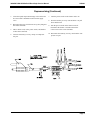
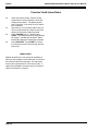
348002K/348012K Manifold Block Style Service Manual
12/2000
○ ○ ○ ○ ○ ○ ○ ○ ○ ○ ○ ○ ○ ○ ○ ○ ○ ○ ○ ○ ○ ○ ○ ○ ○ ○ ○ ○ ○ ○ ○ ○ ○ ○ ○ ○ ○ ○ ○ ○ ○ ○ ○ ○ ○ ○ ○ ○ ○ ○ ○ ○ ○ ○ ○ ○ ○ ○ ○ ○ ○ ○ ○ ○ ○ ○ ○ ○ ○ ○ ○ ○ ○ ○ ○ ○
Service
Manual
348002K/348012K
Manifold Block Style
Recovery/Recycling/Recharging Unit
For R-12 or R-134a Only
TABLE OF CONTENTS:
Theory of Operation and Safety Precautions ........................ 2
Depressurizing the Unit ......................................................... 2
Component Descriptions ..................................................... 4-6
Flow Diagram ......................................................................... 7
348002K Components ............................................................. 8
Pictorial Views ................................................................... 9-10
Plumbing Diagram .......................................................... 12-13
Wiring Diagram (110 volt) .............................................. 14-16
Wiring Schematic (110 volt) ............................................ 17-18
Wiring Diagram (220 volt) .............................................. 19-21
Wiring Schematic (220 volt) ............................................ 22-23
Troubleshooting ............................................................... 24-26
Diagnostic & Function Modes ......................................... 27-28
Function Test ................................................................... 29-30
Labor Rates ........................................................................... 30
Page 1
12/2000
348002K/348012K Manifold Block Style Service Manual
Theory of Operation and Safety Precautions
The 348002K recovery, recycling, evacuation and recharging unit is designed for R-12 and R-134a refrigerant. This
unit is UL approved and meet SAE J1991, SAE J2210, and
SAE J2099 standards.
6.
When the unit shuts off press the menu button then
scroll down to Recycle and start this process. Allow the
unit to pull down and shut off.
7.
When the unit is done recycling close the vapor valve
on the ISV.
8.
Connect a recovery unit up to compressor test port.
9.
Push the menu button then scroll down until change
defaults is displayed Then push 8, 7, 8, 7 and then
enter. Scroll down to step test, then push start.
Depressurizing Unit
Operational
NOTE: If you have to remove any lines or components from
the high side of unit, do so very carefully as there is no
way to recover the refrigerant from the high side.
1.
Disconnect the high and low side service hoses from
vehicle, on 134A units' make sure the coupler valves
are closed.
2.
Open the filter access door and remove the ISV access
panel.
3.
Close the Liquid and Air Purge valve on the ISV. Do
not shut the Vapor Valve. If a source tank is installed on
unit close the supply valve.
4.
Turn the main power switch on and then start a recover.
Allow the unit to pull down and shut off.
5.
When the unit shuts off press the menu button then
scroll down to tank fill and start this process. Allow
the unit to pull down and shut off.
11. Start the second recovery unit and allow it to finish
removing the rest of the refrigerant from the low side
and the compressor return oil separator of the recovery
unit to be repaired.
Depressurizing Unit
Non-Operational
1.
Disconnect the high and low side service hoses from
vehicle, on 134A units’ make sure the coupler valves
are closed.
2.
Open the filter access door and remove the ISV access
panel.
WARNING
Always wear safety goggles when working with refrigerants. Contact with refrigerant
can cause eye injury. Disconnect lines and hoses with extreme caution! Pressurized
refrigerant may be present in lines and hoses. Always point lines and hoses away
from you and anyone nearby.
Always unplug the station from the power source before removing any of the shrouding or beginning any service work.
To order parts, please FAX your order to 1-800-222-7805.
All service related questions should be directed to Robinair Inside Sales and Service
at 1-800-822-5561.
Page 2
348002K/348012K Manifold Block Style Service Manual
12/2000
Depressurizing (Continued)
3.
.
4.
Close the Liquid, Vapor and Air Purge valves on the ISV.
If a source tank is installed on unit close the supply
valve
Disconnect the wires off of the Recovery, Recycling and
Oil-return Solenoids.
5.
Take a cheater cord, with a power switch, and attach it
to these three solenoids.
6.
Connect an auxiliary recovery unit up to compressor
test port.
7.
Turn the power switch on the cheater cord to on.
8.
Start the auxiliary recovery unit and allow it to pull
down and shut off.
9. Turn the power switch on the cheater cord off.
Disconnect the cheater cord and reconnect the
correct wires to the correct solenoids.
10. Disconnect the auxiliary recovery unit from the compressor test port.
Page 3
12/2000
348002K/348012K Manifold Block Style Service Manual
Component Descriptions
110-volt/220-volt
1.
RA19545/RA19 – MANIFOLD ASSEMBLY
•
RA19491/RA19492 – Replacement solenoids coils.
2.
RA19258 – VACUUM SOLENOID – Normally closed
electrical switch that when energized allows a vacuum
to be pulled from the A/C system being serviced.
3.
RA19258 – RECOVERY SOLENOID – Normally
closed electrical switch that when energized allow the
refrigerant to be removed form the A/C system being
serviced.
4.
5.
6.
7.
8.
9.
RA19258 – CHARGE SOLENOID – Normally closed
electrical switch that when energized allows the A/C
system to be refilled with new or recycled refrigerant.
RA19258 – RECYCLE SOLENOID – Normally
closed electrical switch that when energized allows
refrigerant to be ran in a loop through the recovery
filter.
RA19258 – EQUALIZATION SOLENOID – Normally closed electrical switch that when energized
allows the oil in the compressor oil separator to be
returned to the compressor.
RA19529 – EXPANSION VALVE - Controls the flow
of refrigerant into the inlet oil separator to keep it from
being flooded with refrigerant.
RA18752 – VACUUM SWITCH – Normally closed
switch that opens at 13-inhg and stops the recovery
process.
RA19429 – VACUUM PROTECTION SWITCH –
Normally open switch 25+ psi and opens at 10 psi. If
the switch is closed it will not allow the vacuum pump
to start. This is indicated by a U-HI message. Also will
stop you from recovering an A/C system with a possible
leak in it, indicated by a CH-P message.
10. RA19427/RA19763 (25-bar TUV approved) – HIGH
PRESSURE SWITCH – Normally closed between
connections 1 & 3 during normal operations. When the
pressure reaches 435 psi +/- 10 psi the switch will then
close the connections.
Page 4
11. RECOVERY CHECK VALVE – Stops refrigerant
from flowing back out the unit after a recovery is
completed and during the vacuum recycle process.
12. 34724 – RECOVERY FILTER – Removes moisture
from the refrigerant being recovered from the A/C
system.
13. INLET OIL SEPARATOR – Removes the oil out of
the refrigerant being recovered from the A/C system.
14. COMPRESSOR OIL SEPARATOR – Removes the
compressor oil from the refrigerant that is leaving the
compressor.
15. RA19743/RA19595 – R134A, AIR PURGE – Removes excessive air from the recovery tank.
16. RA19744/RA19770 – R12 AIR PURGE – Removes
excessive air from the recovery tank.
17. RA19596 – TRANSFORMER – Takes line voltage
and steps it down to 12 volts.
18. RA17282/RA17324 – RELAY (VACUUM PUMP) –
Electrically controlled switch that when energized will
start the compressor.
19. RA17282/RA17324 – RELAY (R134A COMPRESSOR) – Electrically controlled switch that when
energized will start the compressor.
20. RA17282/RA17324 – RELAY R12 COMPRESSOR)
– Electrically controlled switch that when energized
will start the compressor.
21. RA19047 –VACUUM RECEPTACLE – Supplies
power to the vacuum pump.
22. RA19603 – SCALE (R134A)– Electronic strain gauge
that sends a signal up to the circuit board to display the
.
amount of weight in the tank.
348002K/348012K Manifold Block Style Service Manual
12/2000
Component Descriptions
23. RA19603 – SCALE (R12)– Electronic strain gauge
that sends a signal up to the circuit board to display the
.
amount of weight in the tank.
24. RA17416/RA17516 – FAN – Cool the compressor
electrical components so that it does not shut down on
thermal overload.
25. RA17416/RA17516 – FAN – Cool the compressor
electrical components so that it does not shut down on
thermal overload.
26. RA19748/RA19762 – COMPRESSOR (R12) – Moves
the refrigerant from the A/C system being serviced to
the storage tank on the unit.
27. RA19748/RA19762 – COMPRESSOR (R134A)–
Removes the refrigerant from the A/C system being
serviced to the storage tank on unit.
28. RA15425/15630 – VACUUM PUMP– Two stage 6 cfm
rotary pump designed to pull moisture and air from an
A/C system
29. RA19612/RA19764 – ISV (R134A) – Storage vessel
that the recovered and recycled refrigerant is stored.
30. RA19612/RA19764 – ISV (R12) – Storage vessel that
the recovered and recycled refrigerant is stored.
31. RA19181 – IEC RECEPTACLE – Power cord plugs
into this and supplies power to the main power switch.
32. RA17548 (3-AMP)/RA19760 (1.5-AMP) CIRCUIT
BREAKER – Protects the power transformer.
33. RA17549 (15-AMP)/RA9759 (7.5-AMP) CIRCUIT
BREAKER – Protects unit from drawing too much
amperage and shorting electrical components out.
34. 122238 – OIL INJECTOR ASSEMBLY – Allows the
new oil to be injected into the A/C system to replace the
oil that was removed during the recovery process.
35. RA19291 – REPLACEMENT BALL VALVE (90) –
When open, and a vacuum is present, this will allow the
oil to be injected.
36. 122917 - PNEUMATIC CONNECTION
37. 122024 - OIL INJECTION BRACKET
38. 110135 - STAR WASHER
39. 121449 - OIL BOTTLE CAP
40. 115112 - PNEUMATIC CONNECTION
41. 117664 - OIL INJECTION DIP TUBE
42. RA19291 - 8oz OIL INJECTION BOTTLE
43. 122124 - OIL DRAIN ASSEMBLY - After recovery is
completed, assembly will automatically drain the oil
that was removed from the A/C system during recovery.
44. 115642 - 12oz OIL DRAIN BOTTLE
45. 113564 - JAM NUT
46. 117327 - BULKHEAD FITTING
47. 122950 - "T" FITTING
48. 122237 - .042 ORIFICE FITTING
49. RA19006/RA19008 - REPLACEMENT SOLENOIDAutomatically opens after recovery and allows the oil to
drain. Will shut off automatically when the oil drain
switch reaches 9-psi.
• RA19258 SOLENOID REBUILD KIT
• RA19491/RA19492 REPLACEMENT COIL
50. RA19282 CHECK VALVE - Stop the unit from
pulling air in through the oil drain during the recovery
process through the upper chamber during recycling.
51. 111858 - "T" FITTING
52. 119994 ELBOW
53. RA19672 - OIL DRAIN SWITCH - When recovery is
completed will pressurize the low side to 16-psi then
open the oil drain solenoid and allow the oil to drain.
Will shut the oil drain solenoid when the pressure on
the low side reaches 9-psi.
54. 122950 -PNEUMATIC ELBOW
55. 122219 - OIL INJECTION BRACKET
Page 5
12/2000
348002K/348012K Manifold Block Style Service Manual
Component Descriptions
56. 122987 CONTROL PANEL ASSEMBLY- Contains
the gauges, switches, control board and manifolds to
operate the unit.
57. RA19741 R12 LOW SIDE GAUGE - Allows the
pressures on the low side of the vehicle being service to
be monitored.
58. RA19742 R12 HIGH SIDE GAUGE - Allows the
pressures on the high side of the vehicle being service
to be monitored.
59. 117684 REFRIGERANT SELECTOR SWITCH Allows the unit to be switched from R12 to R134a.
60. RA19614 R134a LOW SIDE GAUGE - Allows the
pressures on the low side of the vehicle being service to
be monitored.
61. RA19613 R134a HIGH SIDE GAUGE - Allows the
pressure on the high side of the vehicle being service to
be monitored.
111161 ELBOW - Connect to the back of gauges.
121771 PNEUMATIC FITTING - Connects the
tubing from the gauge to the control panel manifold
valves.
62. 123210 CONTROL PANEL DECAL
63. RA19740 MAIN CIRCUIT BOARD - Controls the
function of the unit.
•RA19673 DAUGHTER BOARD (UL BOARD)
64. 121943 KEY PAD - Allows the user to input information into the main circuit board.
72. 117327 1/4" FLARE BULKHEAD (R12 MANIFOLD)
73. 111161 ELBOW
74. 122357 LOW SIDE HOSE - Provides a connection
between the low side service hose and the control panel
manifold.
75. 122618 INLET HOSE - Provides a connection between
the control panel manifold and the main manifold
block.
76. 122356 HIGH SIDE HOSE - Provides a connection
between the high side service hose and the control
panel manifold.
77. 122925 PNEUMATIC CONNECTION - Connect the
oil-injector to the control panel manifold.
78. 113025 CHECK VALVE - Stops refrigerant from
entering the oil injectors.
79. 111858 "T"
80. 112870 ELBOW
81. 116420 "T"
82. 107021 SCREEN
83. 122190 PNEUMATIC WHEEL
84. 113160 CASTOR
85. 122875 MANIFOLD BAR ASSEMBLY
HOSES
65. 121845 BEZEL
86. 18190A R-134a Low Side Hose Coupler (blue)
66. RA19343 MAIN POWER SWITCH - Allow the unit
to be turned on and off.
87. 18191A R-134a High Side Hose Coupler (red)
67. 122926 MANIFOLD ASSEMBLY - Allow the units
gauges and the vehicle being service to be isolated from
the rest of the unit.
89. 63096 R-134a High Side Hose
68. 122978 TUBE - Provides a path for charging.
88. 62096 R-134a Low Side Hose
• RA19115 Coupler O-ring repair kit (front)
• 17772 O-ring between coupler and hose
69. 119983 COUPLING
90. 68296A R-12 96" Blue Quick Seal Hose
70. RA19581 PNEUMATIC CONNECTOR - Connects to
the system gauges.
91. 68396A R-12 96" Red Quick Seal Hose
• 18180 Replacement R-12 Quick Seal O-ring
71. 117328 1/2" ACME BULKHEAD (R134A MANIFOLD)
Page 6
348002K/348012K Manifold Block Style Service Manual
12/2000
Flow Diagram
Block Representation
INST 0717
Page 7
12/2000
348002K/348012K Manifold Block Style Service Manual
348002K Components
18
21
34
56
20 19
17
23
22
33
15
16
32
1
1
31
43
12
30
29
24
26
25
84
28
27
83
INST0856
Manifold Block
10
6
7
5
8
4
11
3
9
14
2
12
13
INST0857
Page 8
348002K/348012K Manifold Block Style Service Manual
12/2000
Control Panel
57
59
58
61
60
62
67
67
64
65
66
63
INST0858
Control Panel Manifold
71
71
72
72
73
73
75
74
70
76
77
81
81
82
78
79
69
68
80
85
INST0861
Page 9
12/2000
348002K/348012K Manifold Block Style Service Manual
Oil Injectors
36
35
37
38
36
39
40
41
INST0860
42
Oil Drain
52
53
48
51
53
50
49
54
48
55
47
46
38
39
45
44
INST0859
Page 10
348002K/348012K Manifold Block Style Service Manual
12/2000
Compressor Specifications
RA19458 100V-110V COMPRESSOR
RA19457 220V COMPRESSOR
COMPRESSOR SPECIFICATIONS:
Suction and Discharge Pressure Test:
1/3 hp hermetic (piston type)
compressor
1. Disconnect all fittings from the unit.
Oil Capacity:
10 ounces (296 milliliters)
Oil Type:
150 viscosity POE refrigeration oil
Voltage:
100-110V units use a RA19458
220V units use a RA19457
3. Install a low side gauge on the suction fitting. Note:
The fittings used on these compressors require an
o-ring fitting to seal, use a 120063 hose (1/4" flare
o-ring X 1/2" ACME Q.S.) with an R-134a manifold
set.
Amperage:
4-6 running amperage (100-110V)
20-25 locked rotor amperage
3-4.5 running amperage (220V)
16-19 locked rotor amperage
Type:
2. Cap the intake fitting.
4. Verify that the discharge fitting is unobstructed.
1. Depressurize the unit.
5. Start the compressor and monitor the suction
readings. The compressor should pull a 25” (-.85
bar) vacuum. If the compressor has weak suction,
check the oil level and add if necessary. If the oil
level is okay or oil was added with no improvement,
replace the compressor.
2. Remove the compressor from the unit and place
on a flat surface.
6. Disconnect the low side gauge from the suction
fitting.
3. Tilt the compressor 30° (see figure above). At this
angle, there should be oil in the suction fitting.
7. Install a high pressure gauge on the discharge
fitting. Note: The fittings used on these compressors require an o-ring fitting to seal, use a 120063
hose (1/4" flare o-ring X 1/2" ACME Q.S.) with an
R-134a manifold set.
Checking The Oil
Adding Oil
1. Install a funnel in the suction fitting and pour two
ounces of oil into the funnel.
2. Start the compressor momentarily. Plug the intake
fitting, but leave the discharge fitting open. The
compressor will pull oil from the funnel. Stop the
compressor.
8. Verify that the intake fitting is unobstructed.
9. Start the compressor and monitor the pressure for
four minutes. If the pressure doesn’t reach at least
350 psi (24 bar), replace the compressor.
3. Check the oil level. If still low, add two ounces of
oil at a time until the proper level is achieved.
Page 11
12/2000
348002K/348012K Manifold Block Style Service Manual
Plumbing Diagram
100V-110V
INST0862
Page 12
348002K/348012K Manifold Block Style Service Manual
12/2000
Plumbing Diagram
100V-110V
INST0868
Page 13
12/2000
348002K/348012K Manifold Block Style Service Manual
Wiring Diagram
100V-110V
INST0864
Page 14
348002K/348012K Manifold Block Style Service Manual
12/2000
Wiring Diagram
100V-110V
INST0863
Page 15
12/2000
348002K/348012K Manifold Block Style Service Manual
Wiring Diagram
100V-110V
RA19740
RA19673
INST0865
Page 16
348002K/348012K Manifold Block Style Service Manual
12/2000
Wire Schematic
110v-110v
INST0866
Page 17
12/2000
348002K/348012K Manifold Block Style Service Manual
Wire Schematic
110v-110v
INST0867
Page 18
348002K/348012K Manifold Block Style Service Manual
12/2000
Wiring Diagram
220V
INST0864
Page 19
12/2000
348002K/348012K Manifold Block Style Service Manual
Wiring Diagram
220V
INST0867
Page 20
348002K/348012K Manifold Block Style Service Manual
12/2000
Wiring Diagram
220V
RA19740
RA19673
INST0867
Page 21
12/2000
348002K/348012K Manifold Block Style Service Manual
Wire Schematic
220V
INST0870
Page 22
348002K/348012K Manifold Block Style Service Manual
12/2000
Wire Schematic
220V
INST0871
Page 23
12/2000
348002K/348012K Manifold Block Style Service Manual
Troubleshooting
WILL NOT RECOVER:
Compressor runs:
1. If the unit is being run through an extension cord,
eliminate its use.
2. Disconnect the high and low side hoses from the
vehicle with the gauge valves open. If the pressure
on the gauges drops while the display shows
clearing, check voltage to the recovery solenoid. If
voltage is present, replace the main board. If
voltage is not present, the recovery solenoid may
need to be rebuilt.
3. Check the oil drain assembly. Verify that it is closed
and not bleeding through.
4. Check the pressure at the service port. If there is a
vacuum deeper than 15” (-.51 bar), test the vacuum
sensor for continuity. If there is no continuity
replace the main board.
5. Close the ESV liquid valve. If the unit did not come
out of clearing, but now does and completes a
recovery, rebuild the recycle solenoid. If the unit
came out of clearing, but would not complete a
recovery and now does, rebuild the charging
solenoid. Check for voltage at the recycling and
charging solenoids. If the solenoids are receiving
power, verify proper wire connection and replace
the main board if necessary.
6. Inspect the filter for flow obstructions and check for
leaks around the gasket area. When installing
gaskets, be sure to lubricate them with vacuum
grease or refrigerant oil.
7. Verify that the equalization solenoid is not receiving
power. NOTE: The equalization solenoid is a
normally closed solenoid. If it is receiving power,
check for proper wire connection and proper
installation. If the wires are connected to their
corresponding pins, replace the main board.
8. Check the equalization solenoid for bleed through to
the suction side of the compressor. Rebuild the
solenoid if it is bleeding through.
9. Check the compressor suction and discharge
pressures. Replace the compressor as necessary.
Compressor does not run:
1. If the unit is being run on an extension cord, eliminate its use.
2. If the display does not respond to keypad commands, verify that the keypad is plugged in.
3. If there is still no response replace the keypad. If
the keypad is functioning properly, you will hear a
tone when you press a key.
Page 24
4. If the keypad is functioning properly, verify proper
wire harness connections to the board and the
compressor relays.
5. Check for 110 volts to the coil of the compressor
relay (pins 0 & 1 ). If there is no voltage, check the
wires from the main board to the compressor relays
for continuity. If they have continuity replace the
main board.
6. If the compressor relays are receiving 110 volts to
the coil, check for voltage from the #4 contact of the
relay board. If there is poor compressor voltage,
replace the relay.
7. If voltage is present at the compressor, jumper the
thermal overload. If the compressor runs, check the
compressor amp draw. If it is drawing higher than 6
amps or not running, replace the compressor. If the
compressor is cool and drawing low amperage,
replace the thermal overload.
Display Reads FULL:
1. Check the ESV weight and replace if the ESV is full.
2. Check the scale calibration. The display should read
2.5 pounds with a 20-pound weight sitting on the
scale. If the scale is out of calibration calibrate.
3. The UL circuit must be reset whenever the scale is
calibrated. The UL pot for the R-12 side is located
on the main board. The UL pot for the R-134a pot is
on the smaller daughter board.
4. Replace the scale if previous attempts fail.
5. Replace the main board if replacing the scale does
not correct the problem.
WILL NOT RECOVER (Continued):
Display reads HI-P:
1. Check to be sure all of the ESV valves are open,
“the vapor, air-purge and the liquid.”
2. Check the ISV pressure. If the pressure exceeds
435 psi (30 bar ), release the pressure down to 200
psi.
3. If the ESV does not have an excessive amount of
pressure you will need to check the high-pressure
switch for continuity, between pins 1 & 2. If pins 1 &
2 have continuity, there may be an obstruction in the
discharge line.
4. Inspect the discharge line and check valve for
obstructions if both of these are clear and free of
obstructions replace the high pressure switch.
348002K/348012K Manifold Block Style Service Manual
12/2000
Troubleshooting
Display Reads SCALE ERROR:
Unit will not evacuate, vacuum pump runs:
1. Remove all weight from the scale.
2. Check the scale calibration by placing 20 pounds on
the empty scale. The display should read 2.5
pounds. Calibrate if necessary.
3. Check the scale cable to be sure it is properly
connected to the board. (NOTE: The R12 scale
plugs into the main board, the R134a scale plugs
into the small daughter board.)
4. Replace scale if previous attempts fail.
5. Replace the main board if replacing the scale does
not correct the problem.
1. If the unit is being run through an extension cord,
eliminate its use.
2. Verify that the manifold gauge valves are open.
3. Check the low side gauge for proper operation and
calibration.
4. Be sure the plastic vacuum line is snug at all of the
connection points.
5. Check for proper vacuum oil level in the vacuum
pump sight glass (oil should be in the middle of the
sight glass while the pump is running). Fill vacuum
pump if needed.
6. Check for suction at the inlet of the pump. If there
is none replace the pump.
7. Check for voltage to the vacuum solenoid. If there
is 110 volts present, rebuild the solenoid. If there is
not 110 volts at the vacuum solenoid check the
wires and the connection on the board. This unit
also has a free air solenoid mounted on the vacuum
pump. This solenoid should receive 110 volts during
the vacuum process. If the solenoid does not
receive 110 volts check the wire connections and
for continuity. If the wires have continuity check to
make sure the 3-way solenoid is not bleeding
through. If the solenoid bleeds through rebuild
solenoid.
Display Reads DRAINING OIL:
1. Verify all ESV and manifold valves are open.
2. Check for pressure on the manifold gauges. If there
is no positive pressure, connect to a vapor supply
source and attempt recovery again.
3. Connect a pressure gauge to the service port on
the oil return line. If there is no positive pressure on
in the low side of the unit, but there is still pressure
on the manifold gauges, verify the inlet check valve
is opening, verify the recovery solenoid is receiving
110 volts and opening and allowing flow. If the
solenoid is receiving 110 volts clean and repair the
solenoid. If the solenoid is not receiving 110 volts
check the wires for continuity. If the wires have
continuity replace the main board.
4. If there is positive pressure in the low side of the
unit, check for loose wires on the vacuum switch.
Check the vacuum sensor for continuity and replace
if it has none.
Display Reads LOW SYSTEM PRESSURE:
1. If there is less than 25 psi at the inlet, and the
vacuum pump protection switch has continuity,
press start to continue recovery. If the unit does not
continue with the recovery process, test the keypad
for proper function. If the keypad works properly,
replace the main board.
2. If there is more than 25 psi at the inlet, check the
vacuum pump protection switch for continuity and if
it has none replace the switch. If the switch has
continuity, check the wires for proper connection to
the main board and replace either component as
necessary.
Display reads HIGH SYSTEM PRESSURE:
1. If there is more than 25 psi at the inlet, recover
before evacuating. If pressure continues to rise on
the gauges after recovery inspect the inlet check
valve.
2. If there is less than 25 psi at the inlet, check the
vacuum pump protection switch for continuity. If the
switch has continuity replace the switch. If the
switch does not have continuity check the wires and
replace the switch as necessary.
Vacuum pump does dot run:
1. If the unit is being run through an extension cord
eliminate its use.
2. Verify the vacuum pump is plugged into the receptacle.
3. Check the voltage at the vacuum pump receptacle.
If there is 110 volts at the receptacle, be sure the
pump is not over filled with oil (if the pump is over
full drain pump and refill to proper level). If the
pump will still not start replace the pump.
Page 25
12/2000
348002K/348012K Manifold Block Style Service Manual
Troubleshooting
4. If there is not 110 volts present at the vacuum pump
receptacle, check the wire connections to the
vacuum pump relay. Pins 1 & 0 should have
voltage. If the relay has power replace the relay. If
the relay does not have power, check the wires for
continuity to the board. If wires check out replace
the board.
Will not Recycle:
1. Check that all ESV hoses are properly installed and
ESV valves are completely open.
2. Verify that there is a minimum of 10 pounds of
refrigerant in the tank.
3. Verify that the oil drain assembly is closed and not
bleeding through.
4. Install the low side of a manifold gauge set to the
service port on the compressor oil return line to
verify that the expansion valve is set between 35
and 40psi. Adjust the expansion valve if necessary.
5. If the low side of the unit is in a vacuum, and the
expansion valve does not adjust to allow flow,
replace the expansion valve.
6. Check the filter for flow obstructions.
7. Verify that the equalization solenoid is not receiving
power. If the equalization solenoid is receiving
power, replace the main board. If the equalization
solenoid is not receiving power, check the solenoid
for bleed through and repair as necessary.
8. If the compressor is not running, verify that voltage
is being supplied to the compressor. If it is not
receiving power, check the wiring to the compressor
relay and check the compressor relay for proper
operation.
9. If the compressor is receiving voltage, but is not
running, check the compressor start components
and check the amp draw of the compressor. Replace the compressor as necessary.
10. If the compressor is running, check the compressor
suction and the discharge pressures as well as the
oil level.
Will not perform an air purge:
NOTE: The air purge solenoid does not receive
power for the first 30 seconds of recycling, and will
on receive power for a maximum of 10 minutes.
Page 26
1. Verify that the ESV tank has an excess amount of
pressure in it. Check the pressure in the ESV in
relationship to the temperature of the refrigerant. The
air purge device requires at least 7 psi of excess
pressure to open.
2. If excess air pressure is confirmed, verify that all
ESV hoses are properly installed.
3. While running in the Vacuum Mode for at least three
minutes, verify that the air purge solenoid is receiving 110 volts. If the solenoid is not receiving 110
volts check the wires to the board.
4. If the air purge solenoid is receiving 110 volts,
rebuild the solenoid or replace the coil if necessary.
5. If the air purge solenoid is operating properly,
replace the air purge device.
Will Not Charge:
NOTE: There is no component that pumps in
refrigerant into a system during the charge process.
The refrigerant flows into the system by way of
pressure transfer. If the system is not in a vacuum,
this unit will not charge.
1. If the unit is being run through an extension cord,
eliminate its use.
2. Check that all ESV hoses are properly installed and
the valves are open.
3. Verify that the manifold valves are in the “oil inject /
charge” position.
4. If LOW REFRIGERANT is on the display, verify that
there is at least 10 pounds of refrigerant in the ESV.
If there is refrigerant in the ESV, check the scale
calibration and calibrate as necessary.
5. Verify that the board has accepted the programmed
amount. Test operation of the keypad for proper
function.
6. Be sure the scale is unobstructed.
7. Check the charge solenoid to insure it is receiving
110 volts. If there is no voltage, check the wires to
the board for continuity and proper connection. If
the wires have continuity replace the board. If the
solenoid is receiving 110 volts rebuild the solenoid,
or replace the coil if necessary.
8. If a partial charge occurs, close the high side valve,
start the vehicle and pull the remaining charge on
the low side of the system. When the charge has
been pulled from the ESV, the charging solenoid
should close, preventing a possible over charge.
348002K/348012K Manifold Block Style Service Manual
12/2000
Diagnostic & Function Modes
NOTE: If the unit that you are servicing has the board with version 1.6 the board will need to be
updated to version 1.12
The diagnostic and function modes are accessed by pressing the MENU key and using the UP and DOWN
arrows to scroll through the menu.
LANGUAGE SELECTION
Allows the user to change the default language they will work in. Press the
ENTER key to access this feature. Use the UP and DOWN arrows to select the
language and hit the ENTER key to save to the board.
CHANGE FILTER
This feature allows the user to change the filter drier on his unit.
FILTER WEIGHT
Displays the amount of refrigerant that has passed through the filter during
recovery since the last time the filter was changed or the amount was reset. To
reset the weight without doing a filter change press ENTER then press 8-7-8-7.
The filter weight should reset to zero. Press ENTER to exit this mode.
SELECT AUTO-RESTART
This function allows the user to automatically restart recover if there is a rise in
pressure in the system. Press ENTER to access this mode and use the UP or
DOWN arrows to select. Press ENTER to exit.
MEASUREMENT UNITS
Allows the user to select pounds or kilograms. Press ENTER to access, use UP
or DOWN arrows to select, press ENTER to exit.
CHANGE VAC-PUMP OIL
Allows the user to change the vacuum pump oil and resets the “OIL” message.
Press ENTER to access, follow prompts. The vacuum pump will run for 2
minutes. You will then be prompted to change the vacuum pump oil. Add 5
ounces of oil to the vacuum pump. Fill vacuum pump to the middle of the sight
glass with pump running. Press STOP to exit.
TANK FILL
Allows the user to fill his ESV. Press ENTER to access this function. Follow on
screen prompts. Connect low side hose to source tank, open low side manifold
valve, press START. Unit shuts off automatically when tank reaches fifteen
pounds.
VACUUM OIL TIME
Will show the user how long the vacuum pump has run since the last oil change.
Press Enter to access the function. Press 8-7-8-7 to reset the time. Press
ENTER to store to the board.
INSTALLATION ROUTINE
Is used during original set up of the unit. Follow the on screen prompts.
SELECT PROMPTS
CHANGE DEFAULTS
Allows the user to choose between basic and advanced operation. Press ENTER to access. Press UP or DOWN arrow to select.
Is a function installed for service purposes. It is accessed by typing in 8-7-8-7 at
the change defaults prompt, then press the ENTER key. There are five subroutines in this menu. The routines are as follows.
VACUUM TIME DEFAULT
Press ENTER to access, type in new default time, press ENTER to store.
Page 27
12/2000
348002K/348012K Manifold Block Style Service Manual
Diagnostic & Function Modes
CALIBRATE SCALE
Press ENTER to access. ( NOTE: The side that is selected is the only side that
can be calibrated.) Key in the date starting with month followed by day then year.
Remove all weight from the scale. Press ENTER. Press ENTER to communicate the 20 pound weight to the board. Place a 20 pound weight on the scale
and press ENTER to store to the board. (NOTE. You must use a known 20
pound weight.)
CALIBRATE UL CIRCUIT
Press ENTER to access. Remove all weight from both scales. Place 45 pounds
on the R-12 scale. Turn the potentiometer located on the main board until the
display reads set. Remove 1 pound. The display should go to CLR. Place 43
pounds on the R-134a scale. Turn the potentiometer on the daughter board until
the display reads set. Remove one pound. The display should read CLR. Press
ENTER to exit.
STEP TEST
Press ENTER to access. Use the UP and DOWN arrows to scroll through all of
the outputs. Press START to turn on the outputs. Press STOP to turn outputs
off. Press ENTER to exit. (NOTE: All outputs should be checked during the
function test.)
SET TANK TARE
Press ENTER to access. Type in the weight of the tank. The default weight is
17.50 pounds. Press ENTER to exit.
Press 0 to turn off any solenoid or relay engaged. In this mode two components
cannot be energized at the same time; selection of a new component will automatically turn off one that is still active. Press SHIFT/RESET to exit the step test and
return to normal operation.
Page 28
348002K/348012K Manifold Block Style Service Manual
12/2000
Function Test
NOTE: The ESV must have at least 10 pounds of
refrigerant in it to perform this test. This test needs to
be performed on both the R-12 and R-134a sides of the
unit.
1.
2.
3.
4.
5.
6.
7.
8.
9.
10.
11.
12.
13.
14.
Turn on the Main Power switch.
Pressurize the high and the low side hoses
with refrigerant.
Close the low side manifold valve.
Open the high side manifold valve.
Attach a hand held manifold to the service port
on the compressor oil return line. Verify that
the valves on the hand held manifold set are
closed.
Verify that all ISV hoses are connected to the
ISV in the correct order.
Open all valves on the ISV.
Press RECOVER. The display will prompt you
to connect hoses and press START. After
pressing start the display will read CLEARING.
The gauge will pull down to 13” of vacuum.
Upon reaching a 13” vacuum, the recovery
solenoid will automatically open and the gauge
should repressurize. The compressor will now
pull both of the unit gauges into a 13” vacuum
and the compressor should shut off and the
display will go to DRAINING OIL.
The gauge will build pressure and a pressure
transfer should be heard. If no rise occurs the
equalization solenoid should be inspected for
obstruction and the proper voltage.
Verify that the unit goes to RECOVERY
COMPLETE after the unit finishes with DRAINING OIL. If the display stays in DRAINING
OIL, check the oil drain switch located on the
oil drain assembly. (NOTE: The oil drain
switch is a 9 psi to 16 psi switch, When the
switch sees 16 psi it opens and remains open
until the pressure drops to 9 psi or below.)
Press the STOP key to return to main menu.
Press VACUUM. Press START. Press ENTER. The vacuum pump will start and the
display will count down from 15:00 minutes.
After 6 seconds the compressor, recycle
solenoid, and the vacuum solenoid will receive
110 volts and open. The control panel gauges
will pull into a deep vacuum and the unit will
begin to recycle refrigerant.
15.
16.
17.
18.
19.
20.
21.
22.
23.
24.
25.
26.
27.
28.
29.
30.
31.
After 30 seconds the air purge solenoid will
receive 110 volts for 10 minutes. Once the air
purge solenoid opens, the air purge device
receives pressure form the ISV. If the air purge
device senses a difference of over 7 psi the air
purge device will purge the pressure down to 3
psi difference.
After 10 minutes the hand held gauge should
read between 30 to 40 psi. Adjust the expansion valve to comply with these specifications if
necessary.
Leak test all the internal and external lines and
fittings while the unit finishes recycling.
After 15:00 minutes the vacuum procedure is
complete and shuts off automatically. Press
STOP to exit to the main menu.
Disconnect from the service port.
The low side manifold gauge on the control
panel should hold a vacuum.
Close the vapor valve on the ISV.
Disconnect the vapor hose from the ISV
Attach the vapor hose to the high side on a
hand held manifold set making sure the high
side valve is closed. You will need to make up
a fitting that is o-ring on one end and quarter
flare on the other. Connect the center port of
the hand held manifold to the vapor port on the
ISV.
Press VACUUM. Press START. Press ENTER.
The unit will start go into vacuum. 6 seconds
later it will start a recycle and the high side
manifold will start to increase pressure.
The unit will shut off when the high side
manifold reaches 435 psi. The display will read
HIGH PRESSURE RESETTING.
The pressure on the high side gauge should
hold above 420 psi for at least three minutes.
If the pressure drops instantly or bleeds off
steadily, replace the discharge check valve.
After checking for pressure loss, slowly open
the high side manifold valve to release the
pressure into the ISV.
Once pressure is equalized, close the vapor
valve on the ISV and disconnect the hand held
manifold from the vapor hose and the ISV.
Reconnect the vapor hose to the ISV.
Open the vapor valve on the ISV.
Press START to clear the HIGH PRESSURE
RESETTING message from the display.
Page 29
12/2000
348002K/348012K Manifold Block Style Service Manual
Function Test & Labor Rates
32.
33.
34.
35.
Check the scale accuracy. Remove all the
weight from the scale and place a 20 pound
weight on the platform. The display should
read 2.5 pounds. If the scale is out of calibration, recalibrate.
Check the UL circuit for both sides of the unit.
The R-12 side needs 45 pounds on the scale
and the R-134a scale needs 43 pounds.
Press CHARGE. Key in .1 pound. Press
START. The charge solenoid is energized and
will charge .1 pounds into the hoses. When
finished the display will read charge complete.
Press RECOVER. Press START to remove
the remaining pressure from the high and low
side hoses.
LABOR RATES
Robinair authorizes a 2 hour charge to troubleshoot,
leak test, and complete a full function test on units that
are covered under factory warranty. The authorized
time for parts replacement is 15 minutes per part. If
repairs are estimated to exceed 3 hours, prior authorization from Robinair is required.
Page 30