1
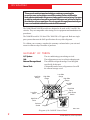
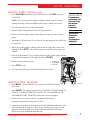
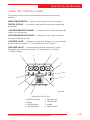
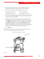
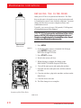
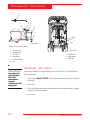
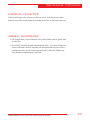
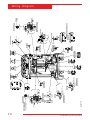
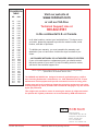
○ ○ ○ ○ ○ ○ ○ ○ ○ ○ ○ ○ ○ ○ ○ ○ ○ ○ ○ ○ ○ ○ ○ ○ ○ ○ ○ ○ ○ ○ ○ ○ ○ ○ ○ ○ ○ ○ ○ ○ ○ ○ ○ ○ ○ ○ ○ ○ ○ ○ ○ ○ ○ ○ ○ ○ ○ ○ ○ ○ ○ ○ ○ ○ ○ ○ ○ ○ ○ ○ ○ ○ ○ ○ ○ ○ ○ ○
Operating Manual, Model 348002K/348012K
Recovery/Recycling/Recharging Unit
For R-12 and R-134a Refrigerants ................................. 1
Series: 348002K/348012K
Refrigerant Recovery,
Recycling and Recharging Station
Refrigerants: R-12 and R-134a
WARNING
PRESSURIZED TANK CONTAINS LIQUID REFRIGERANT. OVERFILLING OF THE TANK MAY CAUSE VIOLENT
EXPLOSION AND POSSIBLE INJURY OR DEATH. Refer to the instruction manual for tank specifications and ordering
information. Do not recover refrigerants into a non-refillable storage container! Federal regulations require refrigerant to
be transported only in containers meeting DOT spec. 4BW or DOT spec. 4BA.
ALL HOSES MAY CONTAIN LIQUID REFRIGERANT UNDER PRESSURE. Contact with refrigerant may cause injury.
Wear proper protective equipment, including safety goggles. Disconnect hoses with extreme caution.
HIGH VOLTAGE ELECTRICITY INSIDE PANELS. RISK OF ELECTRICAL SHOCK. Disconnect power before servicing
unit. Refer to the instruction manual.
TO REDUCE THE RISK OF FIRE, avoid the use of an extension cord because the
extension cord may overheat. However, if you must use an extension cord, use No. 14 AWG at the minimum and as
short as possible. Do not use this equipment in the vicinity of spilled or open containers of gasoline or other flammable
substances.
Use this equipment in locations with mechanical ventilation that provides at least four air changes per hour or locate the
equipment at least 18 inches above the floor.
Make certain all safety devices are functioning properly before operating the unit. Before operating, read and follow the
instructions and warnings in this manual.
CAUTION: SHOULD BE OPERATED BY QUALIFIED PERSONNEL. Operator must be familiar with air conditioning
and refrigeration systems, refrigerants and the dangers of pressurized components.
Use only with R-12 or R-134a. This equipment is not designed for any other purpose than recovering, recycling
or recharging refrigerants! Do not mix refrigerant types!
ATTENTION!
Ce réservoir sous pression contient du frigorigène liquide. S’il est surchargé, ce réservoir peut exploser et causer des
blessures ou la mort.
ATTENTION. Débrancher avant la maintenance.
ATTENTION. Pour réduire les risques d’incendie, ne pas utiliser de cordon prolongateur de section inférieure à 14 AWG
de facon à éviter la surchauffe du cordon.
ATTENTION. Utiliser seulement du frigorigène R-134a.
OPERATING NOTES
At temperatures exceeding 120oF / 49oC, wait 10 minutes between recovery jobs.
R-12 and R-134a WARNINGS!
Use the Series 348002K/348012K only with R-12 or R-134a! Cross-contamination with other refrigerant types will cause
severe damage to the A/C system and to service tools and equipment. Do not mix refrigerant types through a system or
in the same container!
Avoid breathing A/C refrigerant and lubricant vapor or mist. Exposure may irritate eyes, nose and throat. To remove
R-12 or R-134a from the A/C system, use service equipment certified to meet the requirements of SAE-J2210 (R-12 or
R-134a recycling equipment). If accidental system discharge occurs, ventilate work area before resuming service.
R-12 or HFC-134a service equipment or vehicle A/C systems should not be pressure tested or leak tested with compressed air. Some mixtures of air/HFC-R-12 /R-134a have been shown to be combustible at elevated pressures. These
mixtures are potentially dangerous and may result in fire or explosion causing injury or property damage.
Additional health and safety information may be obtained from refrigerant and lubricant manufacturers.
Table of Contents
Introduction ...................................................................................... 2
Glossary of Terms ............................................................................. 2
Set-UpInstructions ............................................................................. 4
Initial Set-Up ..................................................................................... 4
Preparing the Vacuum Pump ............................................................... 5
OperatingGuidelines ......................................................................... 6
Using the Selection Menu .................................................................... 6
Change Filter .................................................................................... 6
Recycle ............................................................................................. 6
External Storage Vessel (ESV) Refill ...................................................... 7
Vacuum Pump Hours ......................................................................... 8
Drier Recovered Lbs. .......................................................................... 9
Basic/Advanced Prompts.................................................................... 9
Auto Restart ON/OFF ........................................................................ 9
Selecting a Unit (Metric/English) ........................................................ 10
Language Select .............................................................................. 10
Installation Routine/First Fill .............................................................. 10
Using the Control Panel .................................................................... 11
Keypad Functions ............................................................................ 12
OperatingInstructions ...................................................................... 13
Operating Tips ................................................................................ 13
Recovering Refrigerant ..................................................................... 14
Evacuating the A/C System............................................................... 16
Replenishing A/C System Oil ............................................................ 18
Recharging the A/C System .............................................................. 19
MaintenanceInstructions .................................................................. 20
Replacing the Filter-Drier .................................................................. 20
Changing the Vacuum Pump Oil ........................................................ 21
Checking for Leaks ........................................................................... 22
Electrical Protection .......................................................................... 23
General Maintenance....................................................................... 23
ReplacementPartsList(348002K) ...................................................... 24
ReplacementPartsList(348012K) ...................................................... 26
FlowDiagram ................................................................................. 27
WiringDiagram .............................................................................. 28
LimitedWarranty ............................................................................ 29
U.S. Patents: 4,523,897; 4,688,388 Re 33,212; 4,768,347; 4,805,416; 4,809,520; 4,878,356; 4,938,031;
5,005,369; 5,005,375; 5,038,578; 5,042,271; 5,209,653; 5,248,125 Australian Patent: 613,058 Canadian
Patents: 1,311,621; 1,311,622; 2,012,620; 2,026,348 European Patent: 0 315 296 Bl German Patent: 031296
Mexican Patent: 16208 OTHER U.S. AND FOREIGN PATENTS PENDING.
Mfd. by Robinair, SPX Corporation, Montpelier, OH 43543
348002K/348012K Cool-Tech Recovery/Recycling/Recharging Unit
1
Introduction
Thismanualcontainsimportantsafetyproceduresconcerningthe
operation, use, and maintenance of this product. Failure to follow the
instructions contained in this manual may result in serious injury. If you are
unable to understand any of the contents of this manual, please bring it to
the attention of your supervisor. Do not operate this equipment unless you
have read and understood the contents of this manual.
The 348002K and 348012K models are designed to be used on R-12 and R-134a
vehicles. They are compatible with existing service equipment and standard service
procedures.
The 348002K model is UL-listed. The 348012K is CE approved. Both are single
pass systems that meet the SAE specifications for recycled refrigerant.
To validate your warranty, complete the warranty card attached to your unit and
return it within ten days from date of purchase.
GLOSSARY OF TERMS
A/C System
Unit
ExternalStorageVessel
SourceTank
Low Side
Gauge
The air conditioning system being serviced.
The refrigerant recovery/recycling/recharging unit.
The refillable refrigerant storage vessel designed
specifically for this unit.
A disposable tank of new refrigerant used to refill
the external storage vessel.
High Side
Gauge
Low Side
Gauge
High Side
Gauge
Low Side
Valve
High Side
Valve
Low Side
Valve
Main Power
Switch
High Side
Valve
Selector
Switch
Keypad
INST 0706
Diagram of the 348002K Control Panel
2
© 2000 Robinair, SPX Corporation
Set-Up Instructions
8
2
10
4
Diagram of Unit’s Components—
External View
1
4
11
1. Oil Injection Valves
2. R-134a Hoses
11
3. Scales
4. Oil Injection Bottles
5. 15 Amp Breaker
6. 3 Amp Breaker
2
7. Hose Holders
5
6
7
12
8. RJ45 Upgrade Port
9. Power Cord Receptacle
10. Quick Couplers
11. R-12 Hoses
9
12. External Storage Vessel (ESV)
12
INST 0707
3
Diagram of Unit’s Components—
Internal View
6
1. Relays
2. Compressor
5
5
11
3. Vacuum Pump
4. Filter
5. Manifold Block
10
8
6. Air Purge Assembly
7. Vacuum Pump Receptacle
4
8. Transformer
1
7
3
9. Fan
10. Oil Drain Bottle
11. Accummulator
2
9
INST 0708
348002K/348012K Cool-Tech Recovery/Recycling/Recharging Unit
3
Set-Up Instructions
INITIAL SET-UP
CAUTION! R-134a systems have special fittings (per SAE
specifications) to avoid cross-contamination with R-12 systems. Do
not attempt to adapt your unit for another refrigerant — system
failure will result! Read and follow all warnings at the beginning of
this manual before operating the unit.
CA
UTION! Avoid the use of an extension cord because the
CAUTION!
extension cord may overheat. However, if you must use an
extension cord, use a No. 14 AWG minimum and keep the cord as
short as possible.
IMPORTANT !
You must press
the MENU key to
access all the
functions.
1. Lock both front casters of the unit by stepping on the cam brake levers, plug
the power cord into the power cord receptacle (Item 9 in the INST 0707
drawing on page 3). Turn on the MAIN POWER switch.
2. Press MENU.
3. Use the UP and DOWN arrows to select LANGUAGE SELECTION. Press
ENTER.
4. Use the UP and DOWN arrows to scroll through the language options and
press ENTER to select a language and exit LANGUAGE SELECTION.
5. Press MENU. Use the ARROW keys to go to SELECT AUTO RESTART.
Press ENTER.
6. Use the UP and DOWN arrows to toggle between AUTO RESTART ON and
AUTO RESTART OFF. Press ENTER to select.
NOTE: See the Operating Guidelines section of this manual for a description of
these functions.
7. Press MENU. Use ARROW keys to go to SELECT PROMPT. Press ENTER.
8. Use the UP and DOWN arrows to toggle between BASIC PROMPTS and
ADVANCED PROMPTS. Press ENTER to select.
NOTE: See the Operating Guidelines section of this manual for a description of
these functions.
4
© 2000 Robinair, SPX Corporation
Set-Up Instructions
VACUUM PUMP INITIAL FILL
1. Press VACUUM to get to the VACUUM mode. Press START to go into
VACUUM.
Set Up Instructions
NOTE: The vacuum pump is shipped without oil in the reservoir. Before
starting the pump, oil must be added to the pump or damage may occur.
2. Close all manifold valves on the control panel.
IMPORTANT !
Formaximum
performance,be
suretochange
thevacuum
pumpoil
frequently.
3. Remove bolts holding the door closed and open the door.
4. Remove the black plastic plug from the fill port on the top of the vacuum
pump.
5. Attach the oil fill tube to the 16 oz. bottle of vacuum pump oil provided in the
accessory kit.
IMPORTANT!
Be sure the
pumpis
runningwhen
addingoil.
6. While the vacuum pump is running, add oil until it reaches the center of the
sight glass. Press STOP. The vacuum pump is now filled to the proper level
with oil.
7. Pour oil (approximately 12 oz.) into the fill port of the vacuum pump until the
oil appears at the bottom of the sight glass. Press ENTER.
8. Replace the plug in the fill port.
9. Press STOP to exit.
1. Oil Fill Port
2. Sight Glass
3. Oil Drain
10. Close the door and replace the bolts holding the door shut.
1
2
3
INSTALLATION ROUTINE
1. Press MENU. Use the ARROW keys to go to the INSTALLATION
ROUTINE.
INST0760
2. Press ENTER. The display toggles between CONNECT LS RXX HOSE TO
SOURCE TANK and TURN ALL VALVES TO VACUUM/RECOVER
AND PRESS START TO BEGIN. Follow the on-screen prompts.
3. Remove the service hoses from the accessory kit and remove
the plugs from the hoses using a pair of pliers.
4. Attach the service hoses to the high and low side bulkheads on the rear of the
unit. Attach the R-134a hoses to the left rear. Attach the R-12 hoses to the
right rear. Attach the RED hoses to the bulkheads labeled HIGH and the
BLUE hoses to the bulkheads labeled LOW.
348002K/348012K Cool-Tech Recovery/Recycling/Recharging Unit
5
Operating Guidelines
5. Press START. The unit automatically evacuates the system for 5:00 minutes
to remove any air from the external storage vessel (Ensure that all tank valves
are open).
IF THE SELECTOR SWITCH IS SET TO R-134A:
6. Connect the lowside service coupler to the source tank valve, using the
adapter supplied with the unit, when the 5:00 minute evacuation is complete.
Open the service coupler and turn manifold valves to RECOVER/VACUUM.
IF THE SELECTOR SWITCH IS SET TO R-12:
7. When the 5:00 minutes evacuation is complete, connect the low side hoses the
hose adapter supplied with the unit. Attach the adapter to the source tank.
USING THE SELECTION MENU
1.
Press MENU. The top line of the display reads LANGUAGE SELECTION.
2. Use the UP and DOWN arrows to scroll through the menu choices. The menu
choices are (in order of appearance):
3. Press ENTER to make a choice from the menu. Press STOP to terminate any
process.
1. LANGUAGE SELECT
7. TANK FILL
2. CHANGE FILTER
8. VACUUM OIL TIME
3. FILTER WEIGHT
9. INSTALLATION ROUTINE
4. SELECT AUTO RESTART
10. SELECT PROMPTS
5. MEASUREMENT UNITS
11. CHANGE DEFAULT (Password
Protected)
6. CHANGE VACUUM PUMP OIL
CHANGE FILTER
The filter-drier removes acid, particulates and water from the refrigerant. Change
the filter-drier after 150 pounds of refrigerant has been filtered. See the DRIER
RECOVERED LBS. section on the following page as well as the Maintenance
Section on page 20 for instructions.
6
© 2000 Robinair, SPX Corporation
Operating Guidelines
USING THE SELECTION MENU
(continued)
4-a. TANK FILL (R-12 Users)
NOTE: If using a refillable tank, place the tank upside down and connect the
lowside service hose to the vapor valve.
Set SELECTOR switch to R-12:
1. Connect the 6" yellow adapter to the end of the low side service hose.
2. Connect the low side service hose to the source tank and open valve.
3. Select TANK FILL from the Selection Menu.
4. Press ENTER. Then press START and the tank automatically refills. The
unit stops when a sufficient amount of refrigerant has been transferred to the
ESV- or - the source tank is empty.
NOTE: Press STOP if you wish to stop fill before it completes.
5. Close the valve on the source tank.
6. Disconnect the 96" blue service hose from the adapter, then disconnect the
6" yellow adapter from the source tank.
7. Press STOP to exit.
R-12
Low Side
Service Hose
Source
Tank
ESV
INST0710
348002K/348012K Cool-Tech Recovery/Recycling/Recharging Unit
7
Operating Guidelines
USING THE SELECTION MENU
(continued)
4-b. TANK FILL (R-134a Users)
NOTE: If using a refillable tank, place the tank upside down and connect the
lowside service hose to the vapor valve.
Set the SELECTOR switch to R-134a:
1. Connect the tank to quick-coupler adapter (supplied with the unit) to the
low side service hose.
2. Connect the low side service hose to the source tank and open valve.
3. Select TANK FILL from the Selection Menu.
4. Press ENTER. Then press START and the tank automatically refills. The
unit stops when a sufficient amount of refrigerant has been transferred to
the ESV- or - the source tank is empty.
NOTE: Press STOP if you wish to stop fill before it completes.
5. Close the valve on the source tank.
6. Disconnect the 96" blue service hose from the adapter, then disconnect the
adapter from the source tank.
7. Press STOP to exit.
VACUUM OIL TIME
This feature displays the number of hours the vacuum pump has been used since
the last oil change and needs reset after an oil change. Change the vacuum pump
oil after every 10 hours of operation. See the Maintenance section on page 20 of
this manual for instructions.
8
© 2000 Robinair, SPX Corporation
Operating Guidelines
USING THE SELECTION MENU
(continued)
FILTER WEIGHT
This function is used to show the operator how many pounds of refrigerant have
been recovered since the last filter change.
1. Select FILTER WEIGHT from the menu. Press ENTER.
2. The display shows amount of refrigerant recovered since last filter change.
3. If display reads greater than 300 lbs., go to MENU/CHANGE FILTER
4. Press STOP to exit.
SELECT PROMPT
Use the BASIC PROMPT option to receive step-by-step, on-screen prompting
through any procedure. Use ADVANCED PROMPT once you know the procedure
and no longer need the step-by-step routine.
1. Choose SELECT PROMPTS from the menu. Press ENTER.
2. Toggle between BASIC/ADVANCED using the ARROW keys.
3. Press ENTER to select the current choice.
SELECT AUTO RESTART
The AUTO RESTART ON option is used to automatically restart the unit if a
pressure rise is detected by the unit during the five minute waiting period after
recovering refrigerant. If AUTO RESTART OFF is selected, the operator must
watch the gauges for a pressure rise and manually restart the recovery process if a
pressure rise is detected.
1. Select AUTO RESTART. Press ENTER.
2. Use ARROW keys to toggle between the two options.
3. Press ENTER to select the current choice.
348002K/348012K Cool-Tech Recovery/Recycling/Recharging Unit
9
Operating Guidelines
USING THE SELECTION MENU
(continued)
MEASUREMENT UNITS
1. Select MEASUREMENT UNITS from the menu. Press ENTER.
2. Toggle between UNITS ENGLISH and UNITS METRIC using the ARROW
keys.
3. Press ENTER to select the current choice.
LANGUAGE SELECTION
The operator can choose between English, Spanish, French, or German.
1. Scroll through the selection menu to LANGUAGE SELECTION and press
ENTER.
2. Use the UP and DOWN arrows to scroll through the languages and then press
ENTER to save the current choice.
INSTALLATION ROUTINE and FIRST FILL
The INSTALLATION ROUTINE is an automatic function that is used only for
initial set-up. See the Initial Set-Up section of this manual for details.
10
© 2000 Robinair, SPX Corporation
Operating Guidelines
USING THE CONTROL PANEL
The control panel has various components that control specific operating
functions.
MAIN POWER SWITCH — Supplies electrical power to the control panel.
DIGITAL DISPLAY — Used on the visual interface between the operator and
the machine.
LOW SIDE MANIFOLD GAUGE — Connects to an A/C system and shows the
system’s low side pressure.
HIGH SIDE MANIFOLD GAUGE — Connects to an A/C system and shows
the system’s high side pressure.
LOW SIDE VALVE — Controls the low side flow from the A/C system through
the unit. It has two positions: 1) Vacuum/Recover, and 2) Closed.
HIGH SIDE VALVE — Controls the high side flow from the A/C system
through the unit. It has three positions: 1) Vacuum/Recover, 2) Closed,
3) Oil Inject/Charge.
3
3
4
4
6
5
1
6
5
2
INST 0769
8
7
Diagram of Control Panel
1.
2.
3.
4.
Main Power Switch
Display
Low Side Gauge
High Side Gauge
5. High Side Valve
6. Low Side Valve
7. Keypad
8. Selector Switch
348002K/348012K Cool-Tech Recovery/Recycling/Recharging Unit
11
Operating Guidelines
KEYPAD FUNCTIONS
In addition to the number keys, the keypad contains special keys that accomplish
specific operating functions.
• CHARGE — Automatically charges the A/C system with the programmed
amount of refrigerant.
• CLEAR — Clears indicated data from the unit's memory.
• ENTER — Enters programmed data into the unit’s memory.
• MENU — Enters the selection menu.
• RECOVER — Activates the recovery sequence.
• START — Begins a function.
• STOP — Terminates a function.
• UP/DOWN ARROWS — Used for scrolling through the menu items.
• VACUUM — Activates the vacuum and automatic recycling sequence.
INST 0712
Diagram of Keypad
12
© 2000 Robinair, SPX Corporation
Operating Instructions
OPERATING TIPS
Follow the recommended service procedure for the containment of R-12 and R-134a.
The recovery compressor is not a vacuum pump. The compressor pulls the A/C
system to a partial vacuum only. You must use the unit’s vacuum cycle to remove
moisture from the A/C system. We recommend a minimum 15-minute vacuum with
more time as required by the system manufacturer.
This unit is designed to be used with the manifold gauge set built into the control
panel.
It includes a 6 cfm (142 l/m) vacuum pump for fast, thorough evacuation. Be sure to
change the vacuum pump oil after 10 hours of vacuum pump use.
R-12 and R-134a systems require special oils. Refer to the A/C system manufacturer’s
service manuals for oil specifications.
NOTE: The following operating instructions are written to be used with the BASIC
PROMPTS mode of operation. It is recommended that the BASIC PROMPTS mode
is used until the operator becomes very familiar with the operation of the unit. See
the OPERATING GUIDELINES section of this manual for instructions on how to
select between BASIC PROMPTS and ADVANCED PROMPTS.
348002K/348012K Cool-Tech Recovery/Recycling/Recharging Unit
13
Operating Instructions
RECOVERING REFRIGERANT
WARNING
Always wear safety goggles when working with refrigerant. Read and
follow all warnings at the beginning of this manual before operating
theunit.
1. Connect the power cord to the back of the unit and plug into the proper
voltage outlet.
2. Turn on the MAIN POWER and empty the oil drain bottle located on the right
hand side of the unit.
3. Press RECOVER.
4. If 300 or more pounds of refrigerant has been recovered since the last filterdrier change, the display reads REPLACE FILTER.
5. Connect the high and low side hoses to the A/C system service ports. For
R-134a, open the coupler valves.
6. Place both High and Low Side manifold valves in the Recover/Vacuum
position on the control panel.
7. If the system pressure is below 25 psi, the display reads LOW SYSTEM
PRESSURE until the pressure increases or the START button is pressed.
8. If the unit has refrigerant in the low-side plumbing, it begins the clearing
process and displays CLEARING. If you wish to skip the clearing operation or
stop the clearing prematurely, press START.
NOTE: An inaccurate recovery weight may result if the clearing operation is
not completed.
9. When the system has recovered to a vacuum level of approximately 13 in. Hg.,
the compressor automatically shuts off.
Manifold Gauges
Valves
Open
Recover
Manifold Gauges
INST 0714
Diagram of Control Panel During Recovery
14
© 2000 Robinair, SPX Corporation
Operating Instructions
10. The unit then goes into automatic oil drain and the display reads OIL
DRAINING. Oil draining can require up to 90 seconds to complete.
11. After the oil drain is complete, the display alternates between:
RECOVERY COMPLETE
CHECK OIL BOTTLE.
RECOVERED XXX.XX lbs.
RECOVERED XXX.X lbs.
12. Check the oil drain bottle and note the amount of oil that was removed from
the A/C system. This is the amount of oil that must be charged into the A/C
system after evacuation is complete.
13. To ensure complete recovery of refrigerant, wait 5 minutes and watch the
manifold gauges for a rise in pressure above 0 in. Hg. A pressure rise may
occur if there was freezing in the A/C system during recovery. If a rise occurs,
press START to repeat the recovery process. Repeat as needed until the
system pressure holds for two minutes, then press STOP. The AUTO
RESTART ON option can be used to automatically restart the recycling
process if the unit detects a pressure rise after five minutes. See the Selection
MENU section for details. This process meets SAE Spec J2211.
14. Press STOP to exit.
Recovery is now complete. You are now ready to make any repairs to the A/C
system, if necessary, or advance to the Evacuation Process.
Diagram of the Oil Injection System
Oil Injector Bottle
Oil Drain Bottle
INST 0713
348002K/348012K Cool-Tech Recovery/Recycling/Recharging Unit
15
Operating Instructions
EVACUATING THE A/C SYSTEM
WARNING
Always wear safety goggles when working with refrigerant. Use only
authorized refillable refrigerant tanks. Read and follow all warnings at the
beginning of this manual before operating the unit. In addition to the
number keys, the keypad contains special keys that accomplish specific
operatingfunctions.
IMPORTANT!
Youshould
evacuate for at
least 15 minutes
toensure
adequatemoisture
andcontaminant
removal.
IMPORTANT!
If the vacuum
pump has run for
10 or more hours
without an oil
change,the
message
VACUUMOIL
TIME=Xhr.Xmin
Xsecappearson
the display.
Changethe
pumpoil
followingthe
proceduresinthe
MAINTENANCE
INSTRUCTIONS.
1. Connect the service hoses to the vehicle. R-134a users: Open the coupler
valves.
2. Place both High and Low Side manifold valves in Recover/Vacuum.
3. Turn the unit on and press VACUUM.
4. If the vacuum pump has been run more than 10 hours since the last oil change,
the display reads: VACUUM OIL TIME= X hr. Xmin. Xsec. Press STOP to
change the vacuum pump oil or press START to continue. Instructions for
changing the vacuum pump oil are located in the maintenance section of this
manual.
NOTE: Vacuum Pump oil should be changed after 10 hours of use to maintain
maximum performance and endurance levels.
5. If the system being evacuated contains a pressure over 25 psi at any point
during the evacuation, the display reads HIGH SYSTEM PRESSURE . This
message indicates that the A/C system contains refrigerant. Press RECOVER
to continue. After recovery is complete, return to Step 1 to evacuate the A/C
system.
6. If the pressure is below 25 psi, the user is prompted to press START to
VACUUM or press CHARGE to use the VACUUM-CHARGE (VAC-CHG)
feature. If VACUUM is selected, the unit vacuums the system only and user
interaction is required to enter the CHARGE mode. If the VACUUMCHARGE feature is chosen, the unit automatically charges the system after
evacuation is complete.
Valves Open
Vacuum
The Control Panel During Evacuation
16
INST 0726
© 2000 Robinair, SPX Corporation
Operating Instructions
NOTE: If any oil was drained from the system during recovery, DO NOT use the
VAC-CHG feature. The oil must be replenished into the A/C system, which is not
possible when the VAC-CHG function is used.
VACUUM
1. Press ENTER to accept the default evacuation time of 15:00 minutes or enter
the desired vacuum time by using the number keys (To enter 10 minutes, press
1 and 10:00 should appear on the display. To enter 1 minute, press 0 then press
1, and 1:00 should appear on the display).
2. Press ENTER. The unit evacuates the A/C system and stops when the
specified time has elapsed.
3. You are now ready to replenish the A/C system oil (if necessary) or to recharge
the system with refrigerant.
4. Press STOP to exit.
IMPORTANT!
Youshould
evacuate the A/C
system for at
least 15 minutes
toensure
adequate
moistureand
contaminant
removal.
VAC-CHG
1. Press CHARGE to select the VAC-CHG feature.
2. Press START to charge the default amount of refrigerant (2.00lb) or use the
number keys to enter the desired charge weight. Then press ENTER.
3. If the weight entered leaves less than 5 lbs. of refrigerant in the external storage
vessel, the VAC-CHG process does not begin and the display reads LOW
REFRIGERANT. At this point, refrigerant must be added to the external
storage vessel. See the OPERATING GUIDELINES section of this manual for
external storage vessel refill instructions and then return to Step 1 of
EVACUATING THE A/C SYSTEM.
4. If the external storage vessel contains a sufficient amount of refrigerant, press
ENTER to accept the default evacuation time of 15:00 minutes or enter the
desired vacuum time by using the number keys. Then press ENTER.
5. The unit automatically charges the A/C system after the specified vacuum time
has elapsed.
6. Advance to Step 6 of RECHARGING THE A/C SYSTEM in this manual to
complete the charging process.
348002K/348012K Cool-Tech Recovery/Recycling/Recharging Unit
17
Operating Instructions
REPLENISHING A/C SYSTEM OIL
Before charging the A/C system, you must replenish any oil removed from the A/C
system during the recovery process.
1. Select the correct oil for the A/C system being serviced. Refer to the vehicle
manufacturer's service manual.
IMPORTANT!
You can charge
oilthrougheither
the low side or
high side, or
both,depending
onthevehicle
manufacturer’s
recommendation.
Justopenthe
appropriate
manifoldvalveor
valves.
CAUTION! To prevent air from entering the A/C system, never let the oil
level drop below the pick-up tube while charging or replenishing.
2. Adjust the O-ring around the oil injector bottle to the required oil charge level.
For example, if the bottle's oil level is at 4 ounces and you need 1/2 ounce of
oil to replenish the A/C system, place the o-ring at the 3 1/2 ounce level.
3. Install the bottle on the oil injection assembly on the back of the unit.
CAUTION! Never open the oil injection valve while there is positive
pressure in the A/C system. This action could blow oil back through the bottle
vent.
4. Place the Low Side valve in the Closed position. Place the High Side valve in
the Oil Inject/Charge position.
5. Turn the oil injection valve at the top of the bottle and watch the level of oil
being drawn into the A/C system. This process takes only seconds—watch
carefully!
6. Turn OFF the valve when the required oil charge has been pulled into the
system.
Oil
Injector
Bottle
Closed
Oil Inject/Charge
INST 0770
18
Oil
Drain
Bottle
INST 0713
© 2000 Robinair, SPX Corporation
Operating Instructions
RECHARGING THE A/C SYSTEM
WARNING
Always wear safety goggles when working with refrigerant. Use only
authorizedrefillablerefrigeranttanks.Disconnecthoseswithextreme
caution!
All hoses may contain liquid refrigerant under pressure. Read and follow
all warnings at the beginning of this manual before operating the unit.
1. Press CHARGE.
2. Accept either the default weight by pressing START or type in a weight with
the number keys and press START (For example, to program 3 lbs, press 3
and 3.00 lbs will appear on the display. To program 3.25 lbs, press 3-2-5, in
that order, and 3.25 lbs will appear on the display).
3. If the weight entered will leave less than 5 lbs. of refrigerant in the refrigerant
tank, the charge function will not start and the display will read:
IMPORTANT!
Youshould
evacuate the A/C
system for at
least 15 minutes
foradequate
moistureand
contaminant
removal.
LOW REFRIGERANT
Refrigerant XX.XX lbs.
See the Operating Guidelines section of the manual for refill instructions.
4. Close the Low Side valve. Place the High Side valve in the Oil Inject/Charge
position (Note: Use the valves corresponding with the refrigerant you are
working with).
5. Upon entering a valid charge weight, the display shows:
CHARGE MODE
Closed
AMT. CHARGED XX.XX lbs.
Press START to continue.
6. The display will say "Charge complete. Amt. charged XX.XX".
7. Close the high and low side coupler valves and remove the service
hoses from the A/C system.
Oil Inject/Charge
INST 0770
8. Turn off the MAIN POWER switch.
The A/C system is now ready for use.
Note: To add less than 1 pound of refrigerant, such as 0.25, press 0-2-5, in that order.
CORRECTING AN INCOMPLETE CHARGE
On ocassions the AMT. CHARGED will not finish. The reason for this is that the pressures
in the ESV and the A/C system have equaled. To finish the charge, you should:
1.
Turn high side valve on the control panel to the closed position.
2.
Turn low side valve on the control panel to recover/vacuum position.
3.
Start the vehicle and turn on the A/C.
4.
The remainder of the charge will be pulled into the A/C system and display
will read CHARGE COMPLETE.
348002K/348012K Cool-Tech Recovery/Recycling/Recharging Unit
19
Maintenance Instructions
REPLACING THE FILTER-DRIER
Order part #34724 for a replacement filter-drier. The filterdrier on this unit is designed to trap acid and particulates and
is formulated to remove water from the refrigerant. You must
change the filter-drier to assure adequate moisture and
contaminant removal.
Typically, you can recycle up to 300 pounds (136 kilograms)
of refrigerant between filter changes.
CAUTION! For best results, use Robinair filter-driers
(part no. 34724). All performance tests and claims are
based on using this specially-blended filter-drier. Use of
anothermayaffectperformanceresults.
1. Press MENU.
Filter-Drier
INST0477
2. Scroll through the menu to CHANGE FILTER and
press ENTER. Display reads:
RXX Filter Weight X.XX lbs.
3. Press START to begin.
4. Wait for the unit to self clear.
5. When clearing is complete, the display reads
DISCONNECT POWER. Replace RXX filter.
6. Turn off the main power and unplug the machine.
Filter
7. Open the unit door and replace the old filter with the
new filter.
Filter
8. Close the unit door, plug in the machine, and turn on the
Main Power.
9. Close the door to the unit.
10. The filter change is now complete.
Location of the Filter-Drier
INST 0716
20
© 2000 Robinair, SPX Corporation
Maintenance Instructions
CHANGING THE VACUUM PUMP OIL
For maximum vacuum pump performance, change the vacuum pump oil every
10 hours of operation.
1. Press MENU.
2. Use the ARROW keys to select CHANGE VAC PUMP OIL.
3. Press ENTER.
NOTE: Do not connect the service hoses to a vehicle.
4. Ensure that the high side and low side manifold valves are closed and
press START.
5. Screen displays OIL CHANGE.
6. Allow the vacuum pump to run until it automatically stops (2 minutes).
7. Remove the black plastic plug on the oil fill port of the vacuum pump.
8. Remove the oil drain cap from the vacuum pump and drain the oil into a
suitable container for proper disposal.
9. Replace the oil drain cap and press START.
10. Screen now toggles between ADD 5 oz. OF OIL TO VACUUM PUMP and
PRESS START TO CONTINUE.
11. Attach the flexible tube and cap to the oil bottle and pour five ounces of
vacuum pump oil into the fill port.
12. Press START and while the vacuum pump is running, slowly add oil until the
level is even with the line on the reservoir's sight glass.
13. Press STOP and replace the black plastic plug on the fill port.
14. The unit is now ready to operate.
348002K/348012K Cool-Tech Recovery/Recycling/Recharging Unit
21
Maintenance Instructions
1
2
6
3
4
5
1
2
3
INST 00709
Diagram of Vacuum Pump
1.
2.
3.
4.
5.
6.
Oil Filler Tube
Pump Exhaust
Oil Fill Port
Sight Glass
Oil Drain Fitting
Inlet
INST0760
1. Oil Fill Port
2. Sight Glass
3. Oil Drain
CHECKING FOR LEAKS
IMPORTANT!
Inspecttheunit
periodicallyfor
leaks.The
manufacturer
doesnot
reimburseforlost
refrigerant.
Every three months, or as specified by local or state laws, you should check
the unit for leaks.
1. Turn off the MAIN POWER switch, and disconnect the power cord from
the outlet.
2. Open door.
3. Use a leak detector to probe all connections for refrigerant leaks. Tighten
fittings if a leak is indicated.
4. Close door.
22
© 2000 Robinair, SPX Corporation
Maintenance Instructions
ELECTRICAL PROTECTION
If the circuit breaker trips, all power to the unit is lost. Press the circuit breaker
button to reset. The circuit breaker is located near the fuse on the back of the unit.
GENERAL MAINTENANCE
1. On a regular basis, wipe off the unit with a clean cloth to remove grease, dust
or other dirt.
2. Periodically check the internal components for leaks—over time, fittings can
loosen as the unit is moved. Open the unit door panel and trace lines with a
leak detector. Also, check connections on the back of the unit. Tighten any
loose fittings or connections you may find.
348002K/348012K Cool-Tech Recovery/Recycling/Recharging Unit
23
Replacement Parts
The following is a list of replacement parts and accessories you may need to service
or maintain your unit.
We suggest you keep several filter-driers on hand so you will always be able to
change them and complete any recycling job that is in progress.
Premium High Vacuum Pump Oil is also available in handy quart containers or in
convenient gallon containers:
Quart (shipped 12 quarts per case) 13203
Gallon (shipped 4 gallons per case) 13204
Becauseofongoingproduct
improvements,wereservetheright
to change design, specifications, and
materialswithoutnotice.
24
© 2000 Robinair, SPX Corporation
Replacement Parts List
348002K Replacement Parts
Component
R-12
Replacement
Part Number
R-134a
Replacement
Part Number
96" Red Hose
68396A
63096
96" Blue Hose
68296A
62096
RA17516
RA19409
34724
34724
Compressor
RA19735
RA19735
Vacuum Pump
RA15425
RA15425
High Pressure Switch
RA19427
RA19427
Main Power Switch
RA19344
RA19343
Vacuum Switch
RA19428
RA19428
Pump Protection Switch
RA19429
RA19429
Automatic Expansion Valve
RA19592
RA19592
Scale Assembly
RA19603
RA19603
Main Circuit Board
RA19594
RA19740
High Side Gauge
RA19742
RA19613
Low Side Gauge
RA19741
RA19614
Low Side Coupler
N/A
18190A
High Side Coupler
N/A
18191A
Automatic Air Purge
RA19476
RA19595
Relays
RA17459
RA17459
Transformer
RA19596
RA19596
Solenoid Rebuild Kit
RA19258
RA19258
UL Circuit
RA19673
RA19673
Fan
Filter-Drier
348002K/348012K Cool-Tech Recovery/Recycling/Recharging Unit
25
Replacement Parts List
348012K Replacement Parts
Component
R-134a
Replacement
Part Number
96" Red Hose
68396A
63096
96" Blue Hose
68296A
62096
RA17516
RA19409
34724
34724
Compressor
RA19736
RA19736
Vacuum Pump
RA15428
RA15428
High Pressure Switch
RA19427
RA19427
Main Power Switch
RA19344
RA19343
Vacuum Switch
RA19428
RA19428
Pump Protection Switch
RA19429
RA19429
Automatic Expansion Valve
RA19592
RA19592
Scale Assembly
RA19603
RA19603
Main Circuit Board
RA19740
RA19740
High Side Gauge
RA19742
RA19613
Low Side Gauge
RA19741
RA19614
Low Side Coupler
N/A
18190A
High Side Coupler
N/A
18191A
Automatic Air Purge
RA19476
RA19595
Relays
RA17324
RA17324
Transformer
RA19596
RA19596
Solenoid Rebuild Kit
RA19258
RA19258
UL Circuit
RA19673
RA19673
Fan
Filter-Drier
26
R-12
Replacement
Part Number
© 2000 Robinair, SPX Corporation
INST 0717
Flow Diagram
348002K/348012K Cool-Tech Recovery/Recycling/Recharging Unit
27
Inst0718
Wiring Diagram
28
© 2000 Robinair, SPX Corporation
Limited Warranty
This product is warranted to be free from defects in workmanship, materials and
components for a period of one year from date of purchase. All parts and labor
required to repair defective products covered under the warranty will be at no charge.
The following restrictions apply:
1. The limited warranty applies to the original purchaser only.
2. The warranty applies to the product in normal usage situations only, as
described in the Operating Manual. The product must also be serviced and
maintained as specified.
3. If the product fails, it will be repaired or replaced at the option of the
manufacturer.
4. Transportation charges for warranty service will be reimbursed by the factory
upon verification of the warranty claim and submission of a freight bill for
normal ground service. Approval from Robinair must be obtained prior to
shipping to either an authorized service center or the factory.
5. Warranty service claims are subject to factory inspection for product defect(s).
6. Robinair shall not be responsible for any additional costs associated with a
product failure including, but not limited to, loss of work time, loss of refrigerant,
and unauthorized shipping and/or labor charges.
7. All warranty service claims must be made within the specified warranty period.
Proof-of-purchase date must be supplied to the manufacturer.
8. Use of Robinair recovery/recycling equipment with unauthorized refrigerants will
void our warranty. Authorized refrigerants are listed on the equipment or are
available through our Technical Service Department.
This Limited Warranty does not apply if:
•
The product, or product part, is broken by accident.
•
The product is misused, tampered with, or modified.
•
The product is used for recovering or recycling any substance other than
the specified refrigerant type.
348002K/348012K Cool-Tech Recovery/Recycling/Recharging Unit
29
CONVERSION
TABLE
Visit our web site at
OZ.
LBS.
www.robinair.com
0.5
1.0
1.5
2.0
2.5
3.0
3.5
4.0
4.5
5.0
5.5
6.0
6.5
7.0
7.5
8.0
8.5
9.0
9.5
10.0
10.5
11.0
11.5
12.0
12.5
13.0
13.5
14.0
14.5
15.0
15.5
16.0
0.03
0.06
0.09
0.13
0.16
0.19
0.22
0.25
0.28
0.31
0.34
0.38
0.41
0.44
0.47
0.50
0.53
0.56
0.59
0.63
0.69
0.69
0.72
0.75
0.78
0.81
0.84
0.88
0.91
0.94
0.97
1 lb.
or call our Toll-Free
Technical Support Line at
800-822-5561
in the continental U.S. or Canada.
In all other locations, contact your local distributor. To help us serve
you better, please be prepared to provide the model number, serial
number, and date of purchase.
To validate your warranty, you must complete the warranty card
attached to your unit and return it within ten days from date of purchase.
• NATIONWIDE NETWORK OF AUTHORIZED SERVICE CENTERS
If your unit needs repairs or replacement parts, you should contact
the service center in your area. For help in locating a service center,
call the toll free technical support line.
Due to ongoing product improvements, we reserve the right to change design,
specifications and materials without notice.
The 348002K and 348012K are designed to meet all applicable agency certifications including Underwriter's Laboratories, Inc., SAE Standards and CUL. Proper
maintenance of this equipment will provide accurate A/C service for many years.
Certain state and local jurisdictions dictate that using this equipment to sell refrigerant by weight may not be permitted. We recommend charging for any A/C service
by the job performed.
This weight scale provides a means of metering the amount of refrigerant needed
for optimum A/C system performance as recommended by OEM manufacturers.
SPX ROBINAIR
SPX Corporation
1224 Robinair Way, Box 193
Montpelier, OH 43543-0193
Phone: 419-485-5561
Fax: 419-485-8300
Web site: www.robinair.com
123319 (Rev. 05/00)
348002K/348012K Operating Manual
Printed In USA