1
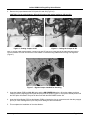
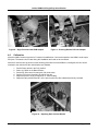
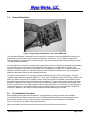
Collins KWM-2/2A Plug-N-Play Noise Blanker
1.0
General Description
Figure 1 Plug-N-Play Noise Blanker for the Collins KWM-2/2A
The Collins Noise Blanker is designed to be a “Plug-N-Play” accessory for the Collins KWM-2/2A transceivers. It
plugs directly into the NB power socket (J24) and connectors, J22 and J23. The only KWM-2 modification is
removing the factory jumper between J22 and J23 (this is the same modification that is required when the Collins
136 Noise Blanker is installed).
The noise blanker is connected to the transceiver’s signal path at all times. The Noise pulse amplifier and blanking
pulse forming network is not enabled until the KWM-2’s power switch is in the NB position. The gain of the
controlled IF amplifier is set with the IF gain adjust, which is adjusted for unity gain. The Threshold control can be
adjusted to activate the blanker at a level that causes no inter-modulation or distortion from any strong signals
adjacent to the primary frequency and activating the blanker.
The signal from the Variable IF is connected to the Noise Blanker through a J-FET source follower. This high
impedance input minimizes loading the KWM-2’s 1st mixer output. The signal from the JFET follower is split into two
paths. One path is coupled to the IF Amplifier, and the other to the Noise Pulse Amplifier. Both amplifiers have a
pass-band of approximately 300 KHz matching that of the KWM-2’s 1st mixer output. Noise pulses from the Noise
Amplifier are detected and converted to square positive pulses whose width is proportional to the detected noise
pulse at a repletion rate of 10 to 2000 pulses per second and a pulse width of 1 to 250 µSec. This ‘blanking pulse’
controls the output of the controlled IF amplifier. When a blanking pulse is present, the controlled IF amplifier is
turned off or ‘blanked’ for the duration of the pulse with an effective blanking of up to 50dB.
2.0
Pre-Installation Procedure
Before installing the Plug-N-Play Noise Blanker it is suggested that you become familiar with the KWM-2
documentation and the chassis component layout. It is assumed that the KWM-2 is functioning properly and in
good working condition. If not, a thorough checkout may be called for before installing the noise blanker.
Figure 2 is a picture of the KWM-2 front panel and controls.
Remove the KWM-2 from its enclosure and connect the power cable and turn the power on.
www.wynnwrks.com
Page 1 of 6
Collins KWM-2/2A Plug-N-Play Noise Blanker
Figure 2 The KWM-2/2A Front Panel and Controls.
Allow the KWM-2 a warm-up period of 15 minutes for stabilization. Connect the speaker to the KWM-2 audio output
RCA jack. The antenna is not used during this installation and need not be connected.
After the 5 minute warm-up period, use the following procedure to determine the KWM-2’s overall gain so that it can
be matched when the noise blanker is installed.
1.
2.
3.
4.
5.
Set the Power switch in the CAL position.
Select 14.2 MHz on the Band Selector.
Set the RF Gain control for max gain (fully clock-wise).
Set the VFO in the 0.0 position as read on the dial.
Adjust the Exciter Tuning for maximum ‘S’ meter reading and RECORD this value. It will used later to
adjust the noise blanker ‘gain’ to match this recorded value.
6. Un-plug the power cable from the KWM-2/2A before continuing with the noise blanker
installation.
3.0
Installing the Plug-N-Play Noise Blanker in the KWM-2/2A
1. Locate the RCA jacks J22 and J23 on the top of the chassis (Fig 3), and then locate them on the bottom of
the chassis. Note the shielded cable connecting the two jacks (Fig 4).
Figure 3 - Location of J22 & J23 (top)
www.wynnwrks.com
Figure 4 - Location of J22 & J23 (bottom)
Page 2 of 6
Collins KWM-2/2A Plug-N-Play Noise Blanker
2. Remove the jumper between the RCA jacks J22 and J23 (Fig 5 & 6).
CAUTION: Cut the cable between J22 and J23 and not the cables leading to J22 and J23.
Figure 5 – Cutting Jumper at J22
Figure 6 – Cutting the Jumper at J23
Note: A Jumper cable approximately 3 inches long with RCA jacks on each end can be fabricated and used to
connect between J22 and J23 when the noise blanker is removed during KWM-2/2A servicing and alignment
(Figure 7).
Figure 7 – Bypass Jumper Installed for Servicing
3. Insert the Adapter PCB into J22, J23 jacks, and the NB POWER J24 socket. Orient the adapter, and then
carefully insert by aligning the RCA jacks and plugs first as shown in figure 8. Then press vertically down until
the RCA jacks are seated. The pins will then mate with the NB POWER socket J24.
4. Insert the Noise Banker PCB into the Adapter PCB by orienting the pins on connectors such that they engage
pin for pin. Note: Misalignment of pins may cause damage to the noise blanker.
5. This completes the installation of the noise blanker.
www.wynnwrks.com
Page 3 of 6
Collins KWM-2/2A Plug-N-Play Noise Blanker
Figure 8 – Align Pins and Install PCB Adapter
4.0
Figure 9 – Pressing Blanker PCB into Adapter
Calibration
Allow the KWM-2 a warm-up period of 5 minutes for stabilization. Connect the speaker it the KWM-2 audio output
RCA jack. The antenna is not used during this installation and need not be connected.
After the 5 minute warm-up period, use the following procedure to set the KWM-2’s overall gain so that it can be
matched to the value before the noise blanker was installed.
1.
2.
3.
4.
5.
6.
Set the Power switch in the CAL position.
Select 14.2 MHz on the Band Selector.
Set the RF Gain control for max gain (fully clock-wise).
Set the VFO in the 0.0 position as read on the dial.
Adjust the Exciter Tuning for maximum ‘S’ meter reading.
Adjust the Gain potentiometer R7 on the pcb to match the value obtained previously recorded.
Figure 10 – Adjusting Gain of Noise Blanker
www.wynnwrks.com
Page 4 of 6
Collins KWM-2/2A Plug-N-Play Noise Blanker
Before re-mounting the KWM-2/2A chassis, check the KWM-2’s power output to insure that it is operating correctly,
and has the same power output before the noise blanker installation. The noise blanker has been designed for
minimum loading by using a high impedance input stage. However, if the KWM-2 has low output, an alignment of
T2 and L4 can correct this. Figure 11 shows the location of T2 and L4.
5.0
Bandpass IF Alignment
You may use the procedure outlined in the Collins Radio Instruction and Service Manual, or you may use the
following procedure for the Bandpass IF alignment.
The primary of T2 is best accessed from the bottom and the secondary from the top. L4 is adjusted from the top.
Use an alignment tool such as Walsco 2543 or equivalent (Figure 11).
1.
2.
3.
4.
5.
6.
Connect the KWM-2/2A RF output jack to a 50 ohm dummy load.
Set the OFF-ON-NB-CAL switch to ON and allow a 5 minute warm-up.
Set the meter switch in the GRID position.
Set the KWM-2/2A to the bottom of the 10 meter band (zero on the dial)
Set the Emission switch for USB.
Set the OFF-ON-NB-CAL switch to CAL, and adjust the EXCITER TUNING for a peak reading. Adjust the
primary of T2 (bottom slug) using the grid current peak indication. Caution not to adjust the slug to the full
extent of travel as damage may occur.
7. Set the KWM-2/2A to the top of the band (200 on the dial) and adjust the secondary of T2 (top slug) in the
same manner Caution not to adjust the slug to the full extent of travel as damage may occur.
8. Repeat until no additional improvement is seen.
9. Set the KWM-2/2A to mid-band (100 on the dial), and adjust L4 for peak grid current.
Figure 11 – Location of T2 and L4 (Top of Chassis)
Figure 12 – Location of T2 (Bottom of Chassis)
Recheck the system gain by replacing the blanker with a jumper wire for J22 and J23, and compare it to when the
blanker is in place (Figure 7).
www.wynnwrks.com
Page 5 of 6
Collins KWM-2/2A Plug-N-Play Noise Blanker
6.0
Operation
To enable the noise blanker, set the Power selector in the NB position. Fine tuning of the Threshold control can be
made by tuning to a station that has noise, and adjusting the potentiometer for the desired blanking effect. It’s that
simple. A solid state noise blanker has been installed to your Collins KWM-2/2A without circuit or mechanical
modifications.
Figure 13 – Adjusting Threshold Control
7.0
Terms and Conditions of Use
The materials contained in this document could contain technical inaccuracies or typographical errors. Changes are
periodically added to the information herein. Wynn Works, LLC may make improvements and/or changes in this
documents, and the product(s), and technical specifications described in this document at any time without notice.
Wynn Works, LLC also assumes no responsibility, and shall not be liable for, any damages to, or viruses that may
infect, your computer equipment or other property on account of your access to, use of, or browsing within this
document, or your downloading of any materials, data, text, images, video, or audio from this document. In no
event shall Wynn Works, LLC be liable for any incidental or consequential damages, lost profits, or lost data or any
indirect damages, even if Wynn Works, LLC has been informed of the possibility thereof.
© 2008 Wynn Works, LLC.
We at Wynn Works, LLC are interested in your experiences with our products, and welcome your comments. If you
have any questions, or require any assistance, we can be contacted during normal business hours:
Monday through Friday 9:00 AM to 5:00 PM Pacific Time.
Wynn Works, LLC.
299 Old County Road, Suite 2
San Carlos, CA 94070
Tel: (650) 591-3249
Fax:(650) 591-3232
Email: [email protected]
Doc #:Noise Blanker for Collins KWM-2_2A rev 2.doc
www.wynnwrks.com
Page 6 of 6