1
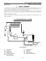
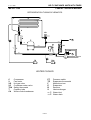
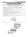
Ice Machines UK Ltd
Unit 10, LDL Business Centre, Station Road West, Ash Vale, Surrey, GU12 5RT
Tel: 01252 511611 Fax: 01252 511666
www.icemachines.co.uk e-mail: [email protected]
ICE CUBES MAKERS
SERVICE MANUAL
SELF CONTAINED UNITS WITH TIMER
CP 30SC E
CP 30 E
CP 45 E
CP 70 E
CP 120 E
LEV1FG-296
SELF CONTAINED UNITS WITH TIMER
COMPACT SERVICE MANUAL
F.A.G. SRL
ME-CPT1-199
INDEX
1.
2.
3.
4.
5.
HOW IT WORKS
1
1.A.
REFRIGERATION SYSTEM
1.A.a. Freezing cycle
1.A.b. Defrost cycle (harvest)
1.A.c. Air cooling
1.A.d. Water cooling
1
2
2
2
2
1.B.
WATER SYSTEM
1.B.a. Freezing cycle
1.B.b. Defrost cycle (harvest)
1.B.c. Ice storage bin
4
4
4
4
1.C.
ELECTRICAL SYSTEM
1.C.a. Water cooled models
5
8
INSTALLATION
9
2.A.
CONNECTIONS
9
2.B.
SET-UP
2.B.a. Air cooled condenser units
2.B.b. Water cooled condenser units
9
9
10
START-UP & TEST
10
3.A.
START-UP
10
3.B.
TEST
11
CLEANING
11
4.A.
CONDENSER CLEANING
11
4.B.
INTERNAL CLEANING & SANITIZING
4.B.a. Cleaning - To remove lime scale or other mineral deposits
4.B.b. Sanitizing - To remove algae or slime
12
12
13
GENERAL INFORMATION
14
5.A.
WEIGHTS & DIMENSIONS
14
5.B.
CUBE SIZE
15
5.C.
MODEL NUMBER BREAKDOWN
15
5.D.
GENERAL DATA
16
5.E.
PRODUCTION
5.E.a. Theoretical daily ice production - N. of cubes/24h
5.E.b. Theoretical daily ice production - kg/24h
17
17
18
5.F.
WATER VALVE & FLOW REGULATOR CHART
5.F.a. Air cooled
5.F.b. Water cooled
19
19
19
SELF CONTAINED UNITS WITH TIMER
COMPACT SERVICE MANUAL
F.A.G. SRL
ME-CPT1-199
1.
HOW IT WORKS
The system is very simple and efficient. The evaporator is built up connecting together a series of
reversed cups with a cooling coil. The refrigerant flows into the tubes while the pump sprays water
into the cups. Thus inside each cup, an ice cube grows layer by layer.
When the cubes are ready, harvest starts : hot gas flows through cooling coil of the evaporator and
fresh water enters on top of evaporator. This melts the outer surface of the cubes which fall into the
bin.
A new freezing cycle then begins.
When the bin is full of ice, the unit stops production. When a quantity of ice is taken away, the unit
restarts production.
1.A. REFRIGERATION SYSTEM
REFRIGERATION TUBING SCHEMATICS
↑ T
E
←
S
VG
↓
B
C
→
→
TE
CD
→
↑
F
V
←
←
230V
PT
mod. CP70 - CP120
AIR COOLED
C
V
VG
T
CD
PT
F
E
B
S
TE
Compressor
Fan motor
Hot gas valve
Capillary tube
Air cooled condenser
Pressure switch
CP70, CP120 only
PAG.1
Molecular sieve
Evaporator
Receiver
Heat exchanger
Evaporator thermostat
SELF CONTAINED UNITS WITH TIMER
COMPACT SERVICE MANUAL
F.A.G. SRL
ME-CPT1-199
1.A.a.Freezing cycle
1.
2.
3.
4.
5.
The compressor C pumps the refrigerant to the condenser CD or CA when the hot gas valve
VG is closed.
The liquid line reaches the evaporator E through the molecular sieve F and the capillary tube T.
In the evaporator the refrigerant expands, thus producing the freezing effect.
The refrigerant goes back to the compressor through the receiver/tank B and suction line/heat
exchanger S.
The freezing cycle ends when the evaporator thermostat TE reaches the set temperature thus
starting the TIMER; when the time is over, the refrigeration cycle ends and the VG hot gas
valve is opened.
1.A.b.Defrost cycle (harvest)
1.
2.
When the hot gas valve VG open, refrigerant flows directly from the compressor C to the
evaporator E and back to the compressor through S.
Duration of harvest is fixed by the timer. There is a delay in starting the TIMER in the defrost
period. The TIMER is energized when the evaporator thermostat TE reaches the preset high
'IN' temperature; for this reason the motor of the TIMER is connected directly with the
COMMON contact of the evaporator thermostat. When the harvest ends, the timer is deenergized, the hot gas valve VG is closed and a new freezing cycle begins.
1.A.c.Air cooling
1.
2.
Models with air cooled condenser, have a fan motor V which is always energized (mod. CP30,
CP45) or is switched on and off by the pressure switch PT, (mod.CP70, CP120) which senses
condensing pressure.
Pressure switch PT is factory set. After sale service is not allowed to make adjustments for any
reason.
1.A.d.Water cooling
1.
2.
3.
4.
Models with water cooled condenser, have a fan motor V which is always energized.
Water inlet to condenser is regulated by the pressure switch PT, which senses condensing
pressure and energizes or not the condenser water inlet solenoid valve VC.
The safety thermostat TSA feels condensing temperature, too. In case of excessive temperature,
due e.g. to water shortage, valve failure etc., it shuts down the unit. When temperatures
decreases, it starts again.
Condenser thermostats and pressure switch are factory set. After sale service is not allowed to
make adjustments for any reason.
PAG.2
SELF CONTAINED UNITS WITH TIMER
COMPACT SERVICE MANUAL
F.A.G. SRL
ME-CPT1-199
REFRIGERATION TUBING SCHEMATICS
↑ T
E
←
S
VG
↓
B
C
→
→
↑
⇒ 2
→
CA
F
V
VC
←
←
⇐1
230V
PT
TE
TSA
WATER COOLED
C
V
VG
VC
TSA
T
CA
PT
TE
F
E
B
S
Compressor
Fan motor
Hot gas valve
Condenser water valve
Safety thermostat
Capillary tube
Water cooled condenser
Pressure switch
Evaporator thermostat
Molecular sieve
Evaporator
Receiver
Heat exchanger
⇐c Water inlet
⇒d Water drain
PAG.3
SELF CONTAINED UNITS WITH TIMER
COMPACT SERVICE MANUAL
F.A.G. SRL
ME-CPT1-199
1.B. WATER SYSTEM
E
WT
SB
OF
mod. CP30 - CP45
CP70
⇐c
⇒d
⇒e
E
P
SB
WT
OF
mod. CP 120 only
P
⇒ 3
P
P
SB
WT
VA
E
OF
VA
⇒ 2
⇐1
Pump(s)
Spray bar(s)
Water tank
Inlet water valve
Evaporator
Overflow
⇐c Water inlet
⇒d Bin overflow drain
⇒e Tank overflow drain
1.B.a.Freezing cycle
1.
2.
3.
The pump P takes water from the water tank WT through a suction pipe and sends it to the
spray bar SB (two pumps and two spray bars for mod. CP120).
The water sprayed by the nozzles reaches the cooled cups on the evaporator E. A quantity of
water freezes and the excess falls again into the water tank.
The water inlet valve VA is closed.
1.B.b.Defrost cycle (harvest)
1.
2.
3.
4.
The water inlet valve VA is open. Fresh water goes up on top of evaporator, helping defrost.
From the top of the evaporator, water falls into the water tank and refills it.
Excess water is discharged by the overflow control OF.
Water pump(s) is not working.
1.B.c.Ice storage bin
1.
Water from melted ice is drained separately, and does not enter again into the water system.
PAG.4
SELF CONTAINED UNITS WITH TIMER
COMPACT SERVICE MANUAL
F.A.G. SRL
ME-CPT1-199
1.C. ELECTRICAL SYSTEM
• Compressor is always ON. Fan motor is regulated by the pressure switch PT only in models
CP70 & CP120. In models CP30sc, CP30 & CP45 fan motor is always ON.
• The bin thermostat TB opens, when the ice-feeler is in contact with ice. The unit then stops.
WIRING DIAGRAM
air cooled
A) Start of freeze cycle
B
M
TB
3
CP70 - CP120
B
B
PT
V
C
4
M
M
A
M
M
M
C
B
B
P
V
VG
R
B
C
a
b
NO
NC
V
P
TIMER
R
T
C
TE
2
B
C
compressor
ON
V
fan motor
ON (PT)
P
pump
ON
T
timer
OFF
a
micro a
C-NO
b
micro b
C-NO
VG
gas valve
OFF
VA
water valve
OFF
TE
evaporator
thermostat
WARM (C-4)
TB
bin thermostat
closed
4
R
V
VA
R
B
A) Start of freeze cycle. The pumps spray water to the cups on the evaporator which is freezing.
The evaporator thermostat TE has not reached set-point. It is in WARM position.
M
B
V
R
A
P
Brown
Blue
Green
Red Orange
Pink
PAG.5
SELF CONTAINED UNITS WITH TIMER
COMPACT SERVICE MANUAL
F.A.G. SRL
ME-CPT1-199
WIRING DIAGRAM
air cooled
B
M
3
B
PT
V
C
TB
4
M
CP70 - CP120
B
B) End of freeze cycle
M
A
M
M
M
C
C
P
NC
NO
V
V
R
TE
VG
B
T
b
a
B
P
TIMER
2
R
C
B
4
R
V
C
compressor
ON
V
fan motor
ON (PT)
P
pump
ON
T
timer
ON
a
micro a
C-NO
b
micro b
C-NO
VG
gas valve
OFF
VA
water valve
OFF
TE
evaporator
thermostat
COLD (C-2)
TB
bin thermostat
closed
VA
B
R
B
B) End of freeze cycle. The evaporator thermostat TE has reached the set-point. It is in COLD
position. The timer starts to complete freezing cycle.
WIRING DIAGRAM
air cooled
B
M
3
CP70 - CP120
B
B
PT
V
C
C) Start of defrost
TB
4
M
M
A
M
M
M
C
B
B
P
V
VG
R
B
C
a
b
NO
NC
V
P
TIMER
R
TE
2
T
C
B
4
R
V
VA
R
C
compressor
ON
V
fan motor
ON (PT)
P
pump
OFF
T
timer
OFF
a
micro a
C-NC
b
micro b
C-NC
VG
gas valve
ON
VA
water valve
ON
TE
evaporator
thermostat
COLD (C-2)
TB
bin thermostat
closed
B
C) Start of Defrost. Microswitches a and b are operated by the two levers and the rotating cam of
the timer. The pumps stop and the hot gas and water valves open. The evaporator thermostat is
still in COLD position. The motor of the timer stops.
PAG.6
SELF CONTAINED UNITS WITH TIMER
COMPACT SERVICE MANUAL
F.A.G. SRL
ME-CPT1-199
WIRING DIAGRAM
air cooled
B
M
3
CP70 - CP120
B
B
PT
V
C
D) Defrost
TB
4
M
M
A
M
C
NC
V
R
TE
VG
B
T
b
a
NO
V
P
TIMER
C
P
2
R
C
B
4
R
ON
V
fan motor
ON (PT)
P
pump
OFF
T
timer
ON
a
micro a
C-NC
b
micro b
C-NC
VG
gas valve
ON
VA
water valve
ON
TE
evaporator
thermostat
WARM (C-4)
TB
bin thermostat
closed
V
VA
B
compressor
M
M
B
C
R
B
D) Defrost. The evaporator thermostat switches to WARM position starting the motor of the Timer,
thus completing defrost.
WIRING DIAGRAM
air cooled
B
M
3
CP70 - CP120
B
B
PT
V
C
E) End of defrost
TB
4
M
M
A
M
C
B
R
B
NC
NO
V
VG
T
b
a
P
P
TIMER
C
V
compressor
ON
V
fan motor
ON (PT)
P
pump
ON
T
timer
ON
a
micro a
C-NO
b
micro b
C-NC
VG
gas valve
ON
VA
water valve
ON
TE
evaporator
thermostat
WARM (C-4)
TB
bin thermostat
closed
M
M
B
C
R
TE
2
C
B
4
R
V
VA
R
B
E) End of Defrost. Defrost ends when both levers reach top of the rotating cam of the timer. This is
not simultaneous but first the external micro a and then the internal micro b are activated.
PAG.7
SELF CONTAINED UNITS WITH TIMER
COMPACT SERVICE MANUAL
F.A.G. SRL
ME-CPT1-199
IT IS VERY IMPORTANT NOT TO CHANGE CONNECTIONS BETWEEN THE TWO
INTERNAL (a) AND EXTERNAL (b) MICROSWITCHES OF THE TIMER.
brown
external microswitch
internal microswitch
b
a
green
orange pin
red
TIMER
It is possible to manually put the unit in defrost cycle by turning the orange pin of the TIMER
clockwise.
1.C.a.Water cooled models
Water inlet to the condenser is regulated by the pressure switch PT, which energizes or not the
condenser water inlet solenoid valve VC, sensing condensing pressure.
The safety thermostat TSA feels condensing temperature, too. In case of excessive temperature, due
e.g. to water shortage, valve failure etc., it shuts down the unit. When temperatures decreases, it
starts again.
A) Start of freeze cycle
WIRING DIAGRAM
water cooled
B
M
3
VC
B
PT
4
M
C
M
A
B
C
TB
2
M
TSA
4
M
M
B
B
B
M
V
P
V
VG
R
B
C
a
b
NO
NC
V
P
TIMER
C
R
T
C
TE
2
B
4
R
V
VA
C
compressor
ON
V
fan motor
ON (PT)
P
pump
ON
T
timer
OFF
a
micro a
C-NO
b
micro b
C-NO
VG
gas valve
OFF
VA
water valve
OFF
TE
evaporator
thermostat
WARM (C-4)
TB
bin thermostat
closed
safety
thermostat
closed
TSA
R
B
All the other diagram are similar to the air cooled ones, provided you change the V fan motor with
the condenser water inlet valve VC , and you add the safety thermostat TSA and the fan motor V.
PAG.8
SELF CONTAINED UNITS WITH TIMER
COMPACT SERVICE MANUAL
F.A.G. SRL
ME-CPT1-199
2.
INSTALLATION
2.A. CONNECTIONS
1. Choose a location far from heating sources and in a well ventilated dry place, not dusty, near
water inlet & drain connections.
2. Provide enough clearance at both sides and at rear of the unit (20 cm at least).
DO NOT USE UNIT OUTSIDE AND DO NOT EXPOSE IT TO RAIN.
3. Set upstream of the units an electrical multi-pole disconnect switch having a contact separation
of at least 3 mm in all poles. Switch rating shall comply with power specifications of each icemaker, as per specifications given in the plate on rear of each unit.
ALL CONNECTIONS SHOULD BE MADE IN ACCORDANCE WITH EXISTING
LOCAL ELECTRICAL REQUIREMENTS.
4. Power supply must match voltage specifications on registration plate on rear of unit. +/- 6%
deviation permitted. On higher rushes no assurance of correct operation is given.
5. Water inlet should be regulated by a 3/4" threaded tap, for an easy installation of the supply hose.
ATTENTION! CONNECT UNIT TO DRINKING (POTABLE) WATER ONLY.
6. Check if water inlet pressure is between 1 to 3 bar. If it is higher, install a pressure reducer set at
2,5 bar.
7. Water outlet must be at ground level connected to an open vented siphon.
2.B. SET-UP
2.B.a.AIR COOLED CONDENSER UNITS
1. Unpack the ice maker without turning the unit upside down, check for damage, remove all
cartons and the wooden pallet.
2. Remove the bag with the accessories from inside the unit. Take care of the Final User Manual
and give it to your customer. Remove the water blinds assembly. Check that the water spray-bar
and the internal ice chute are in the correct position, then re-install water blinds assembly.
3. Connect the unit to the external multi-pole switch for electric supply.
4. Check that the unit is perfectly level. If required, adjust leveling feet.
5. Connect the water inlet solenoid valve to the water mains tap with the rubber water supply tube.
6. Connect a drain hose to the water outlet of the unit and the open vented siphon at floor level.
7. Clean walls and bottom of storage bin with a wet cloth.
8. Open tap on water mains and check for leakage.
9. Switch on main external disconnect switch.
10.The unit starts in defrost at first installation. Water is charged and fills water tank. When the
timer ends the defrost cycle, the freezing cycle begins.
11.After a shut-off period, it is possible that the unit will not re-start in defrost. In this case or in
case more water is needed, turn clockwise the orange pin of the timer with a screwdriver, until
the unit goes in defrost.
12.Always charge fresh water before starting ice production, at first installation and after a long
shut-off period.
To start and stop unit, only use the external disconnect multi-pole switch.
PAG.9
SELF CONTAINED UNITS WITH TIMER
COMPACT SERVICE MANUAL
F.A.G. SRL
ME-CPT1-199
2.B.b.WATER COOLED CONDENSER UNITS
1. Follow steps 1 to 12 as described before (2.B.a).
2. Water inlet to the condenser is through the same water inlet solenoid valve, except for the fact
that the valve has one way-in and two solenoid operated way-out.
3. Drain out of the condenser is collected in the same drain-out connector.
1
air & water cooled installation
2
1. multi-pole disconnect switch
2. water mains tap
3. open vented siphon at floor level
3
fig. 2.B.1
3.
START-UP & TEST
When all the installation procedures have been completed, and all panels that should have been
removed, have been replaced in position, you can start-up the unit.
3.A. START-UP
1. Clean walls and bottom of storage bin with a wet cloth.
If needed, follow instructions for sanitizing the storage bin and/or the ice-maker.
2. Open tap on water mains and check for leakage.
Always charge water before starting ice production at first installation, or after a shut-off period.
3. Ambient temperature must range 10°C to 43°C .
Water temperature must be between 10°C and 25°C.
4. Switch main external disconnect switch on.
To switch unit ON and OFF operate on the external disconnect switch only.
5. Unit starts production.
Within half an hour the first ice cubes will fall into the storage bin.
6. For best performance, we suggest that ambient temperature should be between 12°C and 38°C.
PAG.10
SELF CONTAINED UNITS WITH TIMER
COMPACT SERVICE MANUAL
F.A.G. SRL
ME-CPT1-199
3.B. TEST
1. Wait three producing cycles before making any adjustment, then check the ice cubes. They must
have a small dimple. If they are too empty, turn the adjusting screw of the ice-control thermostat
clockwise to '+'. If they are too full, turn the screw counter clockwise to '-'.
2. Always make slight adjustments and wait for results. Do not insist on obtaining a full cube
without any dimple by adjusting the evaporator thermostat (ice-control) to full '+'.
Especially with hot external temperatures, adjusting the evaporator thermostat (ice-control) to
full '+' will cause the unit to have very long producing cycles, with a great decrease in production.
It is also possible that too full cubes won't fall into the bin during the defrost cycle and so they
will be cut and melted by water spray, obtaining the opposite of what thought.
3. If cubes are white or not complete, clean spray bar and nozzles.
4. With ice in contact with the ice bin level feeler inside the bin, the unit should stop within 1 min.
If not, slightly turn the adjusting screw of the bin thermostat counter clockwise towards
'SUMMER' until the unit stops. With the feeler cleared from ice, the unit should restart within 5
min. If not, screw slightly clockwise towards 'WINTER'.
5. To reach thermostats or Timer remove front panel.
6. Final User is not allowed to change adjustments of the thermostats or to service unit.
With water and/or ambient temperature below 10°C, to help ice cubes fall into the bin, it is possible
to increase duration of harvesting operating on the adjustable cam of the TIMER.
Timer
lock screw
1
3
To change duration of harvest cycle, loosen the lock
screw releasing the moving cam.
Change position of the cam referring to the numbers
printed on the orange part.
Lock the cam with the screw.
5
7
fig. 3.B.1
orange pin
4.
CLEANING
CAUTION ! : HAZARDOUS MOVING PARTS INSIDE MOTOR COMPARTMENT !
Do not operate with panels removed !
DANGER ! : ELECTRIC SHOCK HAZARD !
Disconnect power before servicing unit !
4.A. CONDENSER CLEANING
Clean condenser every month.
Disconnect power, remove front panel and brush away dust and dirt from the condenser with a hard
brush and a vacuum cleaner.
CAUTION: the fins of the condenser have sharp edges which might hurt your fingers.
A dirty condenser causes loss of production and may jeopardize correct operation of the unit.
PAG.11
SELF CONTAINED UNITS WITH TIMER
COMPACT SERVICE MANUAL
F.A.G. SRL
ME-CPT1-199
4.B. INTERNAL CLEANING & SANITIZING
CAUTION ! : DO NOT MIX CLEANER AND SANITIZING SOLUTION TOGETHER
WARNING ! WEAR RUBBER GLOVES AND SAFETY GOGGLES WHEN HANDLING
ICE MACHINE CLEANER OR SANITIZER
4.B.a.Cleaning - To remove lime scale or other mineral deposits
1. Disconnect power and remove front panel and, for easier operation, top panel and door.
2. Discard all the ice present in the ice bin.
3. To drain water tank, remove water blinds and ice chute and gently remove the moving part of the
overflow regulator (fig. 4.B.1).
4. To clean tank and water system, add an approved liquid ice machine cleaner to water tank
following the directions of the manufacturer of the product.
Otherwise you can pour two spoons of vinegar or citric acid in the water tank.
5. Re-place all items removed (overflow regulator, spray bar, ice chute and water blinds) and start
the unit with the Timer in defrost position. Fresh water will be charged.
6. Leave the unit work for some producing cycles.
7. To rinse, place the Timer in defrost position allowing fresh water in. To drain water follow
instructions as per #3.
8. To clean ice bin discard the ice produced and gently rub sides and bottom of the bin with a cloth
using the same cleaning solution.
fig. 4.B.1
For a more thorough cleaning you can remove spray bars, ice chute and water blinds and clean them
separately.
fig. 4.B.2
water tank
rubber hose
spray bar
ice chute
water blinds
PAG.12
SELF CONTAINED UNITS WITH TIMER
COMPACT SERVICE MANUAL
F.A.G. SRL
ME-CPT1-199
When you re-assemble all the parts removed for cleaning, it is very important to verify that the
nozzles are free to spray water and that the ice chute does not interfere with the spray bar. (nozzle
must be in the middle of the rows of the ice chute fig 4.B.3).
fig 4.B.3
4.B.b.Sanitizing - To remove algae or slime
1. To sanitize ice storage bin, take away all the ice and gently wipe walls and bottom of the bin with
a cloth and a sanitizing cleaner following the directions of the manufacturer of the product.
You can use household products or a diluted solution of sodium hypoclorite (bleach).
2. To sanitize water tank and all the water system, follow instructions for cleaning using a sanitizing
product instead of a cleaner.
If your water is rich in chlorine, you will not obtain a full clear and crystal ice-cube, and the ice will
melt sooner.
It may be necessary to connect water supply to a water treatment system to inhibit scale formation,
filter sediment or remove chlorine taste.
Water treatment will pay for itself through decreased maintenance, higher efficiency and quality of
product.
PAG.13
SELF CONTAINED UNITS WITH TIMER
COMPACT SERVICE MANUAL
F.A.G. SRL
ME-CPT1-199
5.
GENERAL INFORMATION
5.A. WEIGHTS & DIMENSIONS
L
H
1
2
3
B
D
P
C
A
1)
2)
3)
L
MODEL
CP 30SC E
CP 30SC E W
CP 30 E
CP 30 E W
CP 45 E
CP 45 E W
CP 70 E
CP 70 E W
CP 120 E
CP 120 E W
dimensions
Electrical cord
Water inlet 3/4”
Water drain ø 20 mm
P
mm
H
A
B
C
405
430
650
55
90
100
70
495
560
745
220
145
275
65
495
560
815
220
145
275
65
710
560
900
425
195
485
120
710
560
1270
425
195
485
120
mm
PAG.14
D
mm
SELF CONTAINED UNITS WITH TIMER
COMPACT SERVICE MANUAL
F.A.G. SRL
ME-CPT1-199
5.B. CUBE SIZE
Two types of ice cubes are available, the standard cube and the big cube, except the model CP30SC
which is available only with the standard cube.
The standard cube has an average weight of 19 grams, while the big one has an average weight of
32 grams.
Shapes and dimensions are explained in fig. 5.B.1
38
33
34
40
fig. 5.B.1
standard cube 19g
big cube 32g
The two versions can be easily detected because the models producing the big cube 32g show the
letter G after the model number.
5.C. MODEL NUMBER BREAKDOWN
Let’s take for example model CP 70E W G X (-- means no letter)
CP 70 E
W G
X
voltage
X = 220V 60Hz
Y = 115V 60Hz
-- = 220-240V 50Hz
cube size
G = big cube 32g
-- = standard cube 19g
condensation
W = water cooled
-- = air cooled
refrigerant
E = R134a
Z = R404a
-- = R12 (obsolete)
model
brand
CP = compact
( e.g. CP70EWGX = compact 70, R134a, water cooled, big cube, 220/1/60).
PAG.15
SELF CONTAINED UNITS WITH TIMER
COMPACT SERVICE MANUAL
F.A.G. SRL
ME-CPT1-199
5.D. GENERAL DATA
MODEL
CP 30SC E
CP 30 E
CP 30 E G
CP 45 E
CP 45 E G
CP 70 E
CP 70 E G
CP 120 E
CP 120 E G
TIMER
N. OF CUBES Q.TY OF ICE
THEORETICAL
ADJUSTMENT PER CYCLE PER CYCLE WATER USAGE l/h
water cooled
DEFROST
IN GRAMS air cooled
2,5
24
456
9
32
2,5
24
456
9
32
3,5
20
640
13
54
3,5
32
608
13
55
4,5
28
896
13
55
3,5
52
988
13
60
4,5
44
1536
13
60
3,5
104
1976
22
62
4,5
96
3072
22
62
REFRIGERANT
CHARGE g
MODEL
air cooled water cooled
CP 30SC E
CP 30 E
CP 30 E G
CP 45 E
CP 45 E G
CP 70 E
CP 70 E G
CP 120 E
CP 120 E G
32
41
41
44
44
66
66
86
86
35
46
46
50
50
71
71
93
93
0,16
0,31
0,31
0,33
0,33
0,45
0,45
0,63
0,63
2,5
2,5
2,5
3,2
3,2
5,0
5,0
6,2
6,2
400
400
400
510
510
800
800
1150
1150
PAG.16
10A
10A
10A
10A
10A
10A
10A
16A
16A
¼ Hp
¼ Hp
¼ Hp
³⁄⁄8 Hp
³⁄⁄8 Hp
½ Hp
½ Hp
1 Hp
1 Hp
210
210
210
220
220
370
350
350
330
180
180
170
195
195
300
285
285
270
SELF CONTAINED UNITS WITH TIMER
COMPACT SERVICE MANUAL
F.A.G. SRL
ME-CPT1-199
5.E. PRODUCTION
5.E.a.THEORETICAL DAILY ICE PRODUCTION - N. of cubes/24h
Average production at different ambient temperatures with water temperature of 10°C
MODEL
CP 30SC E
CP 30 E
CP 30 E G
CP 45 E
CP 45 E G
CP 70 E
CP 70 E G
CP 120 E
CP 120 E G
15°C
1600
1600
1020
2050
1340
3500
2270
6100
4325
21°C
1460
1460
920
1800
1160
3300
2110
5700
3995
25°C
1350
1350
840
1600
1015
3040
1920
5300
3670
30°C
1190
1190
730
1500
935
2830
1760
4950
3375
38°C
1040
1040
630
1400
835
2600
1620
4600
3130
Average production at different ambient temperatures with water temperature of 15°C
MODEL
CP 30SC E
CP 30 E
CP 30 E G
CP 45 E
CP 45 E G
CP 70 E
CP 70 E G
CP 120 E
CP 120 E G
15°C
1420
1420
910
1900
1245
3300
2140
5600
3985
21°C
1310
1310
820
1700
1060
3200
2040
5350
3740
25°C
1200
1200
740
1500
945
3000
1880
5100
3505
30°C
1090
1090
665
1400
870
2790
1740
4800
3265
38°C
970
970
580
1300
765
2500
1540
4500
3030
Average production at different ambient temperatures with water temperature of 21°C
MODEL
CP 30SC E
CP 30 E
CP 30 E G
CP 45 E
CP 45 E G
CP 70 E
CP 70 E G
CP 120 E
CP 120 E G
15°C
1250
1250
790
1700
1080
3250
2090
5200
3655
21°C
1150
1150
720
1500
945
3140
2010
5000
3495
25°C
1080
1080
670
1400
860
2940
1870
4800
3330
30°C
1000
1000
600
1200
735
2710
1650
4600
3075
38°C
900
900
530
1100
620
2400
1430
4400
2875
Production could change of ± 5/10% depending on cube size and cube concavity adjustment.
PAG.17
SELF CONTAINED UNITS WITH TIMER
COMPACT SERVICE MANUAL
F.A.G. SRL
ME-CPT1-199
5.E.b.THEORETICAL DAILY ICE PRODUCTION - kg/24h
Average production at different ambient temperatures with water temperature of 10°C
MODEL
CP 30SC E
CP 30 E
CP 30 E G
CP 45 E
CP 45 E G
CP 70 E
CP 70 E G
CP 120 E
CP 120 E G
15°C
30,4
30,4
32,64
38,95
42,88
66,5
72,64
115,9
138,4
21°C
27,74
27,74
29,44
34,2
37,12
62,7
67,52
108,3
127,84
25°C
25,65
25,65
26,88
30,4
32,48
57,76
61,44
100,7
117,44
30°C
22,61
22,61
23,36
28,5
29,92
53,77
56,32
94,05
108
38°C
19,76
19,76
20,16
26,6
26,72
49,4
51,84
87,4
100,16
Average production at different ambient temperatures with water temperature of 15°C
MODEL
CP 30SC E
CP 30 E
CP 30 E G
CP 45 E
CP 45 E G
CP 70 E
CP 70 E G
CP 120 E
CP 120 E G
15°C
26,98
26,98
29,12
36,1
39,84
62,7
68,48
106,4
127,52
21°C
24,89
24,89
26,24
32,3
33,92
60,8
65,28
101,65
119,68
25°C
22,8
22,8
23,68
28,5
30,24
57
60,16
96,9
112,16
30°C
20,71
20,71
21,28
26,6
27,84
53,01
55,68
91,2
104,48
38°C
18,43
18,43
18,56
24,7
24,48
47,5
49,28
85,5
96,96
Average production at different ambient temperatures with water temperature of 21°C
MODEL
CP 30SC E
CP 30 E
CP 30 E G
CP 45 E
CP 45 E G
CP 70 E
CP 70 E G
CP 120 E
CP 120 E G
15°C
23,75
23,75
25,28
32,3
34,56
61,75
66,88
98,8
116,96
21°C
21,85
21,85
23,04
28,5
30,24
59,66
64,32
95
111,84
25°C
20,52
20,52
21,44
26,6
27,52
55,86
59,84
91,2
106,56
30°C
19
19
19,2
22,8
23,52
51,49
52,8
87,4
98,4
38°C
17,1
17,1
16,96
20,9
19,84
45,6
45,76
83,6
92
Production could change of ± 5/10% depending on cube size and cube concavity adjustment.
PAG.18
SELF CONTAINED UNITS WITH TIMER
COMPACT SERVICE MANUAL
F.A.G. SRL
ME-CPT1-199
5.F. WATER VALVE & FLOW REGULATOR CHART
5.F.a.AIR COOLED
ELBI single water solenoid valve
A
TYPE
1,2 l/m
2,5 l/m
2,5 l/m
COLOR
WHITE
ORANGE
ORANGE
FLOW REGULATOR - A MODELS
CP 30SC E - CP 30 E - CP 45 E
CP 45 EG **
CP 70 E - CP 120 E
** big cube versions only
5.F.b.WATER COOLED
ELBI double water solenoid valve
A
B
TYPE
1,2 l/m
2,5 l/m
2,5 l/m
FLOW REGULATOR - A - ice making water inlet
COLOR
MODELS
CP 30SC EW - CP 30 EW CP 45 EW
WHITE
ORANGE
CP 45 EWG **
CP 70 EW - CP 120 EW
ORANGE
TYPE
0,5 l/m
1,2 l/m
2,5 l/m
FLOW REGULATOR - B - condenser water inlet
COLOR
MODELS
CP 30SC EW - CP 30 EW
RED
CP 45 EW
WHITE
CP 70 EW - CP 120 EW
ORANGE
PAG.19