1
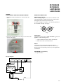
Stand and Bowl Mixer
RI7200/00
RI7200/01
HR7200/00
HR1576/00
Philips Consumer Lifestyle
Version A
Service Manual
PRODUCT INFORMATION
Safety
• This product meets the requirements regarding
interference suppression on radio and TV.
• After the product has been repaired, it should function
properly and has to meet the safety requirements as
officially laid down at this moment.
TECHNICAL INFORMATION
• Voltage
: 220 V
• Frequency
: 50 Hz - 60 Hz
• Power
: 400 W
• Cord length
: 1,25 m
• Colour appliance
: White
• Motor
: Serles wound
Statically and dynamically
balanced
Self lubricated
• Transmission ratio
between rotor spindle
and gearwheel
: 21½ : 1
• Speeds beaters
: Switch position 1 - 545 rpm
Switch position 2 - 600 rpm
Switch position 3 - 710 rpm
Switch position 4 - 810 rpm
Switch position 5 - 900 rpm
Turbo position
- 1010 rpm
Dimensions
• Length
:
• Width
:
• Height
:
• Weight
:
Published by Philips Consumer Lifestyle
12/11
Printed in the Netherlands
350 mm
370 mm
165 mm, 370 mm (incl. Mixer)
1660 g (without Beaters)
© Copyright reserved
Subject to modification
RI7200/00
RI7200/01
HR7200/00
HR1576/00
STAND:
DISASSEMBLY- AND RE-ASSEMBLY ADVISE
• Push with a small screwdriver the 2 hooks inside the
stand.
REPAIR INSTRUCTION
Mounting gearwheels
When mounting the gearwheels make sure that the cams
of the gearwheels are situated at the front of the beaters.
The angle between the beaters must be 45°.
So when carrying out a repair be sure that the gearwheels
are mounted correctly (see Fig. 1).
90°
45°
Fig. 1
• Press both arm-flaps like shown, that you can remove the
arm from the stand.
Lubrication
Use graphite grease code no. 4822 390 20004 to grease the
appliance on the following points:
1. Spaces between the teeth of the wormwheels.
2. Both sides of the wormwheel shaft.
Motor
The motor cannot operate properly, when, due to
contamination, carbon brush is unable to move freely in
guide bush and consequently cannot be pressed against the
commutator.
OPTIONAL (accessories)
• No specific issues.
Circuit diagram
Motor assy
Black
1
2
Green Red
Orange
Max speed
3
4
5
Brown
Blue
MAINS
2-5
RI7200/00
RI7200/01
HR7200/00
HR1576/00
3D view (Mixer)
5
8
6
14
2
13
9
1
7
3
10,11
12
2
3-5
RI7200/00
RI7200/01
HR7200/00
HR1576/00
Partslist (Mixer)
Pos
Service code
1
3
4206 136 66211
4206 136 66201
4206 136 65541
4206 136 65881
4206 133 01931
4
5
6
7
8
4206 133 53121
4206 133 01891
4206 132 86951
4206 136 64531
4206 136 66161
Motor cushion
Ejector knob
Ejector spring
Switch assy 5 speed + Cables
Fleximix lock button + Brackets
9
10
11
4206 133 02571
4206 136 65361
4206 136 65371
4206 136 65901
4206 133 02791
Turbo knob
Cordset assy 6 A
Cordset assy 3 A
Cordset assy 10 A / 250 V
Cord grommet
12
13
14
4206 133 09971
4206 133 01861
4206 132 86981
Insulator tab for terminal
FlexiMix lock button
Turbo knob spring
2
Description
Motor assy 220 V
Motor assy 127 V
Housing Walita
Housing Philips
Bottom housing (non driven)
Remark
RI
7200/00
RI
7200/01
X
White
White
Oyster
White
White
White
White
X
HR
7200
HR
1576
X
X
X
X
X
X
X
X
X
X
X
X
X
X
X
X
X
X
X
X
X
X
X
X
X
X
X
X
X
X
X
X
X
X
X
X
X
X
X
X
X
X
X
X
X
X
X
X
X
X
X
X
= changed
4-5
RI7200/00
RI7200/01
HR7200/00
HR1576/00
3D view & partslist (Stand)
15
16,17
24
25
26
27
18
21
19
22
20
23
Pos
Service code
Description
15
16
17
18
19
4203 133 02071
4203 133 02081
4206 132 86921
4206 133 02061
4206 136 65581
Inlay (non driven)
Lock
Spring (lock)
Arm (non driven)
Stand assy
20
21
22
23
24
4203 133 53300
4206 132 86911
4206 133 02101
4206 133 02091
4206 136 64681
Rubber feet
Spring (release knob)
Release knob
Bowl
Strip beater bearing left assy
4206 136 62121
4206 136 64701
4206 136 62021
4206 136 64711
4206 136 64721
Strip beater bearing left assy (local)
Strip beater bearing right assy
Strip beater bearing right assy (local
Dough hook left assy
Dough hook right assy
25
26
27
= changed
White
1 pcs
3,5 L
RI7200
HR7200
X
X
X
X
X
X
X
X
X
X
X
X
X
X
X
X
X
X
X
X
HR1576
X
X
X
X
X
X
X
X
X
X
5-5


![Lifts Part 4: Operational Management [PDF 707Kb]](http://vs1.manualzilla.com/store/data/006003154_1-8f988a4c31a2e96372488ae8439271db-150x150.png)