1
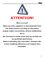
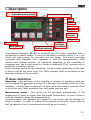
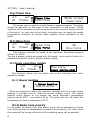
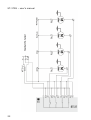
ST-37 – user's manual
TECH
Declaration of Conformity No. 4/2004
Hereby, we declare under sole responsibility that the ST37
230V
50Hz
thermoregulator
manufactured
by
TECH,
headquartered in Wieprz 1047A, 34-122 Wieprz, is compliant
with the Regulation by the Ministry of Economy. (Journal of
Laws Dz.U. 155 Item 1089) of July 21, 2007 implementing
provisions of the Low Voltage Directive (LVD) 2006/95/EC of
January 16, 2007.
The ST-37 controller has been tested for electromagnetic
compatibility (EMC) with optimal loads applied.
For compliance assessment, harmonized standards were
used:
PN-EN 60730-2-9:2006.
-2-
TECH
ATTENTION!
HIGH
VOLTAGE!
Make sure the regulator is disconnected from
the mains before working on the power
supply (cable connections, device installation,
etc.)!
All connection works must only be carried out
by qualified electricians.
Before activating the controller, measure the
motor resetting efficiency and inspect wire
insulation.
-3-
TECH
I. Description
Controller condition
(operation/maintenance))
Pomps operation mode
Alarm
Feeder
Fan
CH pump
Network
switch
CHW pump
Plus (up)
Minus (down)
Entrance to menu,
settings approval
Exit,
settings
cancellation
Temperature regulator ST–37 is designed for CH boilers equipped with a
wormwheel or piston feeder. It controls the water circulation pump (C.H.), the
usable hot water pump, fan operation and fuel feeder. This device may also
cooperate with standard room regulator or with RS communication, GSM
module and Internet module. An additional advantage is the possibility to
cooperate with two mixing valves by means of additional ST-61 modules with a
possibility of weather control.
Each controller should be set individually, for own needs, depending on the type
of fuel as well as the boiler type. The TECH company shall not be liable for any
incorrect settings of the controller.
II. Basic definitions
Operation - after activation of the controller it switches to operation mode and
on the display the symbol is shown. It is the basic functioning condition of the
regulator, in which blow-in works all the time, while fuel feeder's operation time
is set by the user (both operation time and pause time are set).
Maintenance mode - this mode will be activated automatically, if the
temperature is equal or higher than the preset Temperature. In such a case in
order to smoothly reduce the temperature of
circulating water the regulator will supply the fuel slower and the display will
show a symbol: In order to reduce the temperature correctly, pause time as
well as operation time in maintenance should be set correctly.
-5-
ST-37 – user's manual
III. Functions of the regulator
This section describes functions of the regulator, method of changing the
settings and menu navigation.
III.a) Main page
42oc
CO
56oc
Set
During normal operation of the regulator on LCD display, the homepage is
visible, on which the following information is displayed:
● Boiler temperature
● Preset temperature
● Pumps operation mode (see chapter 2.i)
● Boiler operation condition (-operation |- maintenance)
This screen enables fast change of the preset Temperature using PLUS
and MINUS buttons. Pressing the OPTIONS button moves the user to menu
where the first two functions are displayed. You can navigate the menu, using
PLUS and MINUS buttons. Pressing the OPTIONS button transfers to submenu
or activates the selected option. To exit the menu or cancel setting 1 button
should be used.
Pressing the EXIT button during the main screen view will result in display
of screen view change menu, (see chapter 2.b). In the case of lack or damage
of usable hot water sensor or selection of house heating operation mode,
instead of the current temperature, XX.X will be displayed.
III.b) Screen view
In this function, the user may choose one of the three main
thermoregulator operation screens. They are:
➔ CH Screen (displayed: temperature of the boiler - current and preset), using
PLUS/MINUS buttons the set CH may be changed directly from the main screen.
➔ Usable Hot Water Screen (the boiler temperature is displayed – current and
preset), using
PLUS/MINUS buttons the set boiler temperature may be changed directly from
the main screen.
➔ Parameters (feeder's temperature [P] and mosfet transistor [M]
and current hour are displayed).
➔ Valve 1 (displays operation parameters of the first valve – current and preset
temperature behind the valve and the percentage of its opening), using
PLUS/MINUS buttons, you can change the valve preset directly from the main
screen.
➔ Valve 2 (displays operation parameters of the second valve – same as for the
first valve)
-6-
ST-37RS – user's manual
III.c) Preset CH temperature
This option is used to adjust the set boiler temperature. The user may
change the temperature range of the boiler from 45°C to 80°C. The set CH
can also be changed directly from the main controller screen with PLUS and
MINUS buttons.
III.d) Usable Hot Water preset temperature
This option is used to adjust the set value of the hot utility water
temperature. The user may change this temperature within the range of
40°C to 75°C.
III.e) Manual operation
42oc
CH
56oc
Set
Manual operation
Operation time
For the user's convenience, the regulator is equipped with a Manual
operation mode. In this function, each executive element is switched on and
off independently from others.
□ Feeder
Blow in-force
□ Fan
□ CH pump
□ HUW pump
□ Alarm
Pressing the OPTIONS button activates the engine of the chosen
device (or alarm) which remains activated until OPTIONS button is pressed
again.
The blow-in power, where the user has the possibility to set any rotational
speed of the fan in manual operation, is additionally available.
III.f) Operation time*
42oc
CH
56oc
Preset
Manual operation
Operation time
7 seconds
Pause time
*This function is active only for the boiler with a wormwhel feeder. This
option is used to set the operation time of the fuel feeder. The operation
time should be set depending on the used fuel and the type of the boiler.
7
ST-37RS – user's manual
III.g) Pause time
42oc
56oc
CH
Preset
Pause time
Blow force
00:30 min:sek
Pause time
The pause time is used to set the feeder's operation pause. The pause
should be adjusted to the type of fuel combusted in the boiler. Wrong
selection of the operation as well as pause time may result in faulty function
of the boiler, i.e. coal may not be burnt, the boiler may not reach the preset
temperature. Selection of proper times enables correct operation of the
boiler.
III.h) Blow force
42oc
56oc
CH
Preset
Pause time
Blow force
80
Blow force
This function controls the speed of fan operation. Regulation range is
within 1 to 100%.
The fan is always initially activated with full speed – as a result of which it is
possible to activate it with a slightly dusted engine.
III.i) Pump operation modes
42oc
CH
56oc
Preset
Blow force
pumps operat.mode
This function allows you to select one of the following four boiler
operation modes:
III.i.1) House heating
■ House heating
□ HUW priority
When you select this option the controller switches over to a mode where
heating is provided only to heat the central heating circuit. The central
heating pump begins to run above the pump activation temperature
(factory set at 38OC - see Section III.g). The pump will turn off below this
temperature (minus a hysteresis of 2°C).
III.i.2) Boiler tank priority
In this mode, the boiler tank (hot water) pump will be switched on first to
run until the set-point temperature is reached (see Section II.e), after which
the pump will be turned off and the CH circulating pump will be enabled.
8
ST-37RS – user's manual
The central heating pump will run all the time until the boiler tank
temperature drops below its set-point by the hot water hysteresis value. At
that moment the CH pump will turn off and the HW pump will turn on (both
pumps operating alternately).
□ House heating
■ HUW priority
In this mode the fan and the feeder are run only up to 62 OC as measured
at the boiler (instantaneous set-point) so as to prevent overheating of the
boiler.
NOTE: The boiler must be fitted with check valves on the central heating
and hot water pump circuits. The valve mounted on the hot water pump is
to prevent drawing hot water from the boiler tank.
III.i.3) Pumps in parallel
■ Pomps paralle
□ Summer mode
In this mode both pumps begin to run together (in parallel) above the
pump activation temperature. However, these temperatures may vary for
each pump, depending on your settings (see Sections III.g-h). When this is
so one of the pumps will switch on earlier than the other one, but after both
thresholds are crossed both pumps will run together. The central heating
pump will run all the time while the hot water pump will turn off when the
boiler tank set-point temperature is reached. It will turn on again when the
temperature drops by the preset HW hysteresis value below its set-point.
III.i.4) Summer mode
□ Pomps parallel
■ summer mode
Once this function is activated the central heating pump will be off and the
DHW pump will turn on above the preset activation temperature (see
Section III.h) and will work continuously until the temperature drops below
the activation temperature by the hot water hysteresis value or until the
following conditions are met:
(boiler temperature) + 2°C ≤ (boiler tank temperature)
In summer mode you only enter the set-point temperature of the boiler,
which is also understood to mean the set-point temperature of the boiler
tank.
9
ST-37RS – user's manual
III.j) Operation in maintenance*
62oc
56oc
Operat in maint.
20 sekund
CH
Preset | Pause in maintn
Operat. In maint
* This function is active only for the boiler with a wormwhel feeder. This
option is used to set the time of feeder's operation when the boiler is in the
maintenance mode.
III.k) Pause in maintenance
62oc
56oc
Operat.In maint.
CH
Preset | Pause in maint.
30:00 min:sek
Pause i maint
The function of pause in maintenance is used for setting fuel feeding
pause time of maintenance mode. Wrong selection of the operation time as
well as the pause may result in further increase in temperature or
unintentional extinguishing of the boiler, or conditions in which it may result
in burning of the fuel in the fuel container.
III.l) Fan in maintenance
62oc
56oc
Fan in maintn
CH
Preset | Weekly control
Working time
Pause time
This option makes it possible to select appropriate operation and standstill
time (pause time) of the fan in maintenance (the so-called blowthroughs).
10 seconds
Working time
15:00 min:sek
Pause time
III.m) Weekly control
Fan in maintn
Weekly control
■ Off
□ Mode 1
□ Mode 2
Set mode 1
Set mode 1
Set mode 2
The function is used to programme daily changes in the boiler
temperature. The preset temperature deviations are within the range of
+/-100C.
Step #1:
The user needs to set current time and date first (Installer menu > Clock).
Step #2:
10
ST-37RS – user's manual
The user sets temperature values for individual days of the week (Set mode
1):
Monday– Sunday
Select specific hours and required deviations from the preset temperature
(how many degrees the temperature should rise or drop) for each day of
the week. Additionally, the preset values can be copied to facilitate the
operation.
Example
Monday
preset: 3 00 , temp. -10°C (temperature change– 10°C)
preset: 4 00 , temp. -10°C (temperature change – 10°C)
preset: 5 00 , temp. -10°C (temperature change – 10°C)
In such a case, if the temperature preset on the boiler is 60ºC, it will
drop 10ºC to 50ºC between 3 a.m. and 6 a.m. on Monday.
As an alternative to the temperatures being preset separately for
individual days, the temperatures can also be set collectively, in the second
mode, for the working days (from Monday to Friday) and the weekend
(Saturday and Sunday) separately - Set mode 2.
Monday - Friday; Saturday - Sunday
Similarly to the previous mode it is necessary to select specific times and
required deviations from the temperature preset for the working days
(Monday - Friday) and the weekend (Saturday, Sunday).
Example
Monday - Friday
preset: 3 00 , temp. -10°C (temperature change – 10°C)
preset: 4 00 , temp. -10°C (temperature change – 10°C)
preset: 5 00 , temp. -10°C (temperature change – 10°C)
Saturday - Sunday
preset: 16 00 , temp. 5°C (temperature change +5°C)
preset: 17 00 , temp. 5°C (temperature change +5°C)
preset: 18 00 , temp. 5°C (temperature change +5°C)
In this case, if the preset boiler temperature is 60ºC, the temperature will
drop 10ºC to 50ºC between 3 a.m. and 6 a.m. on each day from Monday to
Friday. However, the temperature will rise 5ºC to 65ºC during weekend
(Saturday, Sunday) between 4 p.m. and 7 p.m.
Step #3:
The user enables one of two preset modes (Mode1, Mode2) or disables
the weekly control option.
Once the mode is enabled the value of the deviation currently set is
displayed on the main page of the controller next to the preset central
heating system temperature. This, additionally, indicates that the weekly
control is active.
Data deletion function is a simple method to remove all previously
saved weekly programme settings to enter new settings.
11
ST-37RS – user's manual
IV.) Installation menu
The functions of the installation menu should be set by the person installing
the boiler or service personnel of the manufacturer.
IV.1) Valve 1 (Valve 2)
NOTE: Control with an additional valve (1 or 2) is only possible after you
purchase and connect the controller to an additional control module (ST61), which is not provided as standard equipment with the controller. In
order to control two valves you need to connect two ST-61 modules.
The options presented in this chapter are used to adjust the operating
settings of an additional mixing valve. In order for the valve to work
properly and meet your expectations it should be configured with its
parameters set like in the case of the main valve.
1. Registration.
To register an additional valve enter the serial number of the control
module of the ST-61 mixing valve servo (look for the five-digit number on
the cover of this module). Without this number the valve cannot be
activated.
2. Switch on
This feature allows you to temporarily make the valve inactive.
3. Temperature control
This parameter determines the sampling (control) frequency of the
water temperature downstream of the valve for the central heating or hot
water system. If the sensor indicates a change in temperature (deviation
from set-point), then the solenoid will open or close partially by a preset
step to restore the set-point temperature.
4. Opening time
You can use this function to set the time for the full opening of the
valve, that is to say, how long it takes to open the valve to 100%. This time
should be selected according to your valve actuator (shown on the
nameplate).
5. Single step
You can use this function to set a percentage value for a single step in
the operation of valve opening, that is to say the maximum percentage
value of opening or closing that the valve can move in a single step
(maximum movement of the valve in one measurement cycle).
12
ST-37RS – user's manual
6. Minimum opening
Use this function to set the minimum value for valve opening. Below
this value, the valve will not close shut.
7. Type of valve
You can use this option to select the type of valve: central heating or
floor type.
8. Weather program (weekly valve program)
In order to enable the weather function an outdoor sensor should be
installed in a place not exposed directly to sunlight or weather conditions.
After installing and connecting the sensor the Weather program function
must be enabled in the controller menu.
For the valve to work properly enter set-point temperatures
(downstream of the valve) for the following four intermediate outside
temperatures:
TEMP. FOR -20
TEMP. FOR -10
TEMP. FOR 0
TEMP. FOR 10
Heating curve - curve which is used to determine the set-point temperature
of the controller based on the outside temperature. In our controller this
curve is established based on four temperature set-points selected for their
respective outside temperatures. Set-point temperatures must be provided
for the following outside temperatures: -20ºC, -10ºC, 0ºC and 10ºC.
The more points there are available for constructing the curve, the
greater is its accuracy, which allows you to determine its shape in a flexible
way. In our case, four points seem to be a very good compromise between
accuracy and ease of setting its shape.
Where in our controller:
XA = -20ºC,
XC = 0ºC,
XB = -10ºC,
XD = 10ºC,
YA, YB, YC, YD – set-point valve temperatures for their corresponding outside
temperatures: XA, XB, XC, XD
13
ST-37RS – user's manual
After weather control is enabled the valve set-point parameter is
calculated based on the heating curve. By changing this parameter you can
decrease or increase all the weather control settings.
9. Room regulator
To regulator ST-37 or valve module ST-61 a room regulator can be
attached, assigned to mixing valve control. After its activation, the valve is
controlled by a room regulator. The user can select the type of room
regulator:
➔ TECH regulator (RS communication)
Every change in room temperature causes a corresponding change in the
preset temperature of of the mixing valve (see: Valve 1, 2 – Chapter 2 no.
1 – p. 11 and 12).
In the case of connecting TECH regulator (connection to socket on boiler
controller), the user has the possibility to control and change the preset CH
and Usable Hot Water temperature, as well as of the mixing valve; any
boiler controller alarms are also displayed. When cooperating with the
mixing valve, the user has the opportunity to view the current external
temperature during the main screen view with valve parameters.
➔ two-state (standard regulator connected with the main controller
- ST-37)
Heating the apartment to the preset temperature will cause reduction in the
set temperature of the valve by the value of the parameter of room
temperature reduction (see: Valve 1, 2 – Chapter 2 no. 1 – p.13).
➔ valve regulator (standard regulator connected to valve module
- ST-61)
Heating the apartment to the preset temperature will cause reduction in the
set temperature of the valve by the value of the parameter room
temperature reduction (see: Valve 1, 2 – Chapter 2 no. 1 – p.13). Heating
the room regulator in this case will not have effect on the boiler's
operation.
In the whole set (boiler controller along with valves) it is possible to use
only one TECH room regulator, the remaining may only be standard (twostate).
NOTE: N o e x t e r n a l v o l t a g e c a n b e c o n n e c t e d t o t h e o u t p u t o f
the room regulator.
10. Return protection
This function permits setting the boiler protection against too cool
water returning from the main circulation, which could cause lowtemperature boiler corrosion. The return protection operates in such a way
that when the temperature is too low, the valve is closed, until the short
circulation of the boiler reaches the appropriate temperature. This function
also protects the boiler against dangerously high temperature of return in
14
ST-37RS – user's manual
order to prevent boiling of water.
After switching this function on, the user sets the minimum and the maximum
acceptable return temperature.
11. Change in the preset
This setting determines by how many degrees the valve temperature
will increase or decrease with unit change in the room temperature (see:
Difference in room temperatures). This function is active only with TECH
room regulator and is strictly related to the parameter Difference in
temperatures.
12. Difference in temperatures
This setting determines a single change in the current room
temperature (with accuracy to 0.1oC) when the preset valve temperature
change occurs (function active only with TECH room regulator).
Example:
setting: Difference in room temperatures
0.5ºC
setting: Change in the set valve temperature 1ºC setting:
Preset valve temperature 40ºC
setting: Preset room regulator temperature 23ºC
Case 1. If the room temperature increases up to 23.5ºC (0.5ºC) the valve
closes itself to the preset 39ºC (by 1ºC).
Case 2. If the room temperature drops to 22ºC (by 1ºC)
the valve opens to the preset 42ºC (by 2ºC).
13. Room temperature reduction
This function is active only in cooperation of the controller with the
two-state room regulator (standard or valve). When the room regulator
reaches the preset temperature in the apartment, (reports heating), the
valve closes itself so that the temperature behind the valve decreases by
the temperature of <room temperature reduction>.
14. Additional sensors
When two mixing valves are used and you select this function you will
be able to select the sensors from which temperature data are to be
retrieved for a valve (for return and outside temperature sensors).
Temperatures can be retrieved from the sensors of the valve being set
(Own) or as per the controller sensors (Main controller).
15. Sensor calibration
This parameter is used for external temperature sensor calibration.
Calibration is made during device installation or after a longer period of use to
level the possible measurement deviation. The scope of calibration is within+/10°C with the accuracy down to 0.1°C.
15
ST-37RS – user's manual
16. Factory settings
This parameter makes it possible to return to settings of a given valve,
saved by the manufacturer. Restoring factory settings does not change the
set valve type (CH or floor).
17. Valve removal
This function is used to completely remove a valve from the controller
memory. Valve removal is used for example when removing or replacing a
module (the new module requires to be registered again).
IV.2) Pump activation temperature
The option is used to set the activation temperature for central heating and
domestic hot water pumps (the temperature is measured on the boiler).
None of the pumps will operate if the temperature is lower than the preset
one. If the actual temperature is higher than the preset one the pumps are
working but they operate depending on the operation mode (see: pump
operation modes)
IV.3) Boiler hysteresis
This option is used to set the hysteresis of the set temperature. This is a
difference between the temperature of entering the support cycle,
and the temperature of return to the operation cycle (for example: when
the set temperature has the value of 60ºC, and the hysteresis is 3ºC,
switching into the support cycle will proceed when the
temperature
increases to 60ºC, while return to the operation cycle will proceed when the
temperature decreases to 57ºC).
IV.4)HUW hysteresis
This option is used to set the hysteresis of the set temperature in the
reboiler. It is the maximum difference between the set temperature (that is
required in the reboiler) and the current temperature in the reboiler at
which the HUW pump will activate. (for example: when the set temperature
has the value of 55o C and the hysteresis is 5o C. After reaching the set
temperature, that is 55o C, the HUW shuts down
and causes activation of
the CH pump. Re-activation of the HUW pump will proceed when the
temperature decreases to 50o C).
IV.4) Room regulator
Room regulator can be attached to ST-37 regulator. After its activation, the
controller is set by the room regulator. The user can select the type of room
regulator:
➔ two-state (standard regulator)
Additional heating of the room regulator will cause switching the boiler to
maintenance mode but it does not turn off the circulating water pump (when
16
ST-37RS – user's manual
CH temperature is higher than activation temperature of pumps)
➔ TECH regulator (RS communication)
Additional heating of the room regulator will cause
switching the boiler to maintenance mode but it does not turn off the
circulating water pump (when CH temperature is higher than activation
temperature of pumps).
In the case of connecting TECH regulator, the user has the possibility to
control and change the set CH and Usable Hot Water temperature as well as
mixing valve temperature; any boiler controller alarms are also displayed.
When cooperating with the mixing valve, the user has the possibility to view
the external temperature when in the main screen view with valve
parameters.
After activation of Room regulator option (TECH or standard) on the main
screen of the controller at the top part of the display the letter "P" will
appear. A flashing letter "P" means that the room is underheated; when the
set temperature is reached in the apartment, "P" will glow permanently.
Standard room regulator is connected to the boiler controller by means of a
two-core wire in the place described room regulator, while TECH regulator is
connected by four-core wire ended with RS type plug with a socket marked
RS.
NOTE: N o e x t e r n a l v o l t a g e c a n b e c o n n e c t e d t o t h e o u t p u t o f
the room regulator.
IV.5) GSM module
NOTE: Controlling of this type is possible after purchasing and connecting,
to the controller, the additional control module ST-65 which is not attached
to the regulator as a standard feature.
The GSM module is an optional device cooperating with the boiler
controller, enabling remote control of the boiler operation with the use of a
mobile phone. The User is notified with a text message on each alert of the
boiler controller, and by sending an appropriate text message at any time,
he or she receives a return message with the information on the current
temperature of all sensors. After entering an authentication code it is also
possible to remotely change the set temperatures.
The GSM module can also operate independently from the boiler
controller. It has two inputs with temperature sensors, single contact input
for use in any configuration (detecting short circuit/opening of contacts) and
one controlled output (e.g. possibility to connect additional contactor to
control any electrical circuit).
When any temperature sensor reaches the preset deactivation
temperature, maximum or minimum, the module will automatically send a
text message with such information. It is similar in the case of a shortcircuit or opening of contact input, which may be used e.g. for simple
protection of property.
17
ST-37RS – user's manual
IV.6) Internet module
NOTE: Controlling of this type is possible after purchasing and connecting,
to the controller, the additional control module ST-500 which is not
attached to the regulator as a standard feature.
The Internet module is a device enabling remote control of the boiler
over the Internet or local network . On the home computer screen the user
controls the condition of all boiler system devices and the operation of each
device is presented in the animated form.
Apart from the possibility to view the temperature of every sensor, the
user has the possibility of introducing changes of the set temperatures for
both the pumps and the mixing valves.
After activating the Internet module and selecting the DHCP option,
the controller will automatically download such parameters from the local
network as: IP address, IP Mask, Gateway address and DNS Address. In the
case of any problems with downloading network parameters of the existing
network, there is a possibility of setting these parameters manually. The
method of obtaining local network parameters has been described in the
instructions for the Internet module.
The function Reset module password may be used when the User, on
the login page, has changed the factory user's password to his or her
password. When a new password is lost, it is possible to return to the
factory password after resetting the module password.
IV.7) Feeder in auto mode
The option allows enabling and disabling the automatic operation of
the feeder. The feeder can be disabled to feed fuel manually or to shut the
boiler down.
IV.8) Clock
You can use the clock settings to enter the current time and day of the
week.
IV.9) Service menu
A 4-digit code has to be input to enter service functions of ST-37
controller. The code is in possession of Tech Company.
IV.10) Language selection
Using this function, the user selects the language in which the controller will
be operated.
IV.11) Factory settings
The controller is pre-configured for its operation. However, its settings
should be modified to meet your individual needs. You can return to the
18
ST-37RS – user's manual
factory settings at any time. If you enable the factory settings option you
will lose all of your own boiler settings, which will replaced with the settings
saved by the boiler manufacturer. From now on you can re-set your own
parameters of the boiler.
V.) Protections
To ensure maximally safe and unfailing operation, the regulator has a
number of protections. In the case of an alarm, a sound signal is activated
and an appropriate message is shown on the display.
V.1) Temperature alarm
This protection is activated only in the operation mode (that is when
the boiler temperature is lower than the set temperature). If the boiler
temperature does not increase throughout the period set by the user, the
alarm is activated, the feeder and the blow-in are deactivated (the water
pump is turned on regardless of the boiler temperature) and a sound signal
is activated. An appropriate message will be shown on the display.
V.2) Thermal protection
It is an additional bimetallic mini-sensor (located at the boiler temperature
sensor), disconnecting the fan and the feeder in the event of exceeding the
alarm temperature: 85O C. Its activation prevents the water in the
installation from boiling , in the event when the boiler overheats or the
controller is damaged. After activation of this protection, when the
temperature goes down to a safe value, the sensor will unlock automatically
and the alarm will be deactivated. In the case of damage or overheating of
this sensor, the fan the and feeder will be disconnected.
V.3) Automatic sensor control
In the event of damage of each of the sensors the sound alarm is
activated, additionally signalling , the defect on the relevant display, e.g.:
"CH sensor damaged". The feeder and the blow-in is disabled. The pumps
operate according to the set temperatures, regardless of alarms.
In the case of damage of the CH sensor or the feeder, the alarm will be
active until the sensor is replaced with a new one. If the HUW sensor is
damaged, one should press the menu button, which will turn off the alarm
and the controller will return to the one pump (CH) operation mode. In
order to ensure that the boiler will be able to work in all modes, the sensor
must be replaced with a new one.
V.4) Protection against boiling of water in the boiler
This protection is applies only to reboiler priority operation mode.
When the set reboiler temperature is e.g. . 55 O C and the actual
temperature in the boiler increases up to 62O C (this is the so-called the
19
ST-37RS – user's manual
priority temperature), then the controller will turn off and the feeder the
fan. If the temperature in the boiler still increases up to 80 O C, the CH pump
will be activated. When the temperature still increases, then the alarm will
be activate at the temperature of 85 O C. Most often such a condition may
appear when the reboiler is damaged, the sensor is improperly fitted or the
pump is damaged. However, when the temperature drops, then at the
threshold of 60O C the controller will turn on the feeder and the blow-in and
will run in the operating mode until the temperature of 62O C is reached.
V.5) Temperature protection
The regulator has an additional protection in the event of damage of
the bimetallic sensor. After exceeding the temperature of 85ºC, the alarm is
activated, signalling the following on the display: "Temperature too high".
Despite damage of the bimetallic sensor, the controller receives information
on the current temperature in the boiler from the electronic sensor. In the
case of exceeding the alarm temperature, the fan is turned off and, at the
same time, both pumps begin to operate in order to distribute hot water
across the house installation.
V.6) Fuel container protection
On the fuel feeder there is an additional temperature measuring sensor.
In the event of its significant increase (above 70 O C), the alarm is activated;
the feeder is activated every 10 minutes, which causes pushing the fuel to
the combustion chamber. This way the feeder sensor protects against fuel
ignition in the container.
V.7) Fuse
The regulator has a WT 6.3A tubular fuse insert, protecting the network.
Using a fuse with a higher value can cause damage to the existing
controller.
ATTENTION: The fuse of higher value should not be used. Assembling the
fuse with a higher value may cause damage to the controller.
VI.) Maintenance
The ST-37 controller must be checked for the technical condition of its
wires before and during the heating season. You should also check the
mounting of the controller, clean it of dust and other contamination.
Furthermore, you should also measure the effectiveness of the grounding of
the motors (central heating pump, hot water pump and blower).
20
ST-37RS – user's manual
TECHNICAL DATA
Specification
Unit
1
Power supply
V
230V/50Hz +/-10%
2
Power consumption
W
7
3
Ambient temperature
C
5÷50
4
Feeder output load
A
2
5
Load of circulating pumps outputs
A
0,5
6
Blow-in output load
A
0,6
7
Measurement accuracy
O
C
1
8
Temperature endurance of the sensor
O
C
-25÷90
9
Fuse insert
A
6,3
O
VII.) Assembly
NOTE: Installation should be performed by a properly qualified
technician! Do not install the unit with the power on (make sure that
the plug is disconnected from the mains)!
NOTE: Incorrect wiring may damage the controller!
The controller cannot be operated in a closed central heating
system. The installation must include safety valves, pressure valves
and an equalizing tank to protect the boiler from water boiling in the
central heating system.
We are committed to protecting the environment. Manufacturing electronic devices
imposes an obligation of providing for environmentally safe disposal of used electronic
components and devices. Hence, we have been entered into a register kept by the
Inspection For Environmental Protection. The crossed-out bin symbol on a product
means that the product may not be disposed of to household waste containers. Recycling
of wastes helps to protect the environment. The user is obliged to transfer their used
equipment to a collection point where all electric and electronic components will be
recycled.
Controller wiring connection diagram
Particular attention should be paid when making cable connections
with the controller. Especially, the grounding conductor should be
connected properly.
21
ST-37RS – user's manual
22
ST-37RS – user's manual
I. Description......................................................................................................................5
II. Basic definitions..............................................................................................................5
III. Functions of the regulator...............................................................................................6
III.a) Main page..............................................................................................................6
III.b) Screen view............................................................................................................6
III.c) Preset CH temperature ............................................................................................7
III.d) Usable Hot Water preset temperature........................................................................7
III.e) Manual operation.....................................................................................................7
III.f) Operation time*.......................................................................................................7
III.g) Pause time.............................................................................................................7
III.h) Blow force..............................................................................................................8
III.i) Pump operation modes.............................................................................................8
III.i.1) House heating.......................................................................................................8
III.i.2) Boiler tank priority ..............................................................................................8
III.i.3) Pumps in parallel...................................................................................................9
III.i.4) Summer mode......................................................................................................9
III.j) Operation in maintenance*.......................................................................................9
III.k) Pause in maintenance ...........................................................................................10
III.l) Fan in maintenance................................................................................................10
III.m) Weekly control.....................................................................................................10
IV.) Installation menu....................................................................................................12
IV.1) Valve 1 (Valve 2)...................................................................................................12
1. Registration...........................................................................................................12
2. Switch on.............................................................................................................12
3. Temperature control...............................................................................................12
4. Opening time.........................................................................................................12
5. Single step............................................................................................................12
6. Minimum opening...................................................................................................13
7. Type of valve.........................................................................................................13
8. Weather program (weekly valve program).................................................................13
9. Room regulator......................................................................................................14
10. Return protection.................................................................................................14
11. Change in the preset.............................................................................................15
12. Difference in temperatures....................................................................................15
13. Room temperature reduction..................................................................................15
14. Additional sensors................................................................................................15
15. Sensor calibration.................................................................................................15
17. Valve removal......................................................................................................16
IV.2) Pump activation temperature..................................................................................16
IV.3) Boiler hysteresis....................................................................................................16
IV.4)HUW hysteresis......................................................................................................16
IV.4) Room regulator......................................................................................................16
IV.5) GSM module..........................................................................................................17
IV.6) Internet module.....................................................................................................18
IV.7) Feeder in auto mode..............................................................................................18
IV.8) Clock....................................................................................................................18
IV.9) Service menu.......................................................................................................18
IV.10) Language selection...............................................................................................19
IV.11) Factory settings...................................................................................................19
V.1) Temperature alarm.................................................................................................19
V.2) Thermal protection..................................................................................................19
V.3) Automatic sensor control.........................................................................................19
V.4) Protection against boiling of water in the boiler..........................................................20
V.5) Temperature protection...........................................................................................20
V.6) Fuel container protection..........................................................................................20
V.7) Fuse......................................................................................................................20
VI.) Maintenance...............................................................................................................21
VII.) Assembly...............................................................................................................21
Controller wiring connection diagram................................................................................21
23


![Manuel d`utilisation Régulation TECH ST3[...]](http://vs1.manualzilla.com/store/data/006377962_1-761c4fa99f631e7c2b8551b5818edead-150x150.png)