1
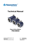
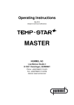
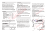
Model 960
Installation Instructions
Parts List
Service Instructions
Bulletin 73262
Model 960 Installation Instructions
Three connections are required
at the centrifuge:
1. Oil Inlet (1⁄2-in. NPT Female Pipe) — Unscrew plastic shipping plug. Run #8 hose from point of highest pressure.
2. Oil Outlet (1⁄2-in. NPT Female Pipe) — Unscrew plastic
shipping plug. Run #8 hose to crankcase above oil level.
3. Air Inlet (1⁄4-in. NPT Female Pipe) — Unscrew plastic
shipping plug. Run #4 hose from any convenient point
on air supply to air valve cartridge inlet. Do not remove
cartridge — loss of cartridge seal will damage unit.
CAUTION — Route hoses to clear exhaust and all moving
parts and fasten securely. Be certain pressure oil supply is
to OIL IN port on side of centrifuge and return to crankcase
is from OIL OUT port on bottom. Do not remove full-flow
filters. Use the Spinner II centrifuge only as a bypass oil
cleaner. Remove any previously installed bypass filters
prior to installation of the Spinner II, and block ports where
necessary.
Spinner II/960
Net Weight 11.02 lb (5.0 kg)
Dimensions in
inches (mm)
4.44 (112.71)
To remove bowl
8.51 (216) max.
Clamp can be rotated 360°
7.0
(178)
12.96
(330)
6.81 (173)
7.35 (186.5)
3.94
(100)
1/2-in.
NPT
Oil In
Oil In
.79 (20)
.40 Ø
(10.16)
4.72
3.00 (120)
(76)
5.47
(139)
.63 (16)
Oil
Out
.57 (17)
Detailed Information Available
For optimum performance of your centrifuge, specific
installation drawings for almost any diesel engine can
be requested from your distributor.
General Instructions
4.25
(108)
5.51
(140)
.63 (16)
Air
In
1/4-in.
NPT
1/2-in.
NPT
Frame rail
or bracket
1.96
(50)
4.34
(110)
Frame rail
or bracket
3/8-in. (10 mm) Grade 5
bolts and nuts — tighten
to 23 lb-ft (26.5 N-m)
Not supplied
Washer
Washer
Mounting hole
13/32-in. .406 (10.3)
Noise isolator installation
Dirty Oil Supply to Centrifuge Oil Inlet
Pressure Tap on Engine — Most engines, including the
latest models from Cummins, Caterpillar, DDC and Mack,
provide a 3⁄8-in. or 1⁄2-in. port to supply an auxiliary device.
Avoid using end-of-gallery supply points such as the
pressure gauge tap.
Clean Oil Outlet Return to Crankcase
Return Opening in Crankcase — Most engines have
a 1⁄2-in. or larger oil return opening provided in the
crankcase wall. If unrestricted, this is an ideal oil
outlet line connection point.
Special Return Problems — If there are no available
drain openings, it may be necessary to drill and tap an
inspection plate. Remove the plate before modification
and avoid directing the return flow directly onto moving
parts. Request assistance from your distributor.
Mounting Location
Install Vertically ±10°. The frame rail is the preferred
location for mounting the centrifuge. A Spinner II Part
70845 spacer is available to facilitate inside frame rail
mounting, requiring only two holes in the rail. Check
with manufacturer before drilling. Bulletin 71294 contains
a drilling template. Additionally, a Spinner II Part 71421
No-Drill mounting bracket kit is also available. Use this kit
when installation will not permit drilling of the frame rail.
The Spinner II centrifuge is a high-speed device and is
provided with noise isolators for operator comfort, which
must be installed as shown above. Care should be used
to prevent metal-to-metal contact with the frame or body,
which might result in unnecessary noise or vibration. The
cover clamp can be rotated to any convenient position
and tightened by hand only.
Air Supply
2.6
2.4
2.2
2.0
1.8
FLOW
1.6
1.4
8000
1.2
7000
1.0
.8
6000
SPEED
5000
.6
4000
.4
3000
.2
2000
10 20 30 40 50 60 70 80 90
Oil Pressure – psig
SAE 30 Oil at 167°F / 75°C
Turbine Speed rpm
Oil Flow U.S. gpm
Air for the control mechanism can be taken from any convenient place on the vehicle air system where there is a
constant supply of air, preferably from the dry tank. 1⁄8-in.
nylon tubing is sufficient or #4 hose can be used if preferred. Air pressure can vary from 35 to 125 psig. No regulators, valves or control devices are required. The Spinner
II control automatically shuts off the air supply when the
engine stops. 0.02 SCFM air consumption is almost too
small to measure.
Note: The control mechanism can be operated on
bleed air taken from the turbocharger manifold if compressed air is not available. The standard air valve must
be replaced by Part #72137 low-pressure air valve cartridge which includes a pre-filter Part #71246. Request
Bulletin 86.020 for details.
Model 960 Parts List
Item
Description
Part number
Only items shown with part numbers are available. Bold denotes assembly
Centrifuge, Spinner II/Model 960 complete ............................ 73190
Service kit, clean bowl (1 each items c, l and n) ................... 73187
a
Cover ................................................................................................ 73191
b
Clamp, cover to base ................................................................... 71266
Tee bolt and knob clamp ............................................................. 71270
● c
Seal-cover, nitrile ........................................................................... 71240
Cover assembly ............................................................................ 73195
h
Nut-centrifuge bowl ...................................................................... 73239
k
Bowl-centrifuge .............................................................................. 73196
● l
Insert, paper-centrifuge bowl (pkg. of 50) ................................. 73165
● n
Seal-centrifuge bowl, nitrile ........................................................ 73189
m
Baffle/screen-centrifuge ............................................................... 73197
s
Body-centrifuge turbine ............................................................... 73194
d
Centrifuge turbine assembly .................................................... 73192
(includes items h, k, l, m, n and s)
e
Housing assembly ........................................................................ 73188
g
Control mechanism assembly .................................................. 70675
Screw, hex head cap-control mechanism ............................... 70673
M10 x 35 mm (available locally)
Seal-control mechanism (Viton姞) ................................................ 70996
Repair kit-control float mechanism ......................................... 71445
■ f
p
Kit-isolator, noise, with washers (set of 4) .............................. 71173
(3⁄8-in. grade 5 bolts and nuts not supplied)
■ q
Cartridge-air valve assembly (includes item r) ................... 70938
(optional assembly for turbo air supply - 72137)
r
Seal-air valve cartridge, Viton ................................................... 70966
Service Cycle ● Whenever bowl is cleaned or replaced.
■ At unit rebuild or when required.
Rev 9/02
Model 960 Service Instructions
Refer to Parts List illustration
1. Shut off engine and allow centrifuge turbine assembly (d) to come to
a complete stop.
2. Loosen handle on clamp (b), disengage tee bolt and remove cover
(a), using coin in gap to separate cover from housing.
3. Partially withdraw centrifuge turbine assembly (d) from the housing (e)
and allow oil to drain from nozzles (o) before removing completely.
Hold the centrifuge turbine assembly in one hand and loosen knurled
bowl nut (h) several turns until the face of the nut projects beyond the
bronze bushing face. Carefully separate centrifuge bowl (k) from turbine body (s) by striking the face of the nut (h) with the palm of one hand
while holding the bowl in the other. Do not strike the nut or the bushing
with or against a hard surface or damage will result. Finish removing
the nut and then remove the bowl and baffle/screen (m).
4. Simply replace the dirty centrifuge bowl with a new one or carefully
remove the dirt cake from the bowl (k) using a wooden spatula or
other non-damaging tool. Wipe out bowl with solvent. Note: To save
time in cleaning, an optional die-cut Bristol paper insert (l) is available
as a service part and may be installed to allow the compressed cake
to be removed quickly.
5. Wash and clean baffle/screen (m) and turbine body (s), removing and
discarding black Nitrile bowl seal (n).
6. Inspect top and bottom bushings of centrifuge turbine body (s).
Replace turbine assembly if bushings show severe wear. Reassemble:
Place baffle/screen (m) over stem of turbine body and seat evenly over
shoulder on base. Install bowl seal (n) in recess in outer edge of turbine base. Slide a new centrifuge bowl (k) over stem and seat uniformly
over bowl seal. Install and tighten knurled bowl nut (h) securely, using
finger pressure only.
7. Inspect housing assembly (e) paying special attention to journal areas
of spindle. Replace housing if damaged.
Trouble-Shooting
Centrifuge removes too little dirt
Check for Proper Operation
Warm up engine and then bring engine to normal speed for one
minute and immediately shut it down. If the Spinner II unit is working
correctly the turbine can be heard spinning. As with any high-speed
device, it may go through momentary periods of vibration as it passes
through critical speeds while slowing to a stop. This is normal. If the turbine is not spinning or if vibration is severe or continuous at all speeds,
an error may have been made in assembly. Repeat steps 1 to 10, paying special attention to the proper seating of baffle/screen (m), the bowl
seal (n) (Step 6) and the control mechanism (Step 9). If vibration persists,
substitute a different centrifuge turbine assembly (d).
If the turbine is spinning properly, the centrifuge is doing its job of
removing harmful abrasive dirt regardless of the amount of deposit
found in the bowl. The visible deposit is largely soot and its thickness
will vary from 1⁄16-in. to completely full depending on oil type, oil change
interval, engine type and condition, and operating conditions. Oil additive package design will affect soot size and thus the amount of carbon
and soot collected in the bowl.
Control air valve problems
Float valve flows air constantly or not at all, up or down.
Air tank bleeds down overnight.
Check Valve (Step 9)
Most air control problems can be repaired without dismounting the
centrifuge by renewing the air valve cartridge (q), making certain that
air valve cartridge seal Part 70966 (r) is in place. A cartridge installed
without the seal will be damaged and will leak continuously. If the float
mechanism is worn or broken, the centrifuge must be disassembled
and repaired with control float mechanism repair kit Part 71445.
Instructions are contained in the kit. Caution: The valve cores in the air
valve cartridge are special, low operating force-type with Viton seals to
withstand hot oil. Do not substitute tire valve cores — replace the entire
cartridge.
Top view with centrifuge removed
DS
Mfg.
date code
To check air valve, with air
supply connected, use hook
at this point under float arm
to raise and lower float. Up,
air on. Down, air off.
3/8 in.
9 in.
Form hook as shown from any stiff wire.
18. Clean and inspect cover (a). Always remove the old cover seal (c),
clean the groove in the housing and mating surface of the cover
and replace with a new black Nitrile seal.
19. Check control mechanism (g) — see diagram above.
10. Install centrifuge turbine assembly (d) on spindle. Be sure it rotates
freely. Replace cover (a), position clamp (b) uniformly over cover
and housing flanges, and tighten clamp handle securely by hand
pressure only.
11. With the engine running, check all connections and joints for leaks.
Oil leaks
Cover Seal
Remove cover (a) and cover seal (c). Clean seal grooves in housing
and mating surface on cover. Install a new cover seal (b) in the housing
groove, replace cover (a), position clamp (b) uniformly over cover and
housing flanges, and tighten clamp handle securely by hand pressure
only.
Body to Control Mechanism Seal
Remove cover and centrifuge turbine assembly. Remove control
mechanism by loosening four cap screws. Discard seal (f) and clean
groove and mating surfaces. Replace seal with a new one and retighten
cap screws alternately to 35 lb-ft torque. It is possible to rotate the body
180° if it is necessary to locate the oil inlet port on the left side. Replace
the seal and retighten bolts. Continue from Step 3 above.
Oil Line Connections
Disconnect leaking hose and remove hose adapter from port.
Clean threads in port and on adapter, and inspect for damage.
Reinstall adapter using a good liquid thread sealant. Reconnect hose.
Sales and Service
Tel:
Fax:
Mail:
713-682-3651 or 800-231-7746
713-681-9702
P.O. Box 920946
Houston, Texas USA 77292-0946
Warehouse: 4405 Directors Row
Houston, Texas USA 77092
Web Site:
www.Spinnerii.com
Made in England by Mann+Hummel (UK) Ltd. Patented worldwide.
®Viton is a registered trademark of E.I. DuPont de Nemours & Co., Inc.
®Spinner II is a registered trademark of T.F. Hudgins, Incorporated.
©2002 T.F. Hudgins, Incorporated. All rights reserved.
Litho in U.S.A. Bulletin 73262/9-02