1
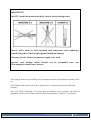
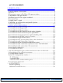
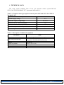
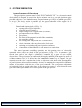
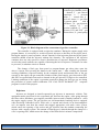
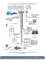
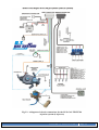
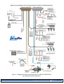
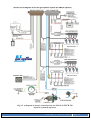
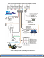
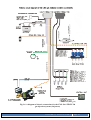
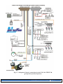
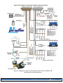
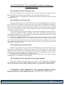
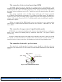
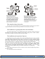
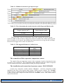
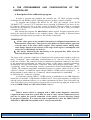
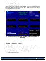
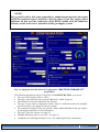
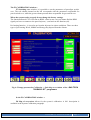
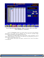
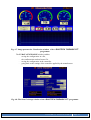
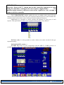
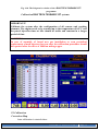
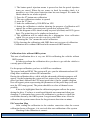
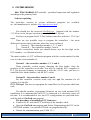
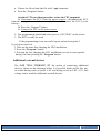
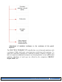
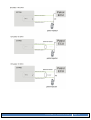
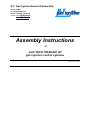
D.T. Gas System General Partnership 20-123 Lublin ul. Lubartowska 71a tel/fax: (+48 81) 744-38-10 e-mail: [email protected] [email protected] Assembly Instructions of GAS TECH 700/BASIC GT gas injection control systems January 2010, Lublin IMPORTANT! The manufacturer does not bear any responsibility for using the device not in accordance with the service manual. The service manual is an integral part of a device and is handed on to its users. It is forbidden to introduce any changes to GAS TECH 700/BASIC GT which may result in losing guarantee rights. Opening of the controller casing or damage of the lead guarantee seal will result in the loss of guarantee rights. IMPORTANT! The controller should be mounted: - AWAY from possible WATER INFILTRATION, - AWAY from EXCESSIVE HEAT SOURCES, - AWAY from IGNITION WIRE, - Perform good electrical connection, - After removing the fuse system enters the gasoline supply, - Do not open during operation of the system. Assembly instructions Page 2 IMPORTANT! The ECU should be mounted with the electric wire pointing down. Electric wires must be well insulated and connectors and conductors secured along their whole length against insulation damage. First-rate electric soldered connectors ought to be used. Injectors and feeding cables should not be assembled near any electromagnetic interference sources. The company bears no responsibility for any damages caused by the improper assembly of the set. The Windows trade-mark used in these instructions is a registered mark of the Microsoft company. The GAS TECH 700/BASIC GT system must be installed only by persons who hold an appropriate license and are instructed by an authorized distributor of the D.T. Gas System. Assembly instructions Page 3 LIST OF CONTENTS 1. TECHNICAL DATA.......................................................................................................... 5 2. SYSTEM OPERATION ..................................................................................................... 6 General purpose of the system ........................................................................ 6 Injectors .......................................................................................................... 7 Gas pressure sensor in the filter of the gaseous phase ..................................... 8 Temperature of the gas reducer ....................................................................... 8 Rotational speed of the engine crankshaft ....................................................... 8 The central unit ............................................................................................... 8 Oxygen sensor’s signal ................................................................................... 9 Controlling gas electrovalves and petrol injectors ........................................... 9 Gas level in the tank ......................................................................................10 3. INSTALLATION DESCRIPTION ................................................................................. 10 The installation of the refueling valve ............................................................19 The installation of the gas tank.......................................................................19 The installation of the gas reducer ..................................................................19 The installation of the controller in the engine chamber .................................19 The connection of the rotational speed signal RPM .......................................20 The connection of oxygen sensor’s signal (lambda probe) .............................20 The connection of the tank’s gas level sensor ................................................20 The connection of gas electrovalves ...............................................................21 The installation of a gaseous phase filter with a distributor ............................21 The installation and connection of injectors ...................................................21 The connection of the evaporator temperature sensor.....................................22 The installation and connection of pressure sensor MAP SENSOR ..............22 The installation and connection of the central unit .........................................23 Power supply connection ...............................................................................23 The installation of fuses .................................................................................23 4. THE PROGRAMMING AND CONFIGURATION OF THE CONTROLLER .............. 234 A description of the calibration program ........................................................24 The Main Menu window ................................................................................25 In the F2 Configuration window -> ..............................................................25 F3 Calibration ............................................................................................27 Correction Map...........................................................................................27 Calibration drive without OBD system. ......................................................32 The emergency password ...............................................................................34 5. SYSTEM SERVICE ...................................................................................................... 35 Software updating ........................................................................................35 Additional external devices ......................................................................... 36 Assembly instructions Page 4 1. TECHNICAL DATA The most crucial technical data of the gas injection control system LPG and CNG “GAS TECH 700/BASIC GT” is presented in the table 1.1. Table 1.1. Technical data of gas injection control system LPG and CNG “GAS TECH 700/BASIC GT” Description Value 12 V Nominal supply voltage Admissible supply voltage range 10 16 V Maximum value of current consumption 7A Minimum value of velocity signal voltage RPM 3V Admissible range of ambient temperature –40 C to +120 C Protection degree IP66 Table 1.3. Description of additional equipment: Description Value Type of engine Petrol spark- ignition combustion engine Types of the petrol injection - simultaneous multi-point - MPI (Multi-Point Injection) - sequential– SFI (Sequential Fuel Injection) from 700 cm3 from 1 to 4 (or 1 to 8) optional from 5 kW Capacity Number of cylinders Cylinder layout Power Assembly instructions Page 5 2. SYSTEM OPERATION General purpose of the system The gas injection system control “GAS TECH 700/BASIC GT” is an electronic control device which is designed to control the fuel-air mixture ratio in a car spark ignition engine provided with one or two lambda sensors. Propane-butane gas (LPG) or methane gas (CNG) is its fuel. The device works in parallel with the petrol controller of the engine and is responsible for controlling the composition of injected fuel-air mixture. Based on the input signals of (Fig. 2.1): opening time of petrol injectors, rotational speed of engine n, output voltage of the oxygen sensor (or sensors), gas temperature in the reducer, gas pressure, the status of the gas/petrol switch of the central unit, the controller controls: the opening time of injection array’s electrovalves , closing /opening of the gas electrovalve (fuel pump), switching on /switching off petrol injection emulators, visualization of the controller’s work status in the central unit. The most important controlling quantities are the opening times of electrically controlled valves which are placed in the gas injectors 10 (Fig. 2.1). The amount of gas flowing into each of the engine’s cylinders is controlled by a group of two coupled electrovalves. The gas injectors are connected with supply manifold of the engine by means of rubber pressure conduits 12. After the valve’s opening, the gas flows to the manifold via a rubber conduit where it is sucked into the combustion chamber by the engine. The gas controller sets the valve’s opening time in the gas injectors on the basis of the opening times of petrol injectors and correction quantities. Its aim is to maintain the composition of the burnt mixture in accordance with the one of the petrol controller. The overpressure adjustment of gas which feeds the engine takes place in the reducer/evaporator 5, whilst injected stream gas control takes place thanks to the valves placed in the gas injectors. Assembly instructions Page 6 1 – engine, 2 – oxygen sensor in exhaust gas (lambda probe), 4 – throttle, 5 – gas reducer/ evaporator, 6 – pressure sensor, 7 – central unit, 8 – gas level sensor, 9 –gas filter of gaseous phase with a distributor, 10 – gas injectors, 11 – catalyst, 12 – gas injection conduits, 13 – petrol injectors, EG1 and EG2 – gas electrovalves, P – petrol pump Figure 2.1. Block diagram of the connections of gas flow controller The controller is equipped with an injection emulator. During the engine supply with propane-butane, it is necessary to switch off petrol injectors so that they do not inject petrol. During the engine’s petrol operation, electric impulses of the injection generated by the petrol controller should reach the injectors without any obstacles. The operation of the injection emulator does not only consist in electric disconnection of injectors. Diagnostic procedures saved in the petrol controller are capable of detecting the lack of injectors’ resistance. In order to prevent it, a substitute circuit is formed. The change of fuel type from petrol to propane-butane gas takes place upon the driver’s request, after pressing the button in the central unit 7. After reaching the assumed working conditions (expressed mainly by the rotational speed and thermal state of the gas system) by the engine, the gas controller switches off the petrol supply, gas electrovalves EG1 and EG2 are opened and electrovalves situated in the gas injectors 10 begin to be controlled. Limiting conditions of the engine’s operation required to change the fuel type are set during the procedure of system control calibration. The “GAS TECH 700/BASIC GT” computer program is used for this purpose. Injectors Injectors are designed to install sequential gas injectors in automotive vehicles. This equipment makes provision for the evaporated gas feed into the engine. After going through the filter with a distributor, gas supplies particular injectors and is suitably batched to reach the engine supply system. The gas injectors are electromechanic batching devices equipped with electrically controlled valves. Each valve is opened and closed via an electromagnetic coil. An impulse sent from the control unit triggers appropriate coils with a valve system, which causes the opening of the socket and gas injection into the conduits connecting the injector with a supply system. The amount of flowing gas is altered through the change of a valve’s opening time, which causes the change of the burnt fuel-air mixture composition. Assembly instructions Page 7 The system also works with such injectors as: - Bluetech Pegas Matrix Valtek Keihin Magic DTi Gas pressure sensor in the filter of the gaseous phase The gas pressure sensor measures relative pressure in the gas filter. The sensor is located in the filter of the gaseous phase. Pressure is measured against atmospheric pressure and it is needed to determine gas volume flowing through gas injectors in a time unit. Temperature of the gas reducer A PTC resistance sensor is used to measure the temperature of the gas reducer. Information about temperature value is needed to switch the engine supply from petrol to gas, which happens at a specific temperature. Rotational speed of the engine crankshaft For the estimation of engine crankshaft rotational speed n, the gas controller uses the RPM rotational speed signal transferred from the ignition circuit to the petrol controller. This is a rectangular wave voltage signal with the frequency dependent on the type of ignition system. The central unit The controller controls the gas mixture composition which supplies the engine automatically. The driver can only change the type of feeding by switching the central unit. The central unit (Fig. 2.2) installed inside a car acts as a petrol/gas switch, and the indicator of gas level in the tank and informs about the kind of fuel a car is supplied with. The central unit is equipped with: petrol /gas switch, six diodes informing about the gas level in the tank, diodes informing about the device’s work mode (B - petrol, G – gas) Figure 2.2. The cabin central unit: 1 – petrol/gas switch (B/G), 2 – diodes signalling gas level in the tank, 3 – diode signalling the petrol supply, 4 – diode signalling the gas supply. Assembly instructions Page 8 The petrol/gas switch enables petrol-to-gas and gas-to-petrol changeover. After pressing the switch, the controller is introduced into the mode change of fuel supply. Gas-to-petrol switching and vice versa does not result in an instant change of supply type. The controller changes petrol-to-gas supply only after reaching the rotational speed memorized by the gas injector (e.g. 2000 rotations/min) and an appropriate temperature (e.g. 20˚C). No additional requirements need to be satisfied during gas-to-petrol changeover. It follows immediately after pressing the switch in the central unit On the top of the central unit there are diodes which inform a driver of the gas level in the tank. The flashing of all green diodes means that the tank is full. The single lighting of the red diode signals the reserve fuel level. Table 2.1. The modes of the system operation The modes of the system operation Automatic Gas Petrol The status of signalling diodes in the central unit G (gas) - green B (petrol) - red blinking no lighting lighting no lighting no lighting lighting The three modes of the system operation are signalled by the diodes lettered G (green) and B (red). They follow each other when the switch in the central unit is pressed. After turning the key in the ignition switch, the central unit changes over to the automatic mode - the diode (G) starts to blink waiting until the moment when the gas-supply working conditions described earlier are fulfilled. When that moment comes, the green diode starts to burn in an uninterrupted manner and the system changes over to the gas supply mode (if the conditions are not fulfilled it is possible to force the system changeover by pressing the switch in the central unit). The pressing of the switch in the central unit will result in the changeover into the petrol supply mode. The red diode (B) lights up while the green diode (G) turns off. As soon as the central unit switch is pressed again the installation returns to the automatic mode. If the switch of the central unit is pressed longer, sound signals sent by an internal buzzer are on/off. The conditions in which the central unit issues sound signals can be set up in the Configuration -> Controller menu. Oxygen sensor’s signal Connect as an option then problems with calibration appear. Do not connect in cars with OBD, by connecting the OBD tester at the same time. The signal is shown automatically. The “O2_IN” voltage oxygen sensor signal (lambda probe signal) located before a catalyst together with the time of petrol injector opening is used to control the opening time of the gas injectors. The controller weakens or enriches the mixture to approximate its ratio to the stochiometric level. The voltages of oxygen sensors vary according to their types in the range : 0 1 V; 1 0 V; 0 5 V; 5 0 V; 0.8 1.6 V.. Controlling gas electrovalves and petrol injectors The controller opens and closes electrically controlled gas inflow valves depending on the working mode (petrol/gas) as well as switches the injectors’ emulator on or off. After switching over to gas supply, the petrol supply is switched off and two gas electrovalves are opened: in the gas multivalve as well as the electrovalve which is assembled in the vicinity of the gas reducer. During gas-to-petrol switchover, the gas valves are closed and the petrol injectors’ control is brought back. Assembly instructions Page 9 Gas level in the tank The gas level in the tank is determined on the basis of the voltage value of the resistance sensor installed in the multivalve which is an element of the gas tank (see assembly instructions of the hallotron sensor). 3. INSTALLATION DESCRIPTION Installation schema for the GAS TECH 700/BASIC GT system. Assembly instructions Page 10 Fig.3.1. A diagram of electric connections for the LPG BASIC GT injection system (4 injectors) Assembly instructions Page 11 Fig.3.2. A diagram of electric connections for the LPG GAS TECH 704 injection system (4 injectors) Assembly instructions Page 12 Fig.3.3. A diagram of electric connections for the LPG GAS TECH 706 gas injection system (6 injectors) Assembly instructions Page 13 Fig.3.4. A diagram of electric connections for the LPG GAS TECH 708 injection system (8 injectors) Assembly instructions Page 14 Fig.3.5. A diagram of electric connections for the CNG BASIC GT gas injection system (4 injectors) Assembly instructions Page 15 Fig.3.6. A diagram of electric connections for the CNG GAS TECH 704 gas injection system (4 injectors) Assembly instructions Page 16 Fig.3.7. A diagram of electric connections for the CNG GAS TECH 706 gas injection system (6 injectors) Assembly instructions Page 17 Fig.3.8. A diagram of electric connections for the CNG GAS TECH 708 gas injection system (8 injectors) Assembly instructions Page 18 GAS TECH 700/BASIC GT systems should be installed according to the following instructions: The installation of the refuelling valve Install the refuelling valve at a distance not less than 70cm from the exhaust system. Make a hole 54 in the bumper and fasten the valve using bolts included in the set. Another method is to suspend the refuelling valve under the bumper using the bracket included in the set. The installation of the gas tank Install gas tank using a rack. Drill holes in the car body through the holes in the rack. Next, protect the holes against corrosion and screw down the rack using bolts and washers. Screw down the gas tank to the rack using clamp hoops. Drill two holes 27 for ventilation and protect them against corrosion. Those holes cannot be located at a distance less than 35 cm away from the exhaust system. Insert bushes to the holes and mount them using sheet metal screws included in the set. Screw down the casing and the multivalve to the gas tank using bolts included in the set. Connect the multivalve with the refuelling valve using a 8 conduit using brazen bolts and clamps included in the set. The conduits between the floor and the multivalve in the boot compartment are led in the ventilation duct. Fasten the toroidal tank to the floor using bolts and washers included in the set. Drill holes in the floor through the holes in the cylinder and protect them against corrosion. Drill a 52 ventilation hole through the holes in the cylinder. Mount the ventilation ferrule using sheet metal screws. Next, screw the cylinder down with bolts. Screw the multivalve down with the bolts included in the set. The installation of the gas reducer Install the gas reducer using two sheet plates. Mount the gas reducer and the gas valve in the engine compartment in a location far away from a direct heat source (the exhaust manifold). Select a location to mount the gas reducer which is optimal to connect the gas reducer with the engine cooling system. Drill holes and protect them against corrosion. Next, screw down the gas reducer using bolts included in the set. Connect the gas reducer to the cooling system using T-pipes and water conduits included in the set; secure them by clamp hoops. The installation of the controller in the engine chamber Install the controller far away from any sources of electromagnetic disturbances (e.g. an ignition coil), and from high temperature sources (e.g. the engine’s exhaust manifold), and at a safe distance from any tanks containing liquids (e.g. cooling fluid equalizing tank.) ATTENTION VERY IMPORANT: The controller should be always mounted with the sockets pointing down !!!!!!!!!!!!!!!!!!!!!!!!!!!!!!!!!!!!!!! Assembly instructions Page 19 The connection of the rotational speed signal RPM The RPM signal pin may be detected by a voltage tester or an oscilloscope. The frequency of the impulse transmitted to the petrol controller increases together with the engine rotational speed and so does the blinking frequency of the voltage tester and the frequency of the signal on the oscilloscope screen. It is advised to take the signal pin from the petrol computer. The voltage amplitude value of RPM signal within the 12V limit is defined as a STRONG signal whilst the one within 2.5V is defined as a WEAK signal. The RPM wire ought to be put far away from high voltage conductors and any electromagnetic interference sources. If the signal is lower than 2,5 V, an RPM amplifier must be additionally installed – available as an option. When you cannot find the RPM signal in new cars you have to try to connect to the petrol injector (-) and activate the function (60) like in the F6 window – admissible CUT OFF time to RPM. The connection of oxygen sensor’s signal (lambda probe) OPTION do not connect the lambda probe. Connect only when problems at calibration appear. Never connect the lambda probe by calibration with OBD – the signal is shown automatically. In order to connect the oxygen sensor with the gas controller, the probe’s signal wire needs to be found, cut and soldered to the controller’s wire lettered O2_IN (violet). Then the gas controller reads the voltage value from the lambda probe and wide range lambda sensor. The connection of the tank’s gas level sensor The signal wire of the gas level resistance sensor should be soldered to the gas controller’s wire lettered LPG_LEVEL (white) (see the assembly instructions of the hallotron sensor). black - ground green - signal red - (+12V) from electrovalve Fig.1. A view of the hallotron sensor Assembly instructions Page 20 Hallotron sensor Hallotron sensor Electrical connector Electrical connector Float Float Fig. 2a Right Lovato valve The turning of the sensor clockwise results in the reduction of the quantity of diodes displayed on the panel, while the turning of the sensor anticlockwise results in the increase of the quantity of diodes displayed on the panel. Fig. 2b Left Lovato valve The turning of the sensor clockwise results in the increase of the quantity of diodes displayed on the panel, while the turning of the sensor anticlockwise results in the reduction of the quantity of diodes displayed on the panel The connection of gas electrovalves The gas electro-valves installed at the gas tank (the multivalve) and near the gas reducer/ evaporator should be connected to the gas controller wire lettered E_LPG (blue ) The installation of a gaseous phase filter with a distributor The gaseous phase filter is to be installed between the evaporator and the gas injectors according to the flow direction marked on the casing, using pressure rubber conduits. The connectors ought to be protected with metal band clamps. The installation and connection of injectors Install the injectors in the vicinity of the suction manifold and locate it as far as possible from high-voltage conduits. Drill holes and screw down brazen ferrules (diameter 4mm) at the ends of supply manifold, near the engine’s inlet valves, so the gas will flow through them. Decline the main axes of the ferrules in the direction of the throttling valve and make an acute angle of about 75 ° against the collector. Connect the pipes with the ferrules of the injector electrovalves using rubber pressure conduits (see Table 3.2). The connectors ought to be protected with metal band clamps. The length of the rubber conduits which connect injectors with supply manifold should be as short as possible. Connect the harness of supply and control conduits of the gas controller terminated in a 6-conduit plug with the injectors. In the outlet of the injector you have to mount a nozzle, which will adjust the gas flow to the engines demand. For choosing the nozzle use table below. Assembly instructions Page 21 Table 3.1. Method of selection of gas injectors type: Table 3.2. Way of mounting the nozzles injection rail in Pegas and Matrix rails: Engine capacity [cm3] Nozzle diameter [mm] to 1600 2,1 1600 – over and turbo 4,0 The given table is only for information. When after mounting the nozzles the car works not stable on idle one has to change the nozzles for smaller ones. When under big load the car switches over to petrol ( the opening time of gas injectors is to big) one has to change the nozzles for bigger ones or don’t use them at all. Table 3.3. The suggested diameter of rubber hoses. Location Reducer - dispenser Dispenser - Injector Injector - manifold MAP sensor - dispenser Inner diameter [mm] Ø 13 Ø8 Ø5 Ø4 The connection of the evaporator temperature sensor The signal of the gas temperature sensor in the evaporator is used to determine the time of petrol to gas switch-over. The temperature sensor installed in the gas reducer/evaporator is to be connected with the conduit marked TEMP_R of the gas controller. The installation and connection of pressure sensor MAP SENSOR Connect the connection conduit marked “Pressure” with the connection conduit installed in the filter of the gaseous phase using a rubber pressure conduit. The ‘Vacuum” ferrule must be connected with the atmospheric air. However, it is necessary to mount a rubber conduit with a length of around 5cm on the “Vacuum” ferrule. That conduit must be directed downwards. Assembly instructions Page 22 The installation and connection of the central unit The central unit should be installed inside a vehicle, at an easily accessible location and should be visible from the driver’s seat. After the control unit is mounted, the harness of wires should be connected with a four-conductor square-cross section plug. Power supply connection For safety, the power supply should be connected at the end of all installation activities. IMPORTANT! Inspect all electrical connections for any breakdowns (electrical insulation) before power supply is connected. Next, the following devices need to be connected: - the GND (black) cable to the battery negative terminal (-). - the +12V controller supplying cable (red) with the battery positive terminal (+) The installation of fuses Finally, the car’s flat-fuses are installed in the sockets of the power supply cables and electric valves (in accordance with the assembly diagram). Assembly instructions Page 23 4. THE PROGRAMMING CONTROLLER AND CONFIGURATION OF THE A description of the calibration program In order to program and configure the controller, the “GT 700S” program working in Windows™ and Windows 98 SE operating system or its later version is required. To program and configure the drivers for GT 700S, the software „GAS TECH 700/BASIC GT” (version 2.21.23 and latest ones) operating in Windows™ are used. As for PC software, Windows 98 SE or its later version is required. Firmware, which is a program loaded to drivers' memory, is common for all versions of drivers (4- and 8- valves, too ) and it is marked as 1.50.02. After starting the program, the Main Menu window appears. Program operation can be carried out using the keyboard or the computer mouse. After pressing a function button or clicking on the right screen key button, a sub-window is displayed. IMPORTANT: All the values given in the assembly instruction of configuration parameters are demonstration values only. Their precise value differs in various models, types and even the parts of the same vehicle (engine). Their optimal values, among many other things, depend on the capacity or the stage of the engine’s consumption, and need to be set individually for each car. The images illustrating the functioning of the program may differ from the delivered program due to the version. The status of the controller connection is displayed in the program main window as the text string “Connected” when establishing communication or as “An error of the COM port” in the case of failure. The connection status is symbolized in particular windows by the colour of the bottom bar background on which the values of the engine operation parameters are displayed. The blue colour means “Connected” status, while the grey colour stands for “Connecting” status. The same thing concerns a connection with the board diagnostic OBD II / EOBD. The computer programme automatically retries to connect which can be set in the “Options” window. A connection status with the OBD II / EOBD system is displayed in the programme’s main window as “Connected” when communication is established or as “Disconnected ” in the case of failure. A connection with the OBD II / EOBD system is established via an OBD diagnostic connection via an OBD – USB interface available at D.T. Gas System branches. A connection with the system mentioned allows you to obtain information on Short Term Trim and Long Term Trim values of a petrol injection correction previewed in the top right part of the screen in the CALIBRATION and VISUALISATION windows. NOTE: When a motor vehicle is equipped with a OBD system diagnostic connection, a signal with data from that system must be used to carry out the calibration process and also to update the general estimation of the quality of petrol injection control by the petrol controller. It is connected with a requirement to have the OBD ELM 327, AMX 530 or OBD MD 100 available at D.T. Gas System branches. Assembly instructions Page 24 The Main Menu window In the “MAIN MENU” window there are keys used to navigate between different subwindows of the program. Additionally in the window are displayed, the connection status with the controller and the on board diagnostic system OBD II / EOBD as well the version and type of the attached controller 4-6-8 cylinders. Fig. 4.1. Image presents the window of the Main Menu “GAS TECH 700/BASIC GT” programme The assembly diagram of the system is displayed after pressing the F1 key. In the F2 Configuration window -> F2 Engine the following can be set: The type of the oxygen sensor (lambda probe) see page 9 and 19. The level of the rotational speed signal, RPM see page 8 and 19. The configuration of the rotational speed measurement - choosing the number of cylinder and coils for getting the correct RPM reading. The type of injection system of the petrol engine see page Engine’s cubic capacity. Turbo charging of the engine. Assembly instructions Page 25 NOTE! For a vehicle with a fuel semi sequential or simultaneous injection the signal of RPM rotational speed should be directly taken from the engine speed indicator. In this case the connection of the RPM conduit with the induction coil may result in incorrect operation of the gas supply system. Fig. 4.2. Image presents the menu of Configuration “GAS TECH 700/BASIC GT” programme The following parameters can be set up in the F2 CONFIGURATION you can set: The type of fuel supply (LPG or CNG), The type of gas injection rail or injectors Bluetech, Valtek, Pegas etc. The diameter of a nozzle installed in the injectors The type of gas reducer temperature sensor. Only if a different reducer the standard one was used you can change the factory settings, The connection method of the gas pressure sensor MAP SENSOR in the gas reducer (to the supply manifold or to the atmosphere), The type of gas level sensor, see page 19, Whether the display filter is on or off – see page 20, Conditions for switching the buzzer on (i.e. the sound signal of the central unit). Assembly instructions Page 26 The F3 CALIBRATION window-> F7 Switching over window, it is possible to set the parameters of petrol/gas switchover. The red column situated on the left corresponds with the parameters responsible for petrol switch-over, while the green column presents those responsible for gas switch-over. When the system works correctly do not change the factory settings. The function allowed CUT OFF time to RPM –when in new cars you cannot find the RPM signal you have to connect to the petrol injector (-) and activate the function (60). Pre hearing function – it is used to pre heat the injectors in winter conditions. There are three types of pre heating: Week, Middle and Strong, they depend from the climate. Fig. 4.5. Image presents the Calibration -> Switching-over window of the “GAS TECH 700/BASIC GT” programme In the F3 CALIBRATION window -> F8 Map of corrections allows for the system’s calibration. A full description is available in the System Calibration paragraph. Assembly instructions Page 27 Fig. 4.6. Image presents the Calibration -> Map of corrections window of the “GAS TECH 700/BASIC GT” programme In the F4 Visualization window, the current values of the most crucial quantities characteristic of the engine work are displayed. We can switch-over petrol/gas supply by pressing the central unit’s button displayed on the screen. IMPORTANT: F6 „Save to file” placed in this window, makes it possible to save all major working parameters of gas system to file. Make the save during driving. The save is active when the field changes color to red. When problems with engine work appear send the file by e-mail to the address: [email protected] Assembly instructions Page 28 Fig. 4.7. Image presents the Visualisation window of the “GAS TECH 700/BASIC GT” programme The F5 DATA EXCHANGE window enables: · saving the configuration in a file, · the configuration readout from a file, · saving the configuration in the controller. · going back to the settings of the controller applied by the manufacturer Fig. 4.8. The Data Exchange window of the “GAS TECH 700/BASIC GT” programme Assembly instructions Page 29 IMPORTANT Press the “Store in ECU” button and set the controller’s password to avoid losing the controller’s settings in the case of power supply failure. The password must include 8 characters and will be required at every attempt to connect with the controller. The F6 DIAGNOSTIC window enables the user to conduct active tests of the gas electro valves located in the multi valve, the evaporator and the injectors. It also facilitates the operation check of the electro valves in the gas container and petrol injectors. Additionally it is possible to correct expense (the quantity of given gas) of each injector. This option allows to have even expenses of fuel given to every injector. F8 Error codes. It is also possible to read or delete error codes recorded in the gas injection memory. F6 DIAGNOSTIC window -> F9 OBD When there are any connections with the OBD II / EOBD system it is possible to read or delete error codes recorded in the memory of the petrol controller. Assembly instructions Page 30 Fig. 4.10. The Diagnostics window of the “GAS TECH 700/BASIC GT” programme Calibration GAS TECH 700/BASIC GT systems IMPORTANT! Calibrate the system after the configuration of all sensors and working elements. The engine needs to be warmed up to the temperature of 60 °C and the petrol injection times at idle should be stable and constant in a longer period of time CAUTION! In case of assembly of brand new gas installation or even periodical replacement of used injectors for new ones, the calibration procedure should be repeated after the drive of 1000 km mileage appx. F3 Calibration Correction Map Auto calibration is started when: Assembly instructions Page 31 1. The button petrol injection memo is pressed so that the petrol injection times are stored. When the car comes to back for another check it is possible to see if the petrol injection time has not changed. We make the check when the car works on petrol. 2. Press the F7 button auto calibration 3. The auto calibration window is opened 4. press the F7 Start 5. make the calibration by 2500 RPM on LPG 6. during the calibration a window showing the progress of calibration will appear, the red dots represent petrol, green dots represent LPG. 7. On the diagram will be shown a map on petrol (red dots) and LPG (green dots). The points have to be similar to themselves. 8. The calibration will be ended when be a information: Auto calibration ended. Do you want to start the test drive with OBD? 9. Choosing the “No” means the end of calibration. 10. By choosing the calibration with OBD there are two types of calibration: Calibration drive without OBD and with connected OBD interface Calibration drive without OBD system. This sort of calibration drive is very use full for calibrating the vehicles without OBD system.. In order to perform the calibration drive you have to go with the vehicle to a steady part of the road. For the proper calibration you have to fulfill two conditions: The proper load and RPM. The system will give you the information about full filing those conditions with an OK information. During the calibration drive a table with the advanced calibration progress will appear. On the beginning the system will set points of the combustion map on petrol (red dots) and next the LPG map (green dots). On the graphic diagram first will appear points representing the parameters of the petrol map (red) and next the LPG map (green). The points should be as close of themselves as possible. It has to be highlighted that the calibration program collects the points during the drive. You have to avoid rapid throttle movement and often gear changing. To determine how correct the calibration is you have to check the corrections shown by the OBD system: Long trim and Short trim. After the calibration the system cannot show the long trim ant short trim on minus. F8 Correction Map After ending the calibration in the window correction value the correct calibration factor will appear, it is received after auto calibration of the system. Checking if the calibration is correct: Assembly instructions Page 32 Remembering the petrol in injection time (petrol injection Memo) during the work in idle drive on petrol, we switch to LPG and we check if the petrol injection time during work on LPG is similar to the time that was remembered on petrol ( we compare it be looking on the remembered petrol injection time “petrol injection Memo”) When finding some differences on the map: Making the correction value bigger will make the opening time of the petrol injectors shorter when working on LPG, and making it smaller will make the time longer. ADDITIONAL OPTIONS: 1. KB Value – the above value sets the lean degree of the LPG injector line to the petrol injectors regarding to the RPM over 2500. The change of the above factor is possible by +/- 100 units from the auto calibration set by the system. A onetime change can be made by changing the factor by 20 units. The change of this parameter will adjust the cars dynamic, specially by cars with big power. 2. Offset(ms) value – the above value sets how much the LPG injector is moved to the petrol injector in the whole work value. The correction of this value can be made by writing from +3 to -3 units according to individual needs. In is assumed that the basic characteristic of the injectors are enough. The above correction should be made only when the car do not work stable on idle and the correction on the correction value map gives no results. At the end you have to save the data in the ECU with help of the DATA exchange window. Assembly instructions Page 33 The emergency password To do that: 1. Select “I forgot the password” bookmark in the “Enter the ECU password” window, 2. Press the “Generate the key” button, 3. The programme will generate an emergency code, which must be memorized, 4. A one-time emergency password based on the generated code may be obtained from the Customer Service Office or from the Manufacturer’s website, 5. The emergency password obtained allows the user to gain emergency entry to the system. Assembly instructions Page 34 5. SYSTEM SERVICE GAS TECH 700/BASIC GT controller periodical inspection and regulation according to the guaranty book Software updating The up-to-date versions of system calibration programs are available on the manufacturer’s website: http://dtgas.pl/serwis.html. You should use the universal GasTech.exe program with the number 2.21.08 to service the gas injection system by D.T. Gas System. You have to program the D.T. Gas System controllers with the 1.22.01.ep4 input. There are two possible ways to program the controllers – the main difference between then is the time when they were produced: 2. Variant I – The controllers number 1, 2 , 3, and 4 3. Variant II – The controllers number 5 and 6. Which version/boot loader you should choose says the last digit in the ECU number – see illustration below. The main window of „GT” calibration program with the version marked (in this case it is the version number 6). Variant I – the controllers number 1, 2, 3, and 4. Those controller version require changing the boot loader. Only the producer of the controller can do that. You have to send the ECU computer to D.T. Gas System Company to reprogram it with the 1.22.01 code, you have to install the boot loader number 6 on the ECU earlier. Variant II – the controllers number 5 and 6. For this controller versions exists only one ep4 file common for all systems. It is the file GT-1.22.01ep4. You have to reprogram the controllers for all systems which this code. You should actualize (reprogram) firmware on cars with mounted LPG installation. It is important that the ECU is connected to a electricity source all the time. It is recommended to save the ECU configurations on your hard drive with the help of GasTech.exe program. The procedure of actualizing ECU firmware: Connect the PC with the ECU with help of the interface cable. Open the GasTech.exe program and choose Programming the ECU in the OPTIONS window ( or open the DTFash.exe program directly). Choose the communication port (COM 1,2..). Assembly instructions Page 35 Choose the file to load (the file with *.ep4 extension). Press the „Program” button. Attention!!! The accident procedure (when the CPU suspends) 5a. Disconnect the ECU from the power source ( disconnect the ECU from the wiring harness, disconnect the fuse or disconnect the ECU by the battery). 5b. Press the „Program” button. 5c. Connect the ECU to the power source. 2. The programming should end when you see „SUCCESS” on the screen. 3. The ECU is ready for work. If the programming is not successful repeat actions from point 5. If you do not succeed : 1. Take out the main fuse charging the LPG installation, 2. Press the “Program” button 3. Put back the fuse charging the LPG installation (see not to cause sparks) during 30s from pressing the “Program’ button Additional external devices The GAS TECH 700/BASIC GT the option of connecting additional devices, shown on the drawings below. It is possible thanks to the free pin, on which during work on petrol is 0V and during work on LPG +12V. this voltage can be used for additional external devices. Assembly instructions Page 36 Adjustment of emulator resistance to the resistance of the petrol injectors. The GAS TECH 700/BASIC GT controller has a set of internal emulators with a resistance 100Ω, which suits petrol injectors witch about 6 Ω resistance. To adjust the controllers emulators to a different resistance (smaller or bigger) you have to connect an additional resistance (see drawing below), or use and external emulator. Emulators of such type are offered by the companies: PROTEC Digital, KME, AC. Assembly instructions Page 37 Assembly instructions Page 38