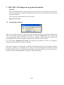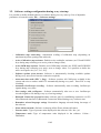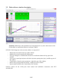
1
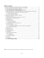
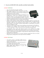
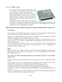
OSCAR-N SAS MINI / PLUS / OBD CAN User manual ver. 1.51 dated 2014-10-23 This instruction, diagrams and training movies can be also downloaded from: http://europegas.pl/en/technical-support/ Table of content 1. Overview of OSCAR-N SAS controllers and their functionalities..................................................3 2. OSCAR-N MINI / PLUS / OBD CAN SAS way of assembling.....................................................6 2.1. OSCAR-N MINI SAS installation diagram.............................................................................6 2.2. OSCAR-N PLUS/OBD CAN SAS installation diagram..........................................................6 2.3. Proper installation of OSCAR-N SAS ECU.............................................................................7 2.4. Selecting proper type of EG2000 GOLD LABEL injector according car's horsepower..........8 2.5. Usage of changeover switch model LED-5 and model LED-7..............................................10 2.5.1. LED-5 model description:...............................................................................................10 2.5.2. LED-7 model description:...............................................................................................11 3. OSCAR-N SAS diagnostic program description...........................................................................12 3.1. Starting the software...............................................................................................................12 3.2. Software settings configuration during every start-up............................................................13 3.3. Main software window description........................................................................................14 3.4. Settings Panel..........................................................................................................................15 3.5. Changeover Panel...................................................................................................................17 3.5.1. Parameters To Gas..........................................................................................................17 3.5.2. Parameters To Petrol.......................................................................................................18 3.5.3. Working and Minimum gas pressure..............................................................................19 3.6. Calibration Panel....................................................................................................................20 3.6.1. Auto-calibration on idle..................................................................................................21 3.6.2. Collecting maps during the drive and calculation of adjustments..................................21 3.6.3. Auto-adaptation feature...................................................................................................23 3.7. Map Panel...............................................................................................................................26 3.8. Corrections Panel....................................................................................................................27 3.9. Advanced Panel......................................................................................................................28 3.10. Oscilloscope Panel................................................................................................................34 3.11. OBD Panel............................................................................................................................35 3.12. Errors/Warnings bookmark...................................................................................................37 3.12.1. Errors list.......................................................................................................................37 3.12.2. Warnings list..................................................................................................................38 3.13. Conditions bookmark............................................................................................................39 3.14. Service..................................................................................................................................40 3.15. Language...............................................................................................................................40 3.16. Loading and saving settings..................................................................................................41 3.17. Firmware update procedure..................................................................................................42 Hint: Click with Your left mouse button on any of above chapters to go to its page. 2/42 1. Overview of OSCAR-N SAS controllers and their functionalities. OSCAR-N MINI SAS • • • • • • • • • • • • Very fast Central Processing Unit 120 MHz. Built-in petrol injection emulator with resistance 100 Ohm. Full feedback diagnostic of gas injectors circuits (system signalizes an error after detecting an circuit intermittence and automatically goes back to petrol). Possibility of: connection and reading the parameters of one Lambda probe -version LS or connection of separate wire from ECU harness to cut-off petrol fuel pump circuit after changeover to gas with programmable time delay -version FP. Possibility of starting the vehicle directly on gas by holding switch button. Feature of filtering petrol injector pre-pulses (extra-injections). Software makes possible to adjust parameters of fuel supply system in very large scale. Besides the correction due the vacuum in the intake manifold, installer can adjust gas dosage regarding to RPM level, gas temperature and gas pressure. It is also possible to adjust mixture dosage for each cylinder separately and possibility of preheating the gas injectors before first changeover to gas. „Exit from cut-off on petrol” feature (from too high gas pressure during cut-off conditions). Calculation of the multiplier value corrections can be done by a single click on the „Calculate adjustments” button in the software after collecting petrol and gas maps. Auto-adaptation feature ensures that during the driving on gas multiplier line is being automatically corrected within desired ranges (tolerance in %) in places on the map where petrol and gas lines are not close enough to each other (works even without connected PC). Feature of „full-injection opening mode” for chip tuned cars with petrol injectors constantly opened during very high loads. Possibility to force gas injector to be opened at minimum opening time value (to avoid not full gas injector opening when too slow injector has been installed). OSCAR-N PLUS SAS • • • All features present in OSCAR-N MINI SAS are included in OSCAR-N PLUS SAS moreover it has all features mentioned below. Possibility of connection and reading the parameters of two Lambda probes at the same time. Separate wire from ECU harness to cut-off petrol fuel pump circuit after changeover to gas with programmable time delay. 3/42 OSCAR-N OBD CAN SAS • • • All features present in OSCAR-N MINI and PLUS are included in OSCAR-N OBD CAN SAS. Moreover it has all features mentioned below. Built-in datalogger circuit activated by holding the switch button during the driving makes possible to register and save to memory all system parameters. Helpful to diagnose a malfunction when the car is out of workshop. Possibility of erasing OBD errors plus monitoring and making corrections of gas injection opening times regarding petrol injection Fuel Trims separately for both Banks for OBD CAN protocols and for older OBDII protocols directly from ECU harness (no OBD adapter necessary). Improvements in SAS controller firmware version 10.100/ software version 1.51 ATTENTION: All new features in OSCAR-N SAS software version 1.51 will work properly only if the SAS controller has been programmed with latest 10.100 firmware version. Software 1.51 with firmware file in version 10.100 included, can be used to update any of SAS controllers with older version of firmware (eg. 0.89 or 10.92). In case of establishing connection with controller having firmware version older than 10.100 via software version 1.51 it is highly recommended to run the update procedure as described in last chapter of this manual. After upgrading controller's firmware from version 0.89 to 10.100 it will be no longer possible to work with that controller with software version older than 1.51 nor downgrading the controller firmware to older version. HINT: When the mouse cursor will be held over a particular software functionality for time period longer than 3 seconds a balloon tip will appear there. It will be containing short description how given functionality works. List of new key features and improvements in SAS controller firmware version 10.100 / software 1.51: 1) RPM signal can be read out directly from the petrol injector (no need to connect RPM signal wire) 2) Gas leakage occurrence is being indicated and registered in ECU's memory when the gas pressure before engine start is lower than the value of "Minimum gas pressure". 3) Automated self-connection via the Bluetooth interface during software start-up. 4) Automatic information about the possibility of upgrading software through Internet. 5) Automatic scaling of calibration map range depending on the maximum injection time achieved. 6) Active „Calibration map” assistant (using the Up and Down keys when mapping, changes the value of the multiplier for actual petrol injection time). 4/42 7) Active „RPM / injection time map” assistant (using the PgUp and PgDown Up Down when mapping changes the enrichment in the active map area). 8) The program automatically starts to record the oscilloscope signals at each start-up. 9) Possibility of introducing parameters of self-defined non-standard gas injectors. 10) Automated "Mazda leaning" feature (when car switches the injection control strategy from Sequential to Semi-sequential). 11) Possibility of mixture extra-enrichment during rapid accelerations. 12) Exit from cut-off on gas through reducing the gas injection time during big pressure growth for a defined number of injection cycles. 13) Possibility of hiding from the end user temporary switchover to petrol. 14) Buzzer signal during switchover between fuels. 15) Protection of multiplier settings after calibration against changes caused by pressing "Calculate multiplier" button. 16) Opportunity to protect controllers settings with a password. 17) Overlapping fuel cycles when switching (for a set number of cylinders cycles are given simultaneously petrol and gas). 18) Integration with vehicles equipped with Start & Stop system. 19) More precise method of petrol and gas maps collection. 20) Support of gas and reducer temperature sensor NTC 6.8 kOhm. 21) More fluent sequential switchover between fuels. 22) Possibility of automated emergency start with gas without need to hold the switch button. 23) Possibility to read and view the controller's settings and to preview oscilloscope from the file without necessity of establishing connection with the controller. 24) Possibility of saving in the controller's memory the size of mounted injector nozzles and five most recent service maintenance inspections. 25) Constantly visible indicator of the collected calibration maps quality in the whole range of engine loads. 26) Support of for new switch LED-7 model with built-in buzzer and plug (no need to solder the harness wiring). 27) Possibility to set separate neutral OBD points for the engine working on idle and at higher RPM. (feature available only in OBD CAN SAS) 28) Support of "inverted" OBD corrections. (feature available only in OBD CAN SAS) 5/42 2. OSCAR-N MINI / PLUS / OBD CAN SAS way of assembling 2.1. OSCAR-N MINI SAS installation diagram 2.2. OSCAR-N PLUS/OBD CAN SAS installation diagram 6/42 2.3. Proper installation of OSCAR-N SAS ECU During the installation of OSCAR-N SAS sequential gas injection system it is suggested for the wire set to point downwards. It is also suggested that it should be placed in such a way to avoid the negative impact of high temperature and humidity. It is highly prohibited to spray ECU box with water jets or expose it to long lasting contact with water. The +12V ignition key red-white wire from ECU harness needs to be connected to the place in which +12V voltage appears from the moment of turning on the ignition key to ACC position, do not drops below +9V during engine cranking and remains stable during all the time of engine's work. Voltage should drop to 0V shortly after turning off the ignition key. It is recommended to check that the circuit of vehicle's element to which we've connected to doesn't became temporarily powered off during engine's work like eg. air-conditioning compressor power supply wire. It is highly recommended to connect +12V ignition key red-white wire from ECU harness into original vehicle's +12V ignition key circuit. 7/42 2.4. Selecting proper type of EG2000 GOLD LABEL injector according car's horsepower The injectors efficiency should be selected in such way so that at low and high engine load conditions the petrol injection opening time on gas should be equal to petrol injection opening time on petrol. Tables given below should help to make right choice. Present type/colour Type A+ (Blue Label) Type A (Gold Label) Type B (Gold Label) Type C (Gold Label) Type D (Gold Label) Former type/colour Type A+ (Blue Label) Type A (Green Label) Type B (Red Label) Type C (Black Label) Type D (Violet Label) Present type/colour Type A+ (Blue Label) Type A (Gold Label) Type B (Gold Label) Type C (Gold Label) Type D (Gold Label) Former type/colour Type A+ (Blue Label) Type A (Green Label) Type B (Red Label) Type C (Black Label) Type D (Violet Label) Nozzle size/mark For LPG Coil resistance HP/cylinder (+/-15%) Engine power range x 4-cyl x 6-cyl x 8-cyl none 1,3 Ohm 40 / 50 / 60 HP 160 ~ 240 HP 240 ~ 360 HP 320 ~ 480 HP none 1,9 Ohm 33 / 42 / 50 HP 132 ~ 200 HP 198 ~ 300 HP 264 ~ 400 HP 1,9 Ohm 30 / 38 / 45 HP 120 ~ 180 HP 180 ~ 270 HP 240 ~ 360 HP 1,9 Ohm 20 / 25 / 30 HP 80 ~ 120 HP 120 ~ 180 HP 160 ~ 240 HP 1,9 Ohm 15 / 19 / 24 HP 60 ~ 96 HP 90 ~ 144 HP 120 ~ 192 HP 2,4 mm (one line) 2,1 mm (two lines) 1,9 mm (three lines) Nozzle size/mark For CNG Coil resistance HP/cylinder (+/-15%) Engine power range x 4-cyl x 6-cyl x 8-cyl none 1,3 Ohm 38 / 45 / 53 HP 152 ~ 212 HP 228 ~ 318 HP 304 ~ 424 HP none 1,9 Ohm 30 / 38 / 43 HP 120 ~ 172 HP 180 ~ 258 HP 240 ~ 344 HP 1,9 Ohm 25 / 33 / 39 HP 100 ~ 156 HP 150 ~ 234 HP 200 ~ 312 HP 1,9 Ohm 15 / 20 / 26 HP 60 ~ 104 HP 90 ~ 156 HP 120 ~ 208 HP 1,9 Ohm 10 / 15 / 19 HP 40 ~ 76 HP 60 ~ 90 HP 80 ~ 152 HP 2,4 mm (one line) 2,1 mm (two lines) 1,9 mm (three lines) You might also use “EG2000 Assistant” available in OSCAR-N SAS software. 8/42 Remarks For pressure 0.8/1.0/1.2 bar (under max load) For pressure 0.8/1.0/1.2 bar (under max load) For pressure 0.8/1.0/1.2 bar (under max load) For pressure 0.8/1.0/1.2 bar (under max load) For pressure 0.8/1.0/1.2 bar (under max load) Remarks For pressure 1.3/1.5/1.7 bar (under max load) For pressure 1.3/1.5/1.7 bar (under max load) For pressure 1.3/1.5/1.7 bar (under max load) For pressure 1.3/1.5/1.7 bar (under max load) For pressure 1.3/1.5/1.7 bar (under max load) In case of using standard valve type injectors like RAIL IG1 You can use the “Nozzle calculator” available in OSCAR-N SAS software. Attention: Algorithm assumes that reducer's differential pressure has been set at 1 bar (for LPG reducer) or 1,8 bar (for CNG reducer). Calculated values are only approximate values and it is recommended to start drilling the injector nozzles from a diameter smaller from calculated one by 0,2 mm and depending on the communicates during autocalibration eventually increasing it by step of 0,2 mm. Table given below should help to make right choice. Nozzle diameter [mm] Power for 1 cylinder [HP] 1,8-2 12 – 17 2,1-2,3 18 – 24 2,4-2,6 25 – 32 2,7-2,9 33 – 40 3,0 41 – 48 9/42 2.5. Usage of changeover switch model LED-5 and model LED-7 2.5.1. LED-5 model description: Fuel state diode -the yellow diode located in top right switch corner show current fuel status. It can indicate 5 following states: 1) turned off -system is in petrol mode 2) blinking at 1Hz frequency (once per second) -system awaits for reaching min. reducer temperature 3) blinking at 2Hz frequency (twice per second) -system is in Auto mode and awaits for reaching other conditions required for changeover (eg RPM, preheating injectors etc.) 4) blinking at 4Hz frequency (4 times per second) -system is signalizing an error (eg.“Low gas pressure error”), which is causing instant changeover to petrol 5) emits light constantly -system is in gas mode. Gas level status diodes -4 diodes shows amount of fuel level left in the gas tank. 4 diodes emitting light simultaneously indicate full tank. All 4 diodes turned off means that the gas tank is almost empty. Fuel type selection switch -every single press of the button changes the type of selected fuel. For an emergency start of gas -without usage of petrol (eg. when the petrol fuel pump has been damaged) it is necessary to: 1) press and hold the switch button before starting the engine, 2) move the ignition key to ACC position, 3) wait for opening of solenoid valve, 4) start the engine on gas, 5) release the switch button. Attention: In OSCAR-N OBD CAN SAS pressing and holding the button for 5 seconds during driving on petrol or gas will enable/disable registering the system data parameters to the controller memory. Later on recorded parameters might be downloaded to the PC with diagnostic software. 10/42 2.5.2. LED-7 model description: LED-7 switch model works similar as LED-5 model. Main differences are: 1) Buzzer is incorporated into LED-7 switch. 2) Red diode located in bottom right corner of switch is switched on when buzzer is active. 3) Red reserve diode located on bottom left corner is being switched on when all 4 gas level status diodes are switched off and gas tank is almost empty. 4) There is a 8-pin female plug on the switch back side so there is no need to do any soldering of switch cables to ECU wiring harness. 11/42 3. OSCAR-N SAS diagnostic program description Attention: Before running the software please make sure that You have Java Run-time Environment in version not lower than 7 update 25 installed on Your PC. You can also install it after execution of software installer. You can always download the latest version from: http://www.java.com/ 3.1. Starting the software After first use of the software we will be asked if it should automatically search all available ports and try to establish connection with the controller. If we choose “Autoconnect” the software will try to automatically connect with ECU. If we choose “Cancel” it will be necessary to choose the port manually from the list of available COM ports after each start of the software. If we will enable “Remember last setting” the software will remember our choice for method of connection and will apply it during its every start Autoconnect function is searching for a controller starting from the lowest COM number found in the system. Therefore it is recommended to assign for connected diagnostic interface the lowest possible COM port index to establish connection more quickly. We can always cancel Autoconnect procedure by selecting “Disconnect” and select COM port manually. 12/42 3.2. Software settings configuration during every start-up It is possible to define default behavior of software during its every start-up. List of adjustable parameters is located in menu File → Software settings. • Calibration map autoscaling -Automatical scalling of calibration map (depending on maximum injection opening time achieved). • Active Calibration map assistant -Enables active multiplier assistant (use UP and DOWN keys during map collecting over active point to change value). • Active RPM map assistant -Enables active RPM map assistant (use PGUP and PGDOWN keys during map collecting over active area to change value). It is possible to define the active area square size [1x1; 3x3; 5x5]. • Software updates from internet -Software is automatically checking available updates during every start (active Internet connection required). • Autoconnection mode (ESC = Stop) - Software searches all COM ports available in the system and tries to connect with ECU automatically during every start . Press ESC to stop searching. • Automatic Oscilloscope recording - Software automatically starts recording Oscilloscope signals during every start. • Save settings with oscillogram - Software automatically asks user to save Oscilloscope recorded signals to file during every try of saving settings. • Bluetooth Connection proposal at start -software asks for establishing connection via EG Joker Bluetooth interface by Bluetooth Connection Wizard during every software start. • Remember selected language settings -Remembers language selected during last usage of the software. • Extra-Advanced mode -Software is showing all the Extra-Advanced features. • Pressure units - Type of pressure units displayed in the software: kPa / bar / psi. • Temperature units -Type of temperature units displayed in the software: Celsius / Fahrenheit. 13/42 3.3. Main software window description Attention: Balloon tips with explanation are being displayed every time when mouse cursor is being held over particular function in software window. OSCAR-N SAS diagnostic software main window is composed of: • • • • • • • Main menu bar located on the top of the window. Additional icon bar located below Main menu. Fuel type changeover switchboard with fuel level indication diodes-left top part of the window. List of active petrol/gas injectors with their injection opening times [ms] -middle top part of the window. Visualization of actual system parameters -right side part of the window. Panels with system parameters/settings -central part of the window. System status indication bar -bottom part of the window. Software checks all the COM ports when started and establishes connection with ECU automatically. 14/42 3.4. Settings Panel During every first start of the software please choose the OSCAR-N SAS ECU work mode LPG or CNG (depending on the type of installation in the car). a) set “Fuel type” on which car is running, b) set proper “Cyls. Numbers” -[1...8] -according to amount of petrol/gas injectors connected, c) set proper value of “Cyls. per coil” -[1...8 or RPM div] – how many cylinders we have for 1 ignition coil (to get proper value of RPM). In case of taking RPM signal from camshaft position sensor please select option RPM div in order to divide high frequence of RPM indication in the software to match with real RPM value. d) RPM Divisor -[1...255] -we can divide the RPM signal indication by this value d) set proper value of “RPM signal level” -[5V or 12V or Injector] -usually 12V if signal is taken from ignition coil. Select Injector to take RPM signal from petrol injector wiring (in that case RPM signal wire from the ECU harness doesn't have to be connected) e) set proper “Engine type” [Standard or Turbo] to have proper vacuum range on the map, f) set proper “Gas injectors type” -[H2000/EG2000 type ABC 1,9 Ohm; H2100; EG2000 type A+ 1,3 Ohm; Keihin; BRC 1.9 Ohm; Rail IG1 3 Ohm; Rail IG5 3 Ohm; Magic Jet; Matrix; Matrix HD344/HD544; Rail IG3 Horizon 2 Ohm; Rail IG3 Horizon 2.8 Ohm; Reg OMVL Fast; Valtek 30 3 Ohm; Valtek 30/Rail IG1 2 Ohm; Valtek 30/Rail IG1 1 Ohm; Valtek 34; WGS 11/14/18/24; RAIL IG7 Navajo LP/HP, Tomasetto IT01 2 Ohm, AEB I PLUS 2 Ohm] g) for cars with Injectors controlled by full group strategy (all injectors controlled by single signal) or semi-sequential strategy (injector are being controlled by pairs) change the petrol “Injection type” from “Sequential” to “Full-group” or “ Semi-sequential”. 15/42 h) only for cars with petrol injectors controlled by positive pulse please change the value “Injection controlled by” field from “-” to „+”, i) set proper “Lambda sensor” type if connected, j) select proper type of “Gas level sensor”/pressure gauge installed. If it is necessary to adjust original standard sensor characteristics of level sensor press “Set min” when gas tank is empty and “Set max” when gas tank is full. k) in case of using a “Pressure sensor” / “Vacuum sensor”, “Reducer temperature sensor” or/and “Gas temperature sensor” different from standard ones (ABS400kPa and 4.7kOhm type sensors, which are provided with the ECU set and set as default types) please change sensor type in a proper field. l) Switch type -select LED-5 or LED-7 model depending on the type installed, m) “Hide temporary switchover to petrol” - If turned OFF, the LPG/CNG diode blinks during temporary petrol switchover n) “Buzzer sound during switchover” – if turned ON buzzer gives sound during every switchover between fuels 16/42 3.5. Changeover Panel Set desired parameters for system change over “To Gas” and “To Petrol”: 3.5.1. Parameters To Gas • “Min. reducer temp. [C]” -minimum temperature of reducers required for opening to solenoid valve before first changeover to gas. • “Min. changeover RPM” -minimum value of engine RPM required for the controller to changeover to gas. • “Changeover time -Cold Engine [s]” -additional time period added to “changeover to gas” time. This extra time is being counted from moment of opening the solenoid valves if reducers temperature is lower than “Hot engine” temperature value (default: 50 C degree). • “Changeover time -Hot Engine [s]” -additional time period added to “changeover to gas” time. This extra time is being counted from moment of opening the solenoid valves if reducers temperature is equal or higher than “Hot engine” temperature value (default: 50 C degree). • “Changeover delay per cyl. [s]” -time delay between changing over subsequent cylinders from petrol to gas. In example: when this parameter is set at 0.2 [s] the complete change over to gas of a 4-cylinder engine from gasoline to gas will last 4*0.2[ms]. When this parameter is set to 0 [ms] all the cylinders will changeover to gas / petrol at the same time (recommended value for full-group controlled cars). 17/42 • “Changeover simultaneously” -feature of forcing all cylinder to changeover simultaneously during first autocalibration changeover Attention: For full-group controlled cars please remember to set Changeover delay per cyl. [s] to “0.0” s. and Changeover simultaneously to “ON” before running auto-calibration. • “Remember emergency start state” - remembers the state of emergency start on LPG/CNG, and repeats it without need of holding switch button pressed during start. • “Fuel overlapping cycles” - during first switchover to gas for that number of cycles engine will be injecting gas and petrol simultaneously (gas pressure must be lower than 100kpa!). • “Enable Start & Stop” -function required for proper work with vehicles equipped with Start and Stop system. 3.5.2. Parameters To Petrol • “Max. RPM” -maximum value of engine's RPM at which car can still run on gas. If RPM value will be higher than this value the car will changeover to gasoline. When the RPM will fall back below this value the car will go back to gas mode. • “Max. load value [ms]” -maximum value of petrol injection opening time at which car can still run on gas. If petrol injection time value will be higher than this value the car will changeover to gasoline. When the petrol injection time will fall back below this value the car will go back to gas mode. • “Pressure error time [s]” -time period during which the gas pressure could be lower than the minimum pressure value. If the pressure will drop and stay below this value for time longer than this time period the car will change over to gasoline from “too low gas pressure error”. • “Min. gas RPM” -minimum value of engine's RPM at which car can run on gas. If RPM value will be lower than this value the car will changeover to gasoline. When the RPM will go back above this value the car will go back to gas mode. • “Min. gas Temp [C]” -if gas temperature will fall below that value during driving on gas the system will go back to petrol mode and will not allow to go back to gas mode until the gas temperature will be greater than this value. • “Sequential switchover to petrol” -turns on sequential switchover from gas to petrol with the time delay between subsequent cylinders as set in “Changeover delay per cyl. [s]” • “Sequential return to petrol after error” -sequential switchover to petrol after system error ocurrence (each cylinder with interval of 0.1 sec) 18/42 3.5.3. Working and Minimum gas pressure • “Minimum pressure” -it is the lowest value of gas pressure at which the system allows to drive on gas. If the gas pressure will fall below this value, for time longer than value set in “Pressure error time” the car will change over to gasoline from too low gas pressure. • “Working pressure” -is the normal value of gas pressure during last autocalibration on idle. Working and Minimum gas pressure values will be updated automatically after autocalibration. In case of manual change of reducers pressure these values must be updated every time. Attention: The system by default is making corrections of gas injection opening time according to working gas pressure value. Therefore it is necessary to have working gas pressure parameter value in the software agreeing to real value of gas pressure in the system. 19/42 3.6. Calibration Panel Map In Calibration bookmark is showing dependency of petrol injectors opening time on petrol (red points) and petrol injectors opening time on gas (blue points) [ms] related to value of manifold absolute pressure (vacuum) in the engine inlet manifold [kPa]. On the right bottom side of map workspace there is indication of petrol (red colour) and gas map (blue colour) buffers [%]. Colour marker on the intersection of horizontal and vertical dashed lines shows the actual values of vacuum and petrol injectors opening time. Left axis is reserved for Multiplier line values (blue horizontal line) which is being used for adjustment of gas injection opening time for all gas injectors. The point of multiplier can be marked by clicking left mouse button and moved up or down by holding this button. Multiplier points can be also modified by keyboard shortcuts: • ← -left arrow -changes active point to previous one by 1 ms • → -right arrow -changes active point to next one by 1 ms ↓ -bottom arrow -decreases the multiplier for particular injection opening time. In example changing the multiplier value from 1,0 to 0,8 will cause shortening of gas injection opening time by 20%. ↑ -upper arrow -increases the multiplier for particular injection opening time. In example changing the multiplier value from 1,0 to 1,2 will cause elongation of gas injection opening time by 20%. • • 20/42 • Page Up –moves the whole multiplier line up by 0,1. • Page Down -moves the whole multiplier line up by 0,1. 3.6.1. Auto-calibration on idle a) Wait for the reducer to reach temperature of 50 C degree. The engine should be running on petrol, on idle revs, air-conditioning must be turned off. b) Press “Autocalibration” button and follow the instruction displayed during autocalibration process. The progress bar in the bottom right corner of window is showing current autocalibration progress. If the gas amount given to the engine would be too big/too small user will be informed by a proper message. c) If calculated “Correction [ms]” value (additive correction for cyl. no 1 from Corrections bookmark is being shown in bottom right side of window) after autocalibration will be within safe margins <0.5 ms – 2.5 ms> erase the petrol map (by pressing Erase Petrol Map button) and gas map (by pressing “Erase Gas Map” button). If not please change the injectors type (or nozzle size) / gas pressure according to programs suggestion and go back to point 3.6.1. a). 3.6.2. Collecting maps during the drive and calculation of adjustments a) Go for a drive to collect petrol and gas maps in full range of loads (drive until 100% of both maps will be collected) and lines won't be having any gaps or sharp curves. The maps are being registered inside the ECU so it is not necessary to have PC connected during map collection process, however it helps to collect them more quickly. Two vertical bars (red and blue) on the right side of the map are showing where we still need to collect some points. We need to keep the engine at the load where the colour bars are still present. When there would be no sign of red/blue bar that means that we have collected 100% of petrol/gas maps. Map Collection Assistant -the round marker on the intersection of vertical (injection time [ms]) and horizontal (vacuum [kPa]) lines is changing colors depending on the quality of collected map. It can take on 3 following colors: 21/42 • Red -there are not enough points collected in that area. We need to keep the engine load at this value to collect more points. • Yellow -amount of points collected in that area is sufficient but deviation between them is too big. We need to collect more points in this area. • Green -amount of points in that area is sufficient and map has been drawn accurately On the left side of the Calibration map there are two colour vertical bars which are showing quality of collected map for particular vacuum value. b) If petrol and gas maps are not close enough to each other press “Calculate Multiplier” button so software will calculate proper multiplier value accordingly to distances between both maps. c) Press Erase gas map button and collect 100% of new gas map. d) If both maps still are not close enough You have following alternatives: • Go back to point 3.6.2. b). • Do manual correction by moving multiplier line points and then update gas map in the places where maps are not agreeing. • Turn Autoadaptation feature ON which will modify multiplier in the desired range where two maps are not agreeing. Attention: Remember to set the autoadaptation parameters in a proper way. More detailed description of Autoadaptation You will find in chapter 3.6.3. e) After proper adjustments process the petrol and gas maps should be close to each other as it has been shown on a picture below: 22/42 If everything has been installed properly steps mentioned above should guarantee proper driving on both fuels. In more sophisticated cars there may be necessity of using features located in „Map”, „Corrections”, Advanced” and „OBD” bookmarks. Remember that during work with the system You might always refer to this User's Manual located in “docs” folder attached to the software (Press “Help” bookmark to open that folder). 3.6.3. Auto-adaptation feature Autoadaptation feature can be used for automatic multiplier's correction on higher ranges of loads in places where petrol map points and gas map points are not close enough to each other (like on above screenshot) Attention: If we enable autoadaptation it works until we will disable it (works also without ECU connected to PC) After each correction made to particular point of the multiplier, some of map points in its neighborhood are being erased to ensure quick acquisition of updated gas map. After this step system checks again if the distance between map has been reduced to acceptable value. If the distance is still too big, then another corrections are being made repeatedly. This way the gas map will never be collected completely in 100%, however the values of petrol injection opening time on petrol and petrol injection opening time on gas should be equal all the time. The area on which the autoadaptation will modify the multiplier needs to be properly defined by user. Following parameters are available in the Autoadaptation bookmark: • “Autoadaptation” -makes possible to enable (ON) /disable (OFF) the autoadaptation feature. 23/42 • “Petrol lock” -prevents collected petrol map from modification. No more points will be collected or updated from moment of activation unless we disable petrol lock. It will be reference map for autoadaptation activity so it should be collected it normal car driving conditions. It is recommended to turn Petrol lock ON as soon we will collect accurate petrol map. This way we can avoid its temporary changes. It must be enabled if we want to use autoadaptation. • “Don't update gas map after [%]“-minimal gas map points percentage required to stop collecting gas map. Works like Petrol lock feature from the moment when the percentage of collected gas points collected is reaching that value. This feature must be disabled if we want to use autoadaptation. • “Working range starts from [ms]”– defines injection opening time value from which the workspace of autoadaptation begins. This value shouldn't be lower than half of maximal injection opening time of particular engine. This way we can avoid unwanted modification on idle and low loads range. • “Allowed mult. range [+/-]” -defines the vertical distance from the top and the bottom of multiplier level placed at 1.0 value. Autoadaptation algorithm can modify the multiplier line only when multiplier points are not exceeding top and bottom horizontal borders defined by this value. If the multiplier point is above the top or below bottom border of Max. mult. Range it can't by modified by autoadaptation. If multiplier point is within the Max. mult. Range it also can't be moved outside its borders. It is recommended to don't set this parameter to values higher than 0.15 (if the calculated multiplier on higher loads is not too far away from 1.0 multiplier level) • “Autoadaptations precision” -defines how many map points (from 16 points nearest to the current map point) must be collected to make single correction to multiplier. As higher this value would be as more accurate the collected maps line until autoadaptation will make single multiplier correction. Recommended value is between 12 and 16 points depending on the maximum range of petrol injection opening times. For proper use of autoadaptation it is necessary to have petrol and gas maps collected accurately. The petrol and gas map buffers should be full in 100% each. The maps lines mustn't have curves or gaps in their full scope. The round marker located on two lines intersection should have green colour in full range of engine loads. The effect of proper usage of autoadaptation has been shown on below screenshot. 24/42 25/42 3.7. Map Panel In this bookmark it is possible to adjust the composition of air/fuel mixture in specific ranges of petrol injection opening time <2 - 25ms> depending on RPM level <500-7500 RPM>. Thanks to that map we can adjust mixture by shortening or elongating the gas injectors opening time in range from –50% up to +50%. Editing of the cells on the map can be done in following way: 1) By clicking and holding left mouse button we are marking the area on which we would like to enter the desired percentage correction of gas injectors opening time. 2) With right mouse button we click on any of cells marked by us. 3) Pop-up menu will show up, with following list of options available to apply to selected cells: • “Clear all” -sets cells to the 0 value. • “Set value” -sets cell to the value written from the keyboard. • “Increase 1% / 5%” -increases current cell value by 1% / 5%. • “Increase 1% / 5%” -decreases current cell value by 1% / 5%. After selecting cells on the map it is also possible to modify their value on active map area with usage of Page Up and Page Down keys. Page Up – increases value by 1% Page Down – decreases value by 1% By enabling “RPM Map assistant” feature, the active area square (size of 1x1; 3x3 or 5x5) is able to always follow the actual parameters of inj. time and RPM. Therefore we are able to regulate the engine load during the driving and using Page Up, Page Down and numerical keys in order to change the mixture enrichment value on active area square. 26/42 Attention: Additive and multiplicative time corrections [ms] (from Corrections bookmark), multiplier correction [%] (from Calibration bookmark) and correction from RPM [%] (from Map bookmark) summed together give final gas injectors opening time. The corrections regarding the gas pressure and gas temperature are also being applied all the time. Therefore before every another autocalibration we will be reminded by software to restore default settings to all modified corrections. 3.8. Corrections Panel This option makes possible to manually change the Additive and Multiplicative corrections (in ms) for particular gas injectors. This option is useful especially for „V” type engines when we can observe differences in petrol injection opening time values between both engine sides after changing over to gas. “Additive correction” -value of this correction (in [ms]) is being added to petrol injection opening time when car is on gas. That value is a being set by software automatically during autocalibration process. “Multiplicative correction” -petrol injection opening time is being multiplied by this value (in [%]) and result it is being added to petrol injection opening time when car is on gas. When “Common correction” is ON then by modifying Correction #1 we can set that value for all remaining cylinders. 27/42 3.9. Advanced Panel 3.9.1. Injectors • “Injectors warming up”-in parameter “Injectors warming up time [s]” we can set period of time for which the gas injectors coils should be preheated by single pulses from ECU (properly shortened so they won't cause opening of injector) before first changeover to gas. F unction is being applied only if the reducer temperature is not higher than “ Hot engine temp”.The length of pulse is being set automatically depending on the type of selected injector from injection rail in Gas Panel. • “Minimum gas injector opening time [ms]” -this parameter makes possible to force the gas injectors to not try to open for time period shorter than that time value. If calculated injection opening time would be shorter than this value, the injector will stay opened for that amount of time instead. That feature might be useful when calculated gas injection opening time is lower than real minimum value of opening time for particular injectors -which may cause engine stalling (in example: during exit from cut-off). Eg. when we set this parameter at 3,3 ms and the controller has calculated gas injector opening time less than 3,3 ms (like 2,6 ms) injector will be forced to be opened for time not shorter than 3,3 ms. Attention: For VALTEK 30/RAIL IG1 type injectors the parameter value shouldn't be higher than 3,8 [s]. 28/42 • “Ignoring petrol opening signal below [ms]” -this parameter sets the minimum threshold below which the petrol injectors opening time will be not read and not converted to gas injection opening time. This option should be enabled when petrol injection controller generates very short pulses on petrol injectors (from 0,3 [ms] up to 1,1 [ms]), which normally doesn't cause dosage of petrol fuel but after summation with all controllers corrections (eg. additive, multiplier and map correction etc.) might cause unwanted gas injection. Default value “0” means that every pulse from petrol injector will be moved onto gas injectors. Attention: Maximum allowed value of this parameter is “1,9” [ms]. • “Petrol injectors full opening mode” -this option should be enabled only for cars where the petrol injectors are constantly opened during high engine load conditions. This can cause engine stalling during drive on gas. These situation is found mainly in chip-tuned cars. • “Allow shortening of gas inj. times” - Makes possible to have gas injection times shorter than petrol injection times. • “Injectors testing” -when this feature is be enabled controller is checking the continuity between the ECU and gas injector. When the harness plug will have loose contact or the coil will get damaged the system will automatically go back to petrol and signalize the error eg. “Gas injector 1 not connected”. • “Injectors restoring” -by enabling this feature we ensure that all connected gas injectors will be marked active (for changeover to gas) during every engine start. Useful when some gas injector have been accidentally deactivated by user or autocalibration process has been interrupted. • “Self defined injectors” -makes possible to define our own injector control parameters by defining Injector PWM duty cycle [%] and Peak time [ms]. 29/42 3.9.2. Enrichment • “First changeover enrichment” -after activating that feature it is possible to lean/enrich the mixture once after first changeover from petrol to gas. After first changeover to gas the gas injection opening time will be elongated/shortened by selected “Enrichment level” (in %). During desired “Enrichment duration” (in sec.) the enrichment/leaning will be decreasing/increasing linearly down to 0%. Eg. after setting the enrichment to 20% for 20 sec. period, after 10 sec. from moment of changeover, the enrichment value will be 10%, after 15 sec. It will be 5% and after 20 sec. It will go back to 0%. Attention: Function works when the reducer temperature is lower than “Hot engine temp”. and only after first changeover to gas from the moment of engine start. • “Rapid acceleration extra enrichment” - turn on/off extra enrichment of gas mixture only during rapid accelerations. We can define how much the mixture will be enriched during rapid acceleration by increasing value of “Strength of extra enrichment”. As higher the that value is, as more powerful and longer the enrichment will be. • “Hot start mode” -makes possible to run the car directly on gas (without usage of petrol) if the reducer temperature is higher than “Engine hot temp. [C]”. • “Mazda leaning function” - it automatically detects change of petrol injection strategy from sequential to semi-sequential and it's shortening gas injection time according to Mazda leaning percentage [%] value during all the period of work in semi-sequential mode. 30/42 3.9.3. Other • “Cut-off pressure [kPa]” -defines the value of too high pressure threshold. Above this value ECU can start reducing the pressure overgrowth effect using method selected. • “Exit from cut-off through petrol” -this feature might be useful when installed reducer is giving very high pressure at the outlet during cut-off conditions. If the reducer's gas pressure (differential) will exceed value given in the field “Cut-off pressure [kPa]” the controller closes the gas injectors and turnover back to petrol. After the amount of time [s] given in field “Return to gas after [s]” the controller is going back to Auto mode. • “Lean after Cut-off by cycles” - using this feature we can lean mixture after gas pressure would exceed “Cut-off pressure” by defined amount of injection cycles. Amount of that cycles is defined by “Lean during next cycles number” value. Percentage of leaning is defined by “Leaning correction level [%]” value. • “Pressure corrections” -makes possible real time gas injection opening time correction depending on difference between actual gas pressure value and “Working pressure” value. Adjustable parameter [%/%] describes how much (in %) the mixture should be enriched/leaned (by elongating/shortening the injectors opening times) when the pressure (in %) at the injector rail will start falling/rising rapidly from “Working pressure” value (to compensate the mixture leaning/enrichment). 31/42 Examples: a)Working pressure: 100kPa, Correction: 5%/10% → during fall of pressure down to 90 kPa, (-10%),gas injection opening times will be elongated by 5% a)Working pressure: 100kPa, Correction: 10%10% → during fall of pressure down to 90 kPa, (-10%) gas injection opening times will be elongated by 10% a)Working pressure: 100kPa, Correction: 5%/10% → during rise of pressure up to 110 kPa, (+10 %) gas injection opening times will be shortened by 5% a)Working pressure: 100kPa, Correction: 10%/10% → during rise of pressure up 110 kPa (+10%), gas injection opening times will be shortened by 10% Attention: If the reducer and injector has been selected and installed properly the default correction value is 5%/10%. • “More precise map collection” – after enabling this feature Calibration maps are being collected more slowly but with bigger precision. • “LPG/CNG leak detection” -informs that there may be a gas leak in system. Leak suspicion occurs when gas pressure is lower than „Minimal gas pressure” value during vehicle's engine start. • “Lubrification fluid level monitoring” - makes possible to connect electronic lubrification system and to prevent from changeover to gas when the lubrification fluid has been finished. When lubrification fluid has finished system automatically switchovers from gas to petrol, registers “Low level lubrification fluid” in ECU's memory and stops showing gas level on changever switch. Lubrication device must be disconnecting signal cable from gas level sensor and ECU when the fluid bottle became empty. • “Petrol pump disengagement” - this option makes possible to disengage petrol pump with programmable time delay from the moment of switchover to gas. Connection to fuel pump circuit must be done via relay accordingly to system assembling diagram. Time delay between switchover to gas and petrol pump disengagement is defined by value of Fuel pump turn off delay [s]. Can be use for delaying the moment of fuel pump disconnection or activation of Timing Advance Processor “EG Dynamic” (by “-” signal which appears on pink wire) 32/42 3.9.4. Password It is possible to protect ECUs settings by setting supervisor password. Password to be exactly 8 chars long and should contain only alphanumerical chars [A...Z, a...z, 0..9]. When supervisor password has been set then, after every try of establishing connection with ECU, software will ask user to enter password. Without giving valid password the access to configuration panels will be locked. User will be allowed to preview actual systems parameters, oscilloscope readings and data from Service bookmark but he won't be allowed to change any controllers data. Password can be deactivated anytime by using “Deactivate” button or by “Unlock software” button located in Sevice bookmark. 33/42 3.10. Oscilloscope Panel On the right side of main window we can tick which of ECU signals we would like to see on oscilloscope run. One the bottom left side of oscilloscope window we can find buttons to: change the units displayed on the left vertical axis (C, kPa, V, RPM, ms). On the bottom part of oscilloscope bookmark there are following buttons available: • “Clear” - clears all oscilloscope run registered. • “Record” - starts recording and displaying signal values. • “Stop” - stops recording and displaying the signals. We can rewind and check recorded signals anytime. • “Load file” - loads the oscilloscope run from file for preview. • “Save file” - save the oscilloscope run into a file. • “Download” -can load and watch the system driving data registered by datalogger (feature available only in OBD CAN SAS). • “New oscillograph” -each use of this button opens new separate window in order to display selected signal. 34/42 3.11. OBD Panel OBDII connector's pin out description Pin 4 - GND Pin 5 - GND Pin 6 - CAN High Pin 7 – K-line Pin 14 - CAN Low Pin 16 - +12V To use this feature it is necessary to connect to the car's OBD connector with CAN Low (OBD pin 14, yellow wire) and CAN High (OBD pin 6, white wire) or with K-line (OBD pin 7, blue wire) wires from harness of OSCAR-N OBD CAN SAS controller according to assembling diagram. In case of presence of pins 6, 14 and pin 7 in the OBDII socket we can connect all 3 OBD wires to them and let the ECU to detect and choose the right protocol automatically by pressing “Auto” button. If it will not succeed we need to select right type of protocol manually. We need to select type of protocol according to connection made. There are following groups of protocols available one the list: K-line protocols: ISO14230/KWP-2000 SLOW; ISO14230/KWP-2000 FAST; ISO9141;ISO9141-2. OBD CAN protocols: CAN-250kb-11bit; CAN-250kb-29bit; CAN-500kb-11bit; CAN-500kb-29bit. 35/42 Then after enabling “OBD connected” feature we should turn off the car, wait for the system too loose +12V from the ignition key and restart the car. From now we can watch selected OBD parameters in application. Attention: Frequency of refreshing the OBD parameters values is depending on amount of parameters selected for reading. When we want to use OBD corrections it is recommended to leave only Long Time Fuel Trims 1 [%] (and Long Time Fuel Trims 2 [%] in case of having 2 banks) parameter selected for quicker update. “Read error codes” -reads stored error codes from the OBD with the description of each code. “Erase error codes” - erases stored error codes from the OBD. In some particular cases for successful erasing of OBD error codes we need to do it when the engine is off, and +12V from the key is being given to the controller (ACC position of the key). “Automatic OBD errors deleting”- erases stored error codes from the OBD automatically after every engine start. Attention: This function can be activated only with vehicle's user permission. Parameter “Max. correction [%]” shouldn't be bigger than 15%. This parameter sets the maximum value of Long Time Fuel Trim which gas controller will try to adjust by changing gas injection opening time. In example, when this parameter will be 15% and the LTFT value will be 25%, the OSCAR-N OBD CAN SAS controller will be trying to adjust the injection opening time just like for the 15% value. OSCAR-N OBD CAN SAS controller reads the value of mixture correctors from OBD and sets the amount of gas injected so the „Short Time Fuel Trim” (STFT) i „Long Time Fuel Trim” (LTFT) will be oscillating as close to expected car's manufacturers default values (so called “neutral point”) as possible. It is possible to set different neutral points for idling and higher revs conditions. STFT and LTFT mixture correctors are referring to the corrections dynamically imported to table of injection opening times in original petrol ECU. These corrections are being made all the time to obtain the ideal proportions of stochiometric value of air/fuel mixture (14,7 : 1). STFT are referring to temporary conditions of driving (like rapid accelerating, braking etc.). LTFT are referring to long lasting conditions (like work of the engine on idle) and they are being an averaged value from STFT. Corrections are showed up as a percentage. Positive value means that in that particular moment the mixture is too lean and petrol ECU is trying to elongate the petrol injectors opening time to enrich it. Negative value means that mixture is too reach and petrol ECU is trying to shorten the injection opening time to make it leaner. The concept of banks is referring to “V” type engines. Cylinder marked as no. 1 should be always in bank no. 1. “V” type engines should always have one side assigned to bank no. 1 (cylinders with numbers from 1 to 3 or from 1 to 4) and another side to bank no. 2 (cylinders with numbers from 4 to 6 or from 5 to 8). Straight type engines should have all the cylinders assigned to bank no. 1. Algorithm of controller's adaptation in dependency of OBD corrections is basing on reading actual values of STFT and LTFT and depending on these values elongating or shortening gas injection opening times. In result of such actions mixture is being enriched or leaned to keep the STFT and LTFT in desired range. In example: if LTFT are going too far in positive direction (they are growing), algorithm is 36/42 increasing the gas injection opening time to enrich the mixture, so finally the LTFT are going in negative direction (they are falling). If the LTFT are going to far in negative direction (they are falling), algorithm is shortening the gas injection opening time to lean the mixture, so finally the LTFT are going in positive direction (they are growing). Actual value of calculated corrections we should control from time to time. To big absolute value of these correction mean that some mechanical part might be worn out and we should make some mechanical adjustments to some parts of sequential gas injection system. 3.12. Errors/Warnings bookmark. Error appearance is being signalized by quick blinking of changeover switch yellow diode and immediate changeover back to petrol. “Error/Warnings” sign will also change its colour to red. In case of appearance of “Gas pressure error” the buzzer will give long signal additionally. “Continuous error” -acoustic signals will be continuously informing about an error until it will be manually turned off by the user. If unselected, the acoustic signal will appear only once for a short period of time. “Erase errors” -makes available to erase all errors which have occurred. “Erase warnings” -makes available to erase all warnings which have occurred. 3.12.1. Errors list Following errors are being displayed by software: • “Pressure sensor not connected” – there was no connection with the pressure sensor. • “Vacuum sensor not connected” -there was no connection with the vacuum sensor. • “No RPM signal” -lack of RPM signal has been detected. • “Reducer temperature sensor not connected” – there was no connection with the reducer temperature sensor. 37/42 • “Gas temperature sensor not connected” -there was no connection with the gas temperature sensor. • “Supply voltage too low” -supply voltage has fallen below level of 9 V for time longer than 3 seconds. • “Supply voltage too high” -supply voltage has risen below level of 15 V for time longer than 3 seconds. • “Gas injector 1 not connected“ -there was no connection with gas injector no. 1. • “LPG/CNG leak detection” - informs that there may be a gas leak in system. Leak suspicion occurs when gas pressure is lower than „minimal gas pressure” value. • “Low level lubrification fluid” - switchover to petrol automatically when lubrification fluid in dosage container has been finished. 3.12.2. Warnings list Following warnings are being displayed by software: • “Gas injectors fully open” -another gas injection opening pulse is beginning before previous one has been finished. If during presence of that warning the mixture is rich we can ignore that error. If the mixture is lean it means that we have to change injectors to more efficient ones. • “Petrol injectors fully open” – read duration of petrol injection opening pulse is longer than 32 ms. • “Short pulses on petrol injectors” – petrol pulses shorter than value of “Ignoring the petrol opening signal below [ms]” has been detected. 38/42 3.13. Conditions bookmark. Conditions bookmark is showing which system parameter values might be temporarily preventing the car from running on gas. Following conditions can be displayed in the software: • “Gas temperature too low” – Gas temp. [C] value is lower than Min. gas temp [C] threshold value. • “Reducer temperature too low” -Reducer temp [C] value is lower than Min. reducer temp [C]. threshold value. • “RPM level below min. changeover RPM” -actual RPM value is lower than Min. changeover RPM threshold value. (before first changeover to gas from engine start). • “RPM level below minimum” -actual RPM value is lower than Min. gas RPM threshold value. • “RPM level above maximum” -actual RPM value is higher than Max. gas RPM threshold value. • “Petrol injection times too long” -the petrol injection opening times are higher than the value in “Max. load value [ms]” threshold value. • “Gas pressure below minimum” -actual Gas pressure [kPa] value is lower than Minimum gas pressure [kPa] threshold value. • “Gas pressure above maximum cut-off” -actual Gas pressure [kPa] value is higher than Cut off pressure [kPa] threshold value. 39/42 3.14. Service In “Service” bookmark we can find following information about ECU: working time, gas working time, service time, firmware version, serial number, date of production, ID number, last settings modification date and time of last 5 service inspections made. We can also save in the ECU memory the size of nozzle diameter installed. “Service time” -here we can set value of time left for the next service inspection. It can be set in amount of kilometers left to make before the service inspection will be signalized. We assume that 1 hour of system work is equal to driving 50 km. Service time is being signalized only when “Total working time [hh:mm]” will reach the value set in “Service time [hh:mm]”. When it will exceed that value then after every start of the car in “Auto mode” the buzzer will sound for a short period,yellow diode will blink few times and car will automatically go back to “Petrol mode”. In such case we need to press button to go back to “Auto mode” every time when we want to drive on gas unless we will disable or set another Service inspection. 3.15. Language Here we can change the software language to different one. The software starts always in the same language as PC operating system language. If language is not supported software automatically starts in English language. 40/42 3.16. Loading and saving settings It is possible to “Save settings” of controller in a “*.set” file. All the settings like the multiplier values, sensor types, petrol and gas maps etc. can be saved on disk and can easily restored in any moment by choosing “Load settings” button. In any moment we can restore original values of the controller by choosing the „Factory settings”. If we are not having connection to controller we can open and preview saved controller's settings from disk by choosing “Preview Settings” It is also possible to update the controller's firmware by choosing “Upload Firmware”. We can finish working with software by choosing “Exit” anytime. 41/42 3.17. Firmware update procedure This instruction informs step by step how to upgrade firmware in OSCAR-N SAS controller to latest version. In example given below we assume that latest version of firmware is 10.100 and in controller we have version older than the one that we want to upload into controllers memory eg. 0.89. Latest version of software is always available for downloading at our website: http://www.europegas.pl/en/Technical-Support/ If controller has been already calibrated and set up please try to remember the present settings as there is a risk of loosing then after firmware update and it will be necessary to set up the controller manually from the beginning. 1. We are turning on the ignition key to give +12V to the controller (we can turn to ACC position or just start the car). ATTENTION: Don't loose the +12V from the key during firmware update process as it will interrupt the communication between OSCAR-N SAS controller and PC. In result controller can get damaged . 2. We start OSCAR-N SAS software and after establishing connection with the PC („Settings loaded” message box will appear) we are choosing from main menu: File -> Upload Firmware 3. In new opened window we are choosing file „firmware_sas_10_100.img” and we are confirming start of uploading firmware. In bottom right part of program window we can observe the status of updating progress. 4. After finishing updating process message with information that firmware has been updated successfully will appear. We need to confirm it by pressing OK. It is not necessary to turn off and turn on power supply of the controller. ATTENTION!!!: After uploading the new firmware please don't try to "Load" the previously saved settings (which eventually have been saved before firmware update). In case of above way of update will fail we should: 1. Disconnect with the controller (status in left bottom part of software window will be “Disconnected”) 2. Choosing from main menu: “File -> Upload Firmware” and select the firmware that You want to update 3. Follow the instruction displayed by the software. 42/42