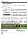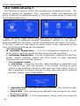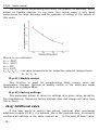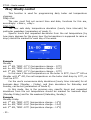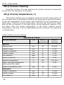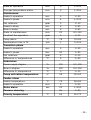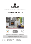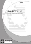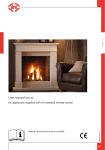
1
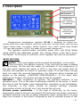
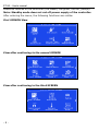
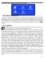
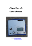
ST-95 – User's manual TECH Declaration of Conformity No. 30/2010 Hereby, we declare under sole responsibility that the ST-95 230V 50Hz thermoregulator manufactured by TECH, ul. St. Batorego 14, 34-120 Andrychów, is compliant with the Regulation by the Ministry of Economy. (Journal of Laws Dz.U. 155 Item 1089) of July 21, 2007 implementing provisions of the Low Voltage Directive (LVD) 2006/95/EC of January 16, 2007. The ST-95 controller has been tested for electromagnetic compatibility (EMC) with optimal loads applied. For compliance assessment, harmonized standards were used: PN-EN 60730-2-9:2006. Paweł Jura, Janusz Master -2- ATTENTION! High voltage! Make sure the regulator is disconnected from the mains before working on the power supply (cable connections, device installation, etc.)! All connection works must only be carried out by qualified electricians. Before activating the controller, measure the motor resetting efficiency and inspect wire insulation. -3- I. Description PLUS button MINUS button Button for entering the menu, confirming the settings Button for leaving the menu, cancelling the settings STANDBY mode Microprocessor temperature regulator ST–95 is designed for boilers for: pellets (both from clean sawdust and from wood bark, energy willow, and e.g.rape straw), grains (oats, rye, barley, wheat, charlock, corn, lupin), willow chips (length <20 mm and humidity <15%), dry seeds of e.g.sweet cherries etc.. The regulator controls water circulation pump (CH), Hot Utility Water pump (HUW), two additional pumps, two mixing valves, a fan and a worm fuel feeder. To this type of controller, room regulator can also be connected. BASIC NOTIONS Ignition – this cycle begins at the moment of activation, in the menu of the controller, the Ignition function. First, the first fuel dose is stoked on the furnace, the fan and the heater are activated. If the temperature of flue gas outlet reaches the value of 80 oC in the time not longer than 25 minutes, the regulator will switch to operation mode. If, at that time, flue gas does not reach the required temperature, the following alarm message will appear on the display: <IGNITION UNSUCCESSFUL>. In this case, after cleaning the furnace, the ignition process should be repeated. Operation – after completion of ignition, the regulator switches to the operation cycle. This is the basic functioning condition of the boiler, in which the blow-in and the feeder work automatically, according to set parameters. The controller, in this mode, should, at relevant settings, maintain temperature similar to the set one (vary around the set one). Furnace power modulation – in the case of achieving, by the boiler, temperature close to the set one (preset 3ºC below the set value) controller's operation switches into the so-called modulation state, whose task is to slow down the increase in the boiler's temperature and to combust excess of fuel -5- ST-95 – User's manual before switching to maintenance mode. Thanks to modulation, softer transition of the controller to the set temperature is possible. When the boiler reaches the set temperature the controller shall switch to the maintenance mode. Maintenance – this state is active in operation mode Mode-1 (see Chapter II.s). Maintenance will be activated automatically, if the boiler temperature reaches the set value. Maintenance mode prevents further increase in the boiler's temperature and, thanks to reduced combustion parameters, causes gradual temperature drop. The user has also the possibility to activate extinguishing mode, after exceeding set temperature. Transition phase – when the boiler's temperature, after maintenance cycle drops below set temperature by hysteresis value, in order to properly introduce the boiler into operation mode the so-called transition phase must take place, during which the controller accordingly increases combustion parameters. Transition phase is intended for flexible introduction of the boiler into operation mode. This cycle shall end when flue gas temperature, during transition phase, increases by 5oC (factory setting). Extinguishing – after activating Extinguishing function, the feeder ceases to feed fuel to the furnace and the fan runs until the moment when flue gas temperature drops below temperature of 80 oC (factory setting). After that, ash removal mechanism is activated, for cleaning the furnace. Program version is written individually for each boiler's manufacturer. Any comments concerning the program should be reported to the boiler's manufacturer. Each controller should be set individually, according to its own needs, depending on the type of fuel used for burning as well as on boiler type. The company TECH shall not be liable for any incorrect settings of the controller. II. Functions of the regulator This section describes functions of the regulator, method of changing settings, and navigation in the menu. II.a) Main page After activating the controller with a switch on the slat, language version of the controller should be selected. During normal operation of the regulator, on graphic LCD display, the main page is visible. It is divided into four basic parts: ● at the top part of the display, current temperature of the boiler, as well as set temperature, are displayed. ● in the bottom part of the display, hot water tank temperatures are accordingly displayed (provided that HUW pump has been activated - see -6- chapter II.k). ● in the right part of the display, in a graphic manner, operation of fan, feeder and pumps is displayed. Operation of each of these devices is signalled by an animation. ● in the middle part, spaces informing on active operating mode, flue gas temperature, fan power degree and type of fuel, are placed. After selecting additional pumps 1 and 2, in their place, appropriate icons, symbolizing the selected pump, will appear: - floor pump, - buffer pump, - circulation pump, - additional CH pump. The main page enables fast change of set Temperature by means of keys PLUS and MINUS Pressing the MENU button brings the user to the first SCREEN (there are four screens). In each function of a given SCREEN, it is possible to move, using buttons PLUS and MINUS . After holding the PLUS button, it is possible to proceed straightaway to the last menu function on the fourth screen (service settings). Pressing the MENU button confirms selection of the marked option and activates it. Pressing the EXIT key causes leaving active function and going to the higher level of the menu until the main page view of the controller. The standby mode button, placed on the regulator's casing, allows, if necessary, to quickly deactivate all executive devices ( press and hold). This is an additional protection of emergency disconnection of power supply for all -7- ST-95 – User's manual executive devices of the controller (the feeder, the grate, the fan, pumps). Note: Standby mode does not cut off power supply of the controller. After entering the menu, the following functions are visible: First SCREEN View View after continuing to the second SCREEN View after continuing to the third SCREEN -8- View after continuing to the fourth SCREEN II.b) Manual operation For the user's convenience, the regulator has been equipped with a Manual operation module. In this function, all executive devices (the feeder, the fan the heater, the grate, pumps and valves) are activated and deactivated independently of the others and their activation is signalled by an animated icon. In order to activate/deactivate the selected device, press the MENU button. II.c) Ignition Ignition function is used for automatic obtaining of relevant combustion conditions needed for transition to operation mode. Ignition cycle begins at the moment of activation, in the controller's menu, the ignition function. First, the first fuel dose is stoked on the furnace, then the fan and the heater are activated. The heater operates until the moment when flue gas temperature, increases by 10ºC (service setting: temperature of flue gas deactivating the heater) and is deactivated when flue gas outlet temperature reaches threshold value of 80oC (service setting: ignition temperature), the controller shall continue to operation mode. However, when flue gas, within 10 minutes (service setting: time of heater reactivation) from deactivating the heater, fails to achieve ignition temperature, the heater will be activated again and will operate until the time when flue gas outlet temperature reaches the value of at least 80 oC but not longer than 25 minutes (service setting, parameter: heater protection) from the end of stoking. If, at that time, flue gas does not reach the temperature of 80ºC (parameter: ignition temperature) the following alarm message will appear on the display: <IGNITION UNSUCCESSFUL>. In this case, after cleaning the furnace, the ignition process should be repeated. When the ignition does not succeed, deactivate the controller on the network switch and then check, whether fuel is in the furnace. If it is there, the furnace should be cleaned (emptied); if it is not there, ensure that the bunker does not lack in fuel and then, again, activate the controller and start ignition cycle. -9- ST-95 – User's manual Note: Each new ignition attempt must be preceded by cleaning the furnace. II.d) Extinguishing This function is used to extinguish the heat and clean the furnace. Before the device is disconnected from power supply, extinguishing phase must be conducted. This is supposed to fully combust fuel remainders and remove remaining ash. Note: Never deactivate the boiler with the switch on supplying slat without previously conducting extinguishing. After activating Extinguishing function, the feeder ceases to feed fuel to the furnace and the fan runs until the moment when flue gas temperature drops below 80o C (factory setting). After that, ash removal mechanism is activated, in order to clean the furnace. II.e) Fuel selection In the event when the user applies more than one type of fuel, this function allows to quickly change controller's operation parameters for another fuel type. Is possible to configure parameter settings of feeding and blow-in for maximum three types of fuel. New settings configuration for another fuel (after choosing e.g.Fuel 2) shall be made in service menu. II.f) HUW set temperature With this function, utility water temperature is set. After additional heating of water in the hot water tank up to this temperature, the regulato stops the operation of HUW pumps. The pump will be re-activated when the temperature decreases below the set value by hysteresis value (see HUW hysteresis). In house heating mode, this function is inactive. II.g) HUW hysteresis This option is used to set the hysteresis of the set temperature on the hot water tank. This is a difference between set temperature (that is, the one required on the hot water tank) – when HUW pump turns off, and pump reactivation temperature (for example: when set temperature has the value of 55OC and the hysteresis is 5OC. After reaching the set temperature, namely 55OC, HUW pump will be deactivated. The pump will be re-activated when the temperature decreases to 50OC). - 10 - II.h) HUW disinfection Thermal disinfection involves increasing temperatures to the necessary disinfection temperature of min. 60°C throughout the entire HUW disinfection. New regulations impose the obligation to adjust HUW system to periodical thermal disinfection conducted at the water temperature not lower than 70°C. Ducts, fittings and technological system of warm water preparation must comply with this condition. After selecting this function, the user proceeds to disinfection submenu: ➢ <Activated> - this option activates disinfection process that will end after the set time. During disinfection, on the main screen, the message <THERMAL DISINFECTION> will be displayed. ➢ <Set temperature> - this is the set temperature during thermal disinfection. ➢ <Operation time> - duration of disinfection (in minutes), in which set disinfection temperature will be maintained on a permanent set level. ➢ <Maximum duration> - this is the maximum total duration of disinfection, from the moment of activation, regardless of temperature. In the case when the boiler fails to reach set temperature or does not maintain, throughout operation time, the set temperature, after maximum duration, the controller will return to the basic operation mode. II.i) CH hysteresis This option is used to set the hysteresis of the set temperature. It is a difference between the temperature of entering the maintenance cycle, and the temperature of return to the operation cycle (for example: when set temperature has the value of 60ºC, and the hysteresis is 3ºC, switching to the maintenance cycle will proceed when the temperature increases to 60ºC, while the return to the operation cycle will happen will proceed when the temperature decreases to 57ºC). II.j) Room regulator To TS-95 regulator, room regulator can be connected. After its activation, the controller is set by the room regulator. The user can select the type of room regulator: ➔two-state - in cooperation with mixing valve Additional heating of the apartment up to the set temperature will cause reduction in set temperature of the valve by the value of the parameter reduction of room regulator (see: valve settings– Chapter II.item 6). Additional heating of the room regulator shall cause cyclic - 11 - ST-95 – User's manual operation of CH pump according to CH pump operation setting (activation time, pause time). - without mixing valve Additional heating of the room regulator shall cause cyclic operation of CH pump according to CH pump operation setting (activation time, pause time). ➔TECH regulator (ST-205) - in cooperation with mixing valve Any change in room temperature results in an appropriate change in the set mixing valve temperature (see: valve settings– chapters II item 8, II item 9). Additional heating of the room regulator shall cause cyclic operation of CH pump according to CH pump operation setting(activation time, pause time). - without mixing valve Additional heating of the room regulator shall cause cyclic operation of CH pump according to CH pump operation setting (activation time, pause time). In the case of connecting TECH regulator, the user has the possibility of controlling and changing the set CH and HUW temperature, as well as mixing valve temperature; any boiler controller alarms are also displayed. After activation of Room regulator option, on the main screen, in the right top corner, the message <Room reg.> will be displayed. If this text pulsates, this proves that the room is underheated (the set room regulator temperature has not been achieved). When <Room reg.> is displayed constantly, the set room temperature has been achieved. Regulator standard (twin-core cable) or ST-205 (TECH) regulator (four-core cable) NOTE: No external power source may be connected to room regulator output. - 12 - II.k) Pumps operation modes In this function, as necessary, the user activates one of four operation modes of the boiler. II.k.1) House heating By choosing this option, the regulator switches to heating the house only. CH pump starts to operate above pump activation temperature (preset at 35OC – see Chapter III.f.). Below this temperature, (minus 2 OC - CH hysteresis), the pump stops to operate. II.k.2) Boiler priority (hot water tank priority) In this mode, boiler (HUW) pump is activated, until the set temperature is reached (see Chapter II.f.), after reaching it, the pump is deactivated and CH circulation pump is activated. CH pump operates constantly until the moment when temperature. on the hot water tank drops below the set one, by HUW hysteresis value. Then CH pump is deactivated and HUW pump is activated. In this mode, operation of the fan and the feeder is limited to the temperature of 65O on the boiler, as this prevents overheating of the boiler. Note: The boiler should be equipped with return valves on the circuits of CH and HUW pumps. The valve mounted on HUW pump prevents hot water from being sucked out of the hot water tank. II.k.3) Parallel pumps In this mode, pumps' operation begins simultaneously above pump activation threshold (preset 35OC). CH pump operates continuously, while HUW pump is deactivated after reaching the temperature set at the hot water tank. II.k.4) Summer mode After activating this function, only HUW pump operates, working on additional heating of the boiler. This pump is activated above the set activation threshold (see function pump activation temperature-see Chapter II.f.) and works until achieving the set temperature of the boiler. The pump will be activated again when the temperature falls below the set CH temperature and set CH hysteresis. In the summer mode, only the set temperature is adjusted on the boiler, which additionally heats water in the hot water tank (the set boiler temperature is, at the same time, the set hot water tank temperature). - 13 - ST-95 – User's manual II.l) Additional pump 1 This function is used to control the selected type of additional pump. The types of pumps are available: floor, circulation, buffer and additional CH pump. If there is no additional pump or if we do not want to use it, select the pump deactivated option. After selecting proper pump (signalled with an asterisk), it should be possible to go to additional working parameters settings (in the case of selecting additional CH pump, it works simultaneously with basic CH pump ). To do this, press exit and select an active pump. Then, depending on the type, the following settings will be available: ➢for floor pump minimum temperature – it is the temperature measured on CH boiler, whose reaching causes the floor pump to start operating, maximum temperature - it is the temperature measured on the floor sensor, whose reaching causes the floor pump to stop operating (measurement from the floor sensor); ➢ for circulation pump start/stop – using this function, daily activation or standstill cycle of a pump is set, with the accuracy of 30 minutes. Marking of pump activity in the selected interval is made with the PLUS button. There is also a possibility of copying settings to other time intervals by pressing the EXIT button (Then PLUS/MINUS). operation time – the required pump operation time should be set, when it is active, pause time – the required pump standstill time should be set, when the pump is active, pump threshold – it is the temperature, above which the pump will - 14 - not be activated; this threshold prevents unnecessary operation of pump, when water in the installation is sufficiently hot; ➢ for buffer pump minimum temperature – it is the temperature measured on boiler, whose reaching causes buffer pump to start operating, maximum temperature - it is the temperature measured on buffer tank sensor, whose reaching causes buffer pump to deactivated. the CH the be In the case of selecting additional CH pump, its activation and operation time will be indentical with basic CH pump (parallel operation). II.m) Additional pump 2 Thanks to this options, the user has the possibility to connect the second additional pump to the regulator. To do that, type of additional pump 2 and its settings should be selected, just as for additional pump 1. II.n) Antifreeze (anti-freezing) of pumps Antifreeze function activates all active pumps at the time of reduction in CH circulating water temperature below pump activation temperature (antifreeze activation temperature) which prevents freezing of water in the system. After activation of this <deactivate> function, the user has the possibility to determine pump activation temperature (preset is 6o C). II.o) Anti-stop of pumps Controller is equipped with a system preventing too long lack of operation of pump engines, the so-called "anti-stop". After activating this (deactivate) function, once a week, pumps will be activated, in accordance with set parameters (time of activation and day of the week, as well as operation time). Additionally, time is saved every hour in non-volatile memory EEPROM, thanks to which, after possible break in supply, time measurement is continued. II.p) Valve This option is used to set operation of the mixing valve. After activating this (deactivate) function, for the valve to operate correctly and in accordance with the user's expectation, several parameters should be set. - 15 - ST-95 – User's manual NOTE: connection of 4-way valve should be made in the way ensuring that on boiler – valve section, gravitational circulation of the boiler is possible (preserved minimum nominal diameter DN 50 and drops), while the mixing valve may be installed at least 30cm over warm water outlet from the boiler. II.p.1) Set temperature [oC] By means of this setting, temperature (the set temperature) value should be introduced, which will be maintained behind the valve. II.p.2) Opening time [sec] In this function, opening time is set (in seconds), in other words, how long it takes the valve to open to the value of 100%. This time should be selected according to the owned valve servomotor (stated on the rating plate). II.p.3) Minimum opening [%] In this function, the minimum valve opening value is set. Below this value, the mixing valve will not close any further. II.p.4) Unit stroke [%] In this function, per cent unit stroke of valve opening is set, namely which maximum opening or closing percent may each time be performed by the mixing valve (maximum valve movement in one measurement cycle). II.p.5) Temperature control [sec] This parameter determines sampling (control) frequency of the water temperature behind the valve for CH or HUW installation (in seconds). If the sensor indicates a change in temperature (deviation from the set value), then the electric valve will open or close by set stroke, in order to return to the set temperature. II.p.6) Reduction of room regulator [o C] This function is active only in cooperation of the controller with the twostate room (standard) regulator. When the room regulator reaches the set temperature in the appartment, (reports additional heating), the mixing valve shall close, so that the temperature behind the valve decreased by the temperature of <reduction of room regulator>. II.p.7) Valve type With the use of this option, the user selects the type of valve used: CH or floor. In the case of uncontrolled overheating of the boiler (alarm), in the case of CH valve, its full opening will take place, whereas, in the case of floor - 16 - valve, it will be maximally closed. NOTE: When using valve module to control floor heating, external thermostat protecting floor installation (disconnecting power supply of mixer pump after exceeding the maximum temperature – 55oC) should be additionally installed. II.p.8) Difference in room temperatures This setting determines a change in temperature of room regulator at which change in the set valve temperature will take place. II.p.9) Change in set valve temperature This setting determines by how much degrees the temperature will increase or decrease when changing room regulator temperature (Difference in room temperatures). Example: setting: Difference in room temperatures 0.5ºC setting: Change in set valve temperature 1ºC setting: Valve set temperature 40ºC setting: Set room regulator temperature 23ºC Case 1. If the room temperature increases up to 24ºC (by 1ºC), the mixing valve will close to the set 38ºC (by 2ºC). Case 2. If the room temperature drops to 21ºC (by 2ºC), the mixing valve opens to the set 44ºC (by 4ºC). II.p.10) Weather control By means of this parameter, it is possible to adjust the set valve temperature for relevant values of external temperatures. On the basis of agreed points, values for intermediate points are calculated. TEMP. FOR -20 TEMP. FOR -10 TEMP. FOR 0 TEMP. FOR 10 Heating curve – it is a curve, according to which the set controller temperature is determined, on the basis of external temperature. In our controller, this curve, is constructed on the basis of four points of set temperatures for respective values of external temperatures. Set temperatures must be determined for external temperatures - 20ºC, - 10ºC, 0ºC and 10ºC. - 17 - ST-95 – User's manual The more points constructing the curve, the greater its accuracy, which allows its flexible shaping. In our case, four points seem a very good compromise for large accuracy and for easiness of setting of the course of this curve. Where, in our controller: XA = -20ºC, XB = -10ºC, XC = 0ºC, XD = 10ºC, YA, YB, YC, YD – set valve temperatures for respective external temperatures: XA, XB, XC, XD II.p.11) Weekly control This function is used for programming daily mixing valve set temperature changes. Settings of weekly control of the valve are made identically as in chapter II.u. II.p.12) Factory settings This parameter allows to return to settings of a given valve, saved by the manufacturer. Restoring factory settings does not change set valve type (CH or floor). II.q) Additional valve If the user wants to control two valves, (optional, after purchasing additional module ST-61), it is advised, like in the previous case, to correctly configure all settings in the same manner as in the case of basic valve. - 18 - Additionally, however, registration should be done by entering, Registration function, the number on casing of the additional module. in II.r) Return protection Using this function, the user activates or deactivates protection return activity. It is a protection against too low temperature of water returning to the boiler, preventing low-temperature corrosion. Note: Care should be taken of proper contact between the return sensor and the pipe! A sensor mounted on a return pipe should be thoroughly insulated. After activating this function, the following return protection parameters should be set: MIN. TEMP. OF RETURN - minimum temperature of short circulation of the boiler installation, which must be maintained before opening the valve. CLOSING RETURN VALVE – it is a minimum possible valve opening value expressed as percent. For instance, if the set value is 20%, this means that the mixing valve may close maximally for 80%. II.s) Burning modes This option enables the selection of operational mode of the boiler between burning with automatic feeder and manual burning without feeder. In the case of selecting manual burning, unnecessary functions in the menu are invisible. II.t) Operation mode This option enables selection of operational mode of the boiler after reaching the set temperature. It is possible to set one of two modes: - operation-maintenance T1 – is a standard operation mode, when the controller switches to maintenance cycle, - Operation - extinguishing T2 – in this mode, the controller, after reaching the set temperature (and after set time in the service menu) may start the process of extinguishing of the boiler (in the same way as after activating extinguishing function in the menu). When the temperature drops below the set CH temperature by hysteresis value, ignition process begins anew (from stoking). - 19 - ST-95 – User's manual II.u) Weekly control This function is used for programming daily boiler set temperature changes. Step one: The user must first set current time and date, functions for this are, accordingly: <time>, <day>. Step two: The user sets daily temperature deviation (hourly time intervals) for particular weekdays (parameters of mode 1). Specific hours and requested deviations from the set temperature (by how many degrees for the given hour the temperature is supposed to raise or drop) should be marked for each day of the week. Example Monday set: 300 AM, TEMP -100 C (temperature change – 100C) set: 400 AM, TEMP -100 C (temperature change – 100C) set: 500 AM, TEMP -100 C (temperature change – 100C) In this case if the set temperature on the boiler is 50 0C, from 300 AM on Monday until 600 AM, the set temperature on the boiler shall drop by 10 0C, so it will be 400C. For the user's convenience daily deviations (hourly time intervals) for all business days (Monday - Friday), and then deviations for Saturday and Sunday, can be set (parameters of mode 2). In this mode, like in the previous one, specific hours and requested deviations from the set temperature should be marked for business days (Monday-Friday) and for the weekend (Saturday, Sunday). Example Monday-Friday set: 300 AM, TEMP -100C (temperature change – 100C) set: 400 AM, TEMP -100C (temperature change – 100C) set: 500 AM, TEMP -100C (temperature change – 100C) - 20 - Saturday-Sunday set: 4 00 PM, temperature 50C (temperature change + 50C) set: 500 PM, temperature 50C (temperature change + 50C) set: 600 PM, temperature 50C (temperature change + 50C) In this case, if the set temperature on the boiler is 50 0C, from 300 AM until 600 AM, every day of the week from Monday to Friday, the set temperature in the boiler shall drop by 100C, so it will be 400C. On the other hand, during the weekend (Saturday, Sunday) from 400 PM to 700 PM the set temperature on the boiler will increase by 5 0C, so it will be 550C. Step three (Mode): The User activates one of the two previously set modes (Mode1, Mode2), or completely deactivates weekly control option. After activating one of the modes on the main page of the controller, letter "T1", or "T2" will appear (digit informs on active mode), informing on weekly regulator operation. II.v) Factory settings The regulator is pre-configured for operation. However, it should be adjusted for own needs. Return to the factory settings is possible at any moment. By activating factory settings options, all own adjustments of the boiler (saved in user's menu) are lost, substituted by settings saved by the manufacturer of the boiler. From that moment, own boiler parameters can be set again. Note: Return to factory settings does not delete changes in service settings. Factory service settings are included in the table on page 28 of this instruction. II.w) Contrast This function is used for setting brightness of graphic display by means of buttons plus and minus. - 21 - ST-95 – User's manual III. Service settings To start service settings enter the code: 5162. III.a) Ignition In this submenu, the installer sets all working parameters of the boiler during ignition process. III.a.1) Stoking time [sec] This function is used to set the feeder's operation time during feeding the first fuel dose on furnace. After the end of stoking, the blow-in and the heater are activated. III.a.2) Feeder delay [min] This option is used for setting blow-in operation time, the feeder is activated. Thanks to feeder delay function, first, the fan is activated and after the set time, the feeder is activated. It is the blockade of feeder's operation for a given time. III.a.3) Feeder's operation [sec] This option is used for setting the fuel feeder operation time during ignition process. Operation time during ignition should be set depending on the kind of fuel used (its calorific value) and type of the boiler. III.a.4) Feeder's pause [sec] Feeder's pause function is used for setting fuel feeding pause time during ignition process; The pause should be adjusted to the type of fuel combusted in the boiler. Wrong selection of the operation time as well as the pause may result in unsuccessful ignition. Selection of proper working times and feeder's pause allows optimal transition from ignition to operation mode. III.a.5) Fan rotations [gear] This option allows to select proper blow-in power during ignition. Regulation range is within 1 and 10, (it can be assumed that these are the fan's gears). The higher the gear, the faster the fan is operating. III.a.6) Heater protection [min] This parameter is set in order to prevent destruction of incandescent spiral and to set maximum time of ignition. Time of heater protection is counted from the moment of stoking completion. If flue gas temperature, at - 22 - that time, does not increase to ignition temperature (preset 80o C) the following alarm message will appear on the display: <IGNITION UNSUCCESSFUL>. In this case, after cleaning the furnace, ignition process should be repeated. III.a.7) Ignition temperature [0C] This function is used to set the threshold flue gas outlet temperature, whose reaching (in a given period) causes the controller to switch to operation mode. III.a.8) Flue gas temperature deactivating. the heater [ 0C] After the end of stoking, temperature measurement is performed, and then, the first activation of the heater takes place. The heater works until the time when flue gas temperature increases by value set in this function. After deactivating the heater, the controller remains in <IGNITION> mode until reaching flue gas outlet temperature according to parameter: Ignition temperature. III.a.9) Time of heater re-activation [min] Using this function, time between first deactivation of the heater, and the next activation is set. Second heater activation will follow the set heater re-activation time, only when the controller does not start operation mode earlier. In the event when the heater activates again, it will operate until the moment when flue gas reaches ignition temperature or until heater protection. III.b) Operation In this submenu, the installer sets all working parameters of the boiler during operation cycle. III.b.1) Feeder's operation [sec] This option is used for setting the fuel feeder operation time during operation cycle of the controller. Operation time should be set depending on the kind of fuel used (its calorific value), type and power of the boiler. III.b.2) Feeder's pause [sec] Feeder's pause function is used for setting fuel feeding pause time of operation cycle; The pause should be adjusted to the type of fuel combusted in the boiler. Wrong selection of the operation time as well as the pause may result in faulty functioning of the boiler, i.e. fuel may not be burned or the boiler may not reach the set temperature. Selection of proper working times - 23 - ST-95 – User's manual and feeder's pause allows correct operation of the boiler. III.b.3) Fan rotations [gear] This option allows to select proper blow-in power in operation mode. Regulation range is within 1 and 10. The higher the gear, the faster the fan is operating. III.b.4) Grate at operation [min] This parameter determines the frequency of regular furnace cleaning. Installer sets the interval between activation of furnace cleaning function. Grate interval should be selected depending on the type of combusted fuel and forms of created ash. III.b.5) Flue gas temperature alarm [min] This setting is active in operation mode, when the boiler temperature falls below ignition threshold temperature (and CH hysteresis). In such a case, when, in the set time, (flue gas temperature alarm mode), flue gas temperature does not increase, alarm message will appear on the display. ________________________________________________________________________________________________________________________________________________ Note: The parameters feeder's operation, feeder's pause, fan rotations and setting automatic furnace cleaning operation (Grate at operation) are very important parameters. Their improper setting may result in improper combustion in the boiler. For some fuels, also regulation of air stream separation for the furnace grate operation or directly for combustion zone is necessary (see boiler manufacturer's guidelines). ________________________________________________________________________________________________________________________________________________ III.c) Maintenance In this submenu, the installer sets parameters of the boiler operation after switching to maintenance cycle (after reaching the set temperature of the boiler). III.c.1) Feeder's operation [sec] This option is used for setting fuel feeder operation time during maintenance cycle. III.c.2) Feeder's pause [min] Feeder's pause is used for setting fuel feeding pause time of maintenance cycle. Wrong selection of the operation time as well as the - 24 - pause may result in further increase in temperature, unintentional extinguishing of the boiler, or conditions in which it may come to ignition of the fuel in the fuel container. III.c.3) Fan rotations [gear] This option allows to select proper blow-in power in maintenance. Regulation range is within 1 and 10. The higher the gear, the faster the fan is operating. III.c.4) Feeder delay [sec] This option is used for setting blow-in operation time, the feeder is activated. Thanks to feeder delay function, first, the fan is activated and after the set time, the feeder is activated. This function aims at initial heating of fuel before covering a new portion of fuel. III.c.5) Fan delay [sec] After finishing feeder's operation, the fan will still run for the time set in this function. This option allows to delay deactivation of the fan in order to improve the ignition of covered portion of fuel. III.c.6) Grate in maintenance [min] This parameter determines the frequency of regular furnace cleaning during maintenance cycle. The installer sets the interval between activation of furnace cleaning function. III.c.7) Constant fan operation [gear] In maintenance, it is possible to set permanent blow-in speed at any gear. In the case of setting the "0" value, the fan shall be activated simultaneously with feeder's operation (values set in the parameters: feeder delay and blow-in delay). III.c.8) Pump alarm [oC] In this function, alarm activation of CH and HUW pumps is set. In case of significant increase in temperature on the boiler (to alarm temperature – preset 85o C) CH and HUW pumps will be activated. (if they do not operate at that time) in order to distribute, throughout the installation, excess of hot water in the boiler. When temperature drops below the alarm level, the controller will return to normal operation. If House heating operation mode is activated, HUW pump is inactive and, at the alarm, it will not be activated. - 25 - ST-95 – User's manual III.c.9) Maintenance time in T2 [min] This setting shall be active only in the case of selecting operation mode T2 (extinguishing - ignition in maintenance). The user sets time between achieving set temperature (switching to maintenance) and the commencement of extinguishing. In the case when, in set time, temperature falls below the set one, the boiler will not switch to extinguishing phase. III.d) Transition phase In this submenu, the installer sets all operation parameters of the boiler during transition phase (after maintenance). III.d.1) Feeder's operation [sec] This option is used for setting operation time of the fuel feeder during transition phase. III.d.2) Feeder's pause [sec] Feeder's pause function is used to set fuel feeding time pause during transition phase. III.d.3) Fan rotations [gear] This option allows to select proper blow-in power in transition phase. Regulation range is within 1 to 10. The higher the gear, the faster the fan is operating. III.d.4) Difference in temperatures [oC] This setting determines transition phase duration. When the temperature of the boiler drops below the set value and the set hysteresis, controller records flue gas temperature. Transition phase will last until flue gas temperature does not rise by the amount of the parameter difference in temperatures (preset is 50C). III.e) Modulation In the case of reaching, by the boiler, temperature close the set one (preset 3ºC below the set value), operation of the controller switches into the so-called. modulation state, whose task is to slow down the growth rate of the boiler's temperature. - 26 - III.e.1) Power supply degree [%] By means of this setting , it is possble to change percentage of quantity of fuel delivered to the furnace after the controller switches to modulation state. III.e.2) Blow-in degree [%] By means of this setting , it is possble to change percentage of blow-in fan power after the controller switches to modulation state. III.e.3) Difference in temperature [oC] By means of this parameter, it can be set, by how many degrees Celsius below the set value, the controller shall switch to modulation phase. III.f) Pump activation temperature [oC] This option is used to set pump activation temperature of CH HUW pump (this is the temperature measured on the boiler). Below this temperature, both pumps do not work and after reaching activation temperature, they are active and operate depending on the operation mode. III.g) Feeder alarm [oC] In this submenu, covering parameters after the feeder alarm are set. In order to avoid fire hazard, fuel from the feeder will be transported to furnace. III.g.1) Feeder temperature [oC] This parameter determines temperature of the feeder's sensor, whose reaching causes feeder alarm to occur (the furnace to be covered). III.g.2) Feeder's operation [min] Using this parameter, fuel feeding time after the feeder alarm is determined. III.h) Grate alarm [sek] This function is used to set the time after which the alarm informing about grate failure will occur. In the case of blocking of the poker and, as a result the lack of signal from hallotron sensor, after set time, the <GRATE ERROR> message will appear on the display, along with acoustic signal. - 27 - ST-95 – User's manual III.i) Furnace cleaning Using this function, the user declares the number of poker's movements during one-time operation of the grate. III.j) Priority temperature [oC] This function applies only to operation mode of hot water tank priority. If the hot water tank is insufficiently heated, this temperature performs function of the set temperature of the boiler until achieving the set temperature of HUW pump. Thanks to priority temperature, the boile will heat the hot water tank as fast as possible. In the case when, during additional heating of the hot water tank, the actual temperature in the boiler reaches priority temperature, the blow-in will be deactivated and the controller will operate as in maintenance. Table of factory service settings SERVICE SETTINGS Service function Unit Factory parameters Scope of settings Stoking time sec. 15 6÷100 Feeder's delay min. 4 0÷20 Feeder's operation sec. 3 1÷150 Feeder's pause sec. 40 1÷50 Fan rotations gear 8 1÷10 Heater protection min. 25 1÷30 Ignition Ignition temperature o C 80 20÷300 Temp. Flue gas temperature deactivating the heater o C 10 1÷50 min 10 1÷20 Feeder's operation sec. 2 1÷250 Feeder's pause sec. 28 1÷250 Fan rotations gear 7 1÷10 Heater re-activation time Operation - 28 - Grate at operation min. 5 1÷120 Flue gas temperature alarm min. 5 1÷250 Feeder's operation sec. 2 1÷20 Feeder's pause min. 4 1÷120 Fan rotations gear 3 1÷10 Feeder's delay sec. 6 1÷60 Blow-in delay sec. 6 1÷60 Grate in maintenance min. 20 20÷120 Constant fan operation gear 0 1÷10 C 78 75÷80 min 1 0÷120 Feeder's operation sec. 5 1÷50 Feeder's pause sec. 40 1÷50 Fan rotations gear 5 1÷10 C 5 1÷50 Power supply degree % 100 10÷100 Blow-in degree % 100 10÷100 Difference in temperature o C 3 1÷10 Pump activation temperature o C 35 30÷60 o C 75 55÷80 min. 3 1÷20 sec 20 1÷250 8x 1÷60 65 50÷70 Maintenance Pump alarm Maintanance time in T2 o Transition phase Difference in temperatures o Modulation Feeder alarm Feeder temperature Feeder's operation Grate alarm Furnace cleaning Priority temperature o C - 29 - ST-95 – User's manual IV. Protections To ensure maximally safe and unfailing operation, the regulator has been equipped with a number of protections. In the event of an alarm, a sound signal is activated and a relevant message is shown on the display. To make the controller return to operation, press the MENU button. In the event of an alarm, CH temperature too high, wait a moment for this temperature to decrease below the alarm level. IV.a) Waste gas temperature alarm This protection is activated only in operation mode (If the boiler temperature is lower than the set temperature). If the boiler temperature does not rise within the time specified by the user, the alarm is activated, the feeder and the blow-in are deactivated and a sound signal is activated. On the display, the following message appears: "Temperature does not rise" . IV.b) Thermal protection of the boiler It is an additional bimetallic mini-sensor (located at the boiler temperature sensor – or on power supply pipe, as close as possible to the boiler), disconnecting the fan and the feeder in the event of exceeding the alarm temperature – 85O C. Its activation prevents boiling of water in the installation, in the case of overheating of the boiler or damage of the controller. After actuation of this protection, when the temperature goes down to a safe values, the sensor will be unlocked automatically and the alarm will be deactivated In the case of damage or overheating for this sensor, the burner, the fan and the feeder will be disconnected. IV.c) Automatic sensor control In the event of damage of the CH or the HUW temperature sensor, the worm or the fuel container, a sound alarm is activated additionally signalling the defect on the relevant display, e.g.: "CH sensor damaged ". The feeder and the blow-in are then deactivated. The pump is turned on regardless of the current temperature. In the case of damage of CH sensor or the feeder, the alarm will be active until the sensor is replaced with a new one. If the HUW sensor is damaged, press the MENU button, which will deactivate the alarm, and the controller will return to the one pump (CH) operation mode. To enable the boiler, to work in all modes, the sensor must be replaced with a new one. - 30 - IV.d) Protection of boiling of water in the boiler This protection applies only to the operation mode of hot water tank priority, in the event when the tank is insufficiently heated. When the hot water tank temperature is set at e.g.. 55 O C and the actual temperature in the boiler rises up to 65O C (this is the so-called. priority temperature), then the controller will deactivate the feeder and the fan. If the temperature in the boiler still rises up to 78 O C, CH pump will be activated. If the temperature is still rising, at the temperature of 85O C the alarm will be activated . Most often, such a condition may appear when the hot water tank is damaged, the sensor is improperly fitted, the pump is damaged. However, when the temperature drops, then, at the threshold of 63 O C, the controller will activate the feeder and the blow-in and will operate in the operation mode until reaching the temperature of 65O C. IV.e) Temperature protection The regulator is equipped with additional protection in the event of damage of the bimetallic sensor. After exceeding the temperature of 85ºC, the alarm is activated - signalling the following on the display: "Temperature too high". Despite the damage to the bimetallic sensor, the controller receives information about the current temperature in the boiler from the electronic sensor. In the case of exceeding the alarm temperature, the fan is disconnected and at the same time, both pumps begin to operate, in order to distribute hot water throughout the house installation. IV.f) Fuse The regulator is equipped with tubular fuse insert WT 6.3A, protecting the network. Using a fuse with a higher value may cause damage to the controller. V. Maintenance In ST-95 controller, before the heating season and throughout its duration, technical condition of wires should be checked. Also fastening of the controller should be checked, it should be cleaned from dust and other dirt. It is also advised to measure earthing effectiveness of the engines (CH pump, HUW pump, the blow-in and the feeder). - 31 - ST-95 – User's manual TECHNICAL DATA No. Specification Unit 1 Power supply V 230V/50Hz +/-10% 2 Power consumption W 16 3 Ambient temperature O 10÷50 4 Feeder output load A 2 5 Output load of each pump A 0,5 6 Blow-in output load A 0,6 7 Range of temperature measurement O 8 Accuracy of measurement O 9 Range of temperature settings O 10 Sensor temperature strength of the sensor 11 Fuse insert VI. C C 0÷85 C 1 C 30÷80 O C -25÷90 A 2x6,3 Installation Installation should be performed by a person with relevant authorizations! At that time, the device cannot be at live voltage (make sure that the plug is disconnected from the power network)! Note: ST-95 CONTROLLER MUST BE USED , FOR INSTALLATION OF THE BOILER SO THAT THERE WAS NO ACCESS TO CABLE INSTALLATION SLATS. NOTE: incorrect connection of wires may cause damage to the regulator! The regulator cannot operate in a closed central heating system. Safety valves, pressure valves and a levelling tank protecting the boiler against boiling of the water in the central heating system must be installed. - 32 - VI.a) Sample hydraulic schemes NOTE: The following schemes do not constitute the central heating system design - they only illustrate the possibility to use controller's functions. 1.a) 1.b) 2) - 33 - ST-95 – User's manual 3) 4) - 34 - Table of Contents I. Description.................................................................................................5 II. Functions of the regulator............................................................................6 II.a) Main page............................................................................................6 II.b) Manual operation..................................................................................9 II.c) Ignition...............................................................................................9 II.d) Extinguishing.....................................................................................10 II.e) Fuel selection.....................................................................................10 II.f) HUW set temperature...........................................................................10 II.g) HUW hysteresis..................................................................................10 II.h) HUW disinfection................................................................................11 II.i) CH hysteresis......................................................................................11 II.j) Room regulator...................................................................................11 II.k) Pumps operation modes.......................................................................13 II.l) Additional pump 1................................................................................14 II.m) Additional pump 2..............................................................................15 II.n) Antifreeze (anti-freezing) of pumps.......................................................15 II.o) Anti-stop of pumps.............................................................................15 II.p) Valve................................................................................................15 II.q) Additional valve..................................................................................18 II.r) Return protection................................................................................19 II.s) Burning modes...................................................................................19 II.t) Operation mode..................................................................................19 II.u) Weekly control...................................................................................20 II.v) Factory settings..................................................................................21 II.w) Contrast............................................................................................21 III. Service settings.......................................................................................22 IV. Protections..............................................................................................30 IV.a) Waste gas temperature alarm..............................................................30 IV.b) Thermal protection of the boiler...........................................................30 IV.c) Automatic sensor control.....................................................................30 IV.d) Protection of boiling of water in the boiler.............................................31 IV.e) Temperature protection......................................................................31 IV.f) Fuse..................................................................................................31 V. Maintenance.............................................................................................31 VI. Installation..............................................................................................32 VI.a) Sample hydraulic schemes..................................................................33 - 35 -