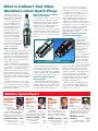
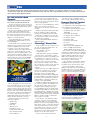
1
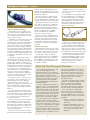
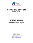
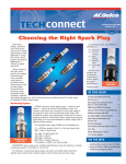
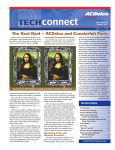
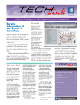
October/November 2004
Volume 11, No.6
Fuel Injector Cleaning
In time, fuel injector(s) may become
restricted, due to buildup in the injector
passages. Restrictions cause an injector
to run lean. Driveability symptoms include
difficult starts, rough operation and possible misfire. The MIL may illuminate.
Injector cleaning has three
phases: dealing
with fretting
corrosion, injector balance testing, and cleaning. Here are
some of the
reasons behind
Typical Multec II Injector
the procedures.
ting is that it can cause symptoms that
mimic a restricted injector. The worst
case is a total loss of continuity in the
connection that results in injector circuit
fault or misfire codes being set. If the
oxides create a high resistance circuit,
insufficient current will be available to
properly open the injector, resulting in
unstable fuel delivery.
Applying lubricant
continued on page 3
IN THIS ISSUE
Fretting Corrosion
Fretting is a microscopic rubbing motion
between the terminal pin on the injector
and the terminal in the wiring harness,
usually caused by injector vibration,
engine vibration and electrical harness
movement. It is invisible to the naked eye.
Oxidized debris (corrosion), the result
of fretting, can build up in the injector terminals, resulting in high resistance or
loss of continuity. A fretted connection is
unstable, and may vary between good,
high resistance and open, depending on
the amount of oxide build-up.
The reason to be concerned about fret-
conditions still exist for fretting to occur,
it will eventually come back.
To ensure that fretting is not an issue,
apply dielectric grease to both cavities
of each injector connector. This provides
a lubricant for the terminals as well as
an oxygen barrier to guard against oxide
formation.
The GM part number for dielectric
grease in the U.S. is 12377900. In
Canada, the GM part number is
10953529.
To apply the lubricant, gather a small
amount (about the size of a BB) on the
end of your finger. Press it into the end
of the disconnected female connector,
making sure to cover both cavities.
Reconnecting the harness connection
onto the injector will wipe the lubricant
onto the male terminal pins.
Step 1. Stable connection
Step 2. Progression of fretting corrosion
Step 3. Formation of oxide layer
Step 4. Unstable connection
Disconnecting and reconnecting the
injector connector will temporarily scrape
the oxides off, creating a good connection. This explains why replacing a suspected faulty injector with a new injector
appears to repair the condition. But, if the
1
Fuel Injector Cleaning . . . . . . . . . . . . . . . . . .1
Duramax 6600 Diesel Engine Seminar . . . .2
Top Tier Detergent Gasoline . . . . . . . . . . . .3
Making an Impact with Customers
On Hold . . . . . . . . . . . . . . . . . . . . . . . . . . . .4
Get a Deal on a Dell . . . . . . . . . . . . . . . . . . .4
Buying a Business Grade Computer . . . . .4
The Mastertech CAN . . . . . . . . . . . . . . . . . .5
Iridium Spark Plug Questions . . . . . . . . . . .6
Sports Report . . . . . . . . . . . . . . . . . . . . . . . . .6
Tech Tips . . . . . . . . . . . . . . . . . . . . . . . . . . . . .7
Getting Ready for the Cold . . . . . . . . . . . . . .8
Ceramic Brake Pad Friction Material
Data Online . . . . . . . . . . . . . . . . . . . . . . . .8
acdelcotechconnect.com
New Duramax 6600 Diesel Engine
Seminar Available
A new ACDelco seminar on the
Duramax 6600 diesel engine is now
being conducted at Warehouse
Distributors (WD).
Duramax 6600 Diesel Engine
(SS-FD-1.01) covers the unique features, such as the common rail fuel
system, of the two Duramax 6.6-liter
diesel engines, Regular Production
Option (RPO) LB7 introduced in 2001
and RPO LLY introduced in 2004. The
four-hour seminar has been designed for
experienced diesel engine technicians.
ACDelco TechConnect is published
bi-monthly for retail technicians to
provide timely service information,
increase knowledge and improve
the performance of the service
center.
Publisher & Editor:
Greg Baker
ACDelco
E-mail /
[email protected]
RPO LB7 Engine Features
The RPO LB7 Duramax 6600 diesel
engine was produced between the 2001
and early part of 2004 model years. The
LB7 diesel engine produces 300 horsepower at 3100 rpm and 520 lb.-ft. of
torque at 1800 rpm and features a
Robert Bosch direct injection fuel system
that can produce fuel pressures up to a
maximum of 23,000 psi.
The first part of the seminar reviews
the following major systems of the
Duramax 6600 diesel engine, RPO LB7:
• Mechanical
• Lubrication
• Cooling
• Air induction and turbocharger
• Glow plug
• Crankcase ventilation
• Fuel
• Engine management
Duramax features that are highlighted
include the direct injection “common rail
fuel system,” which provides an exact
air/fuel ratio for every combustion stroke
for maximum power, along with the efficiency of the four overhead valves per
cylinder design and the fuel pulse shaping strategy.
The common rail fuel system consists
of a high pressure pump assembly, a fuel
filter assembly, two common fuel rails
(each rail supplies fuel to four injectors,
hence the name common rail), a high
pressure junction block (with a pressure
limiting valve and a fuel pressure sensor)
and a Fuel Injection Control Module (FICM).
The common rail fuel system has several advantages over more traditional fuel
systems, such as fuel injection pressure
that is independent of engine speed and
load as well as lower noise and less
emissions due to pilot fuel injection pressure. Pilot injection uses a small amount
of fuel that is injected at engine speeds
below 2,500 rpm, followed immediately
by normal injection.
RPO LLY Engine Features
The second part of the seminar covers
the Duramax 6600 diesel engine, RPO
LLY, which began production in January
2004. The LLY diesel engine produces
more power than the
RPO LB7 engine and is
also used in medium-duty truck applications. It generates 310 horsepower at
3100 rpm and 590 lb.-ft. of torque at
1600 rpm. In addition to more power, this
engine has a nearly 90% reduction in
exhaust emissions for Hydrocarbons,
Oxides of Nitrogen and particulates.
The important changes made to the
Duramax 6600 diesel engine, RPO LLY,
that are covered in the seminar include:
• Variable nozzle turbocharger
• Digital Exhaust Gas Recirculation
(EGR)
• Fast heating glow plugs
• Closed crankcase ventilating system
• Revised fuel system
Changes to the turbocharger, for example, contribute to the power gain of the LLY
version of the Duramax 6600 diesel engine.
An efficient turbocharger spins up fast to
produce boost pressure early, but does not
create excessive exhaust backpressure
at the engine’s upper operating range.
The variable nozzle turbocharger features a group of nine adjustable vanes in
place of the wastegate used in the LB7
engine. The vanes are opened to minimize flow at the turbine and exhaust
backpressure at low engine speeds. To
increase turbine speed, the vanes are
closed, increasing the velocity of the
exhaust gases.
The variable nozzle turbocharger allows
for a quicker-acting turbocharger at low
power levers while significantly reducing
turbine-induced exhaust backpressure at
high power and rpm levels.
To learn more about the features of the
Duramax 6600 diesel engine, contact
your WD to find out when the Duramax
6600 Diesel Engine seminar will be held
in your area.
For a more in-depth study of the
Duramax 6600 diesel engine, enroll in the
two-day Duramax 6600 training course
FCD-11. You can review the current
ACDelco training schedule and enroll in
courses online by clicking on the Training
link at acdelcotechconnect.com.
2
Technical Editors:
Mark Spencer
E-mail /
[email protected]
Jim Horner
E-mail /
[email protected]
Desktop Publishing:
Greg Szpaichler, MediaWurks
E-mail /
[email protected]
Write to: *
ACDelco TechConnect
P.O. Box 500
Troy, MI 48007-0500
:
On the Web:
acdelcotechconnect.com
ACDelco service tips are intended for
use by professional technicians, not a
“do-it-yourselfer.” They are written to
inform those technicians of conditions that may occur on some vehicles, or to provide information that
could assist in the proper service of a
vehicle. Properly trained technicians
have the equipment, tools, safety
instructions and know-how to do a
job properly and safely. If a condition
is described, it cannot be assumed
that the information applies to all
vehicles or that all vehicles will have
that condition.
All materials and programs described
in this magazine are subject to
change. Submission of materials
implies the right to edit and publish.
Inclusion in the publication is not
necessarily an endorsement of the
individual or the company.
TechConnect is published for
ACDelco by Sandy Corporation,
Troy, MI.
©2004 ACDelco. All rights reserved.
Fuel Injector Cleaning
— from page 1
Properly applied lubricant
Injector Balance Testing
An important reason for balance testing is that it quickly and graphically indicates the flow of each injector, and permits comparing the performance of each
injector with the others.
The balance test determines the condition of the injectors on the vehicle by
comparing injector pressure drops. An initial fuel system pressure is achieved for
each injector. Each injector is individually
pulsed with the same number of pulses
for the same time duration. By using two
constants (starting fuel system pressure
and pulse width/duration), the differences
in injector can be compared based on the
fuel pressure dropped by each injector as
it is pulsed.
The balance test procedure calls for
attaching a pressure gauge to the fuel
rail. The gauge must be in good operating
condition and capable of reading in kilopascals (kPa). The reason for reading kPa
instead of psi is that kPa is a much smaller measuring increment, which permits
a much more precise measurement. It
takes a difference of only 20 kPa between
injectors to cause a misfire. 20 kPa is
equivalent to 3 psi. Most psi gauges do
not have enough resolution to accurately
represent such small changes.
To perform the test, connect the pressure gauge to the fuel rail pressure connection. Purge air from the gauge by
opening the valve on the side of the
gauge and cycling the fuel pump (this can
be accomplished by turning the ignition
switch on, then off for 30 seconds, then
back on).
Fuel system pressure must be at the
desired specification in the service manual. Fuel pressure must not leak down at a
rate of more than 5 kPa in 30 seconds. If
a concern exists, follow diagnostics in
the service manual.
Next, connect the scan tool and select
Injector Balance Test. Select injector 1.
The fuel system will prime. Record the
Initial Pressure reading immediately after
the fuel pump shuts off. It is normal for
the fuel system pressure to rise due to
warm fuels vaporizing.
Pulse the first injector and record the
Pressure After Pulse reading immediately
after the injector stops pulsing. Select
and test each remaining injector, recording both the Initial Pressure and Pressure
After Pulse readings.
Once the testing is completed, subtract the Pressure After Pulse reading
from the Initial Pressure reading for each
cylinder to determine the pressure drop.
After determining the amount of pressure drop for each injector, compare the
results. If the difference between the
highest (richest) and lowest (leanest)
injector is less than 20 kPa, the injectors
are all flowing within an acceptable
range. If the difference is 20 kPa or
more, proceed with cleaning.
An injector that is considerably richer
than the rest must be replaced. An injector that is leaner than the rest may be
restricted, and may benefit from cleaning. Research indicates that an injector
running lean could lead to a driveability
condition.
Injector Cleaning
GM Top-Engine Cleaner is an effective
cleaner that won’t cause damage to plastic or metal components in the fuel injection system when used as instructed.
The GM part number for GM Top
Engine Cleaner in the U.S. is 12346535.
It’s packaged in pre-measured 0.812 oz.
(24 ml) bottles. In Canada, the part number is 992872 and it’s packaged in a15
oz. (443.6 ml) bottle.
Typically, the injector cleaning process
is run twice to ensure thorough cleaning
of the injectors.
For each batch of cleaning agent, add
two 24 ml bottles (US) or measure 1.6
oz. (48 ml) (Canada) into the J-35800
injector cleaning tool and top off with
unleaded gasoline. This will result in a
10% mixture. Research shows that concentrations greater than 10% do not
improve effectiveness.
J-35800 Fuel Injector Cleaner
Follow the tool instructions when hooking up the injector cleaner equipment.
It’s important to use the appropriate
special tools to block the fuel feed and
return lines. The reason is to isolate the
cleaning agent to the fuel rail only, and to
prevent getting it into the fuel tank, which
could damage the fuel pump check ball.
For more information about how to
test and clean Multec II injectors, refer
to GM bulletin 03-06-04-030A. To learn
more about fuel systems, check out
ACDelco training course FC-2.02,
Electronic Fuel Systems.
New Top Tier Detergent Gasoline
Top Tier Detergent Gasoline, a new
class of unleaded gasoline with
enhanced detergency that minimizes
deposits on fuel injectors, intake valves,
and combustion chambers, will be
appearing at retail stations of some fuel
marketers. This gasoline meets new,
voluntary deposit control standards
developed by BMW, General Motors,
Honda and Toyota.
The U.S. EPA requires all gasoline
sold in the U.S. to contain a detergent
additive. However, the requirement is
minimal and in many cases is not sufficient to keep engines clean. A higher
level of detergent is needed than what
is required by the EPA. Top Tier Detergent Gasoline exceeds the detergent
requirements imposed by the EPA.
The four corporations recognized the
benefits to both the vehicle and the
consumer. Also, joining together emphasized that low detergency is an issue of
concern to several automotive companies.
All vehicles will benefit from using
Top Tier Detergent Gasoline, which will
help keep engines cleaner than gasoline
containing the lowest additive concen-
3
tration set by the EPA. Clean engines
help provide optimal fuel economy and
performance, and reduced emissions.
Those vehicles that have experienced
deposit- related problems would especially benefit from use of Top Tier
Detergent Gasoline.
The Top Tier program, begun on May
3, 2004, is a voluntary program initiated
by the four automotive companies.
Some fuel marketers have already
joined, although not all fuel marketers
will offer Top Tier Detergent Gasoline.
Once fuel marketers make public
announcements, a list of all fuel marketers meeting Top Tier standards will
be made available. Here’s a list of gasoline brands that currently meet Top Tier
standards.
• Chevron – Chevron has markets in
29 states in the West, Southwest
and South.
• QuikTrip – QuikTrip (not to be confused with Kwik Trip) operates convenience stores and travel centers
in nine states in the South and
Midwest.
Make an Impact with
Customers On Hold
Get a Deal on a Dell
The phone rings in your service center. What are
the odds that you’ll have to place the customer
calling in on hold? According to AT&T, seven out of
10 business calls are placed on hold.
But if you place the customer on hold, how can you sell yourself
to those on the other end of the phone line in order to avoid a hang
up? After all, studies show that almost 60% of callers will hang up
after being placed on hold.
It’s important that you take care of the customers you’re working
with in your service center. However, that doesn’t mean you can’t
get your message across quickly and professionally to potential customers who are on hold.
ACDelco has teamed up with American Impact Media Corp. to
offer Total Service Support (TSS) participants on-hold messages that
help sell your business while customers wait on hold. An on-hold
message is an audio recording that mixes licensed music with professionally recorded messages that play continuously while your
callers are on hold. Having a message on-hold system reduces call
abandonment by almost 90% and increases customers’ hold time
by over 500%.
There are many benefits with on hold messages:
• Tell your customers you care about them and appreciate
their business.
• Promote the goods and services your service center has to offer.
• Introduce new products while promoting a professional image.
• Discourage hang ups when callers are put on hold.
• When customers are put on hold, make the wait worthwhile.
The customized on-hold messages are produced by American
Impact, which provides telecommunications and advertising services to businesses worldwide.
They offer custom copywriting of multiple messages, so each onhold message is tailored for your business. Messages may provide
important information about your service, such as your location or
years in business. You may also want to promote the variety of
services you offer or advertise specific products.
Each message will be produced with American Impact’s state-ofthe-art digital message equipment, using professional voice talent
and their extensive library of background music. Several examples
of on-hold messages are available on American Impact’s web site.
For more information about how to develop and enhance
the image of your service center with on-hold messaging, visit
www.americanimpact.com or call Fred Spieler at American Impact
at 1-800-664-6534.
By participating in the
ACDelco Total
Service Support
(TSS) program,
independent
service centers
realize a number
of benefits that
grow their business and help
it succeed. But
being a TSS service center also
has many benefits for the service center’s employees.
One of those benefits is a discount on Dell computer
equipment.
TSS service center employees are eligible to buy Dell
personal computer equipment through Dell’s Employee
Purchase Program. The Dell systems available for purchase are not intended for use with WISE.
Through the program, you’ll receive:
• 5-10% off Dell’s list prices on Dimension desktop
PCs and Inspiron notebook computers as well as
electronics and accessories, printers, digital cameras
and more. (The discount is 5% on computer systems with a 1-2 year warranty and 10% on computer systems with a 3-4 year warranty.) Plus, special
employee discounts listed on the employee purchase program web site may be applicable.
• Access to the 24/7 Dell Technical Service & Support
Line for the life of your computer.
• Available Dell purchase plans through Dell Financial
Services for qualified buyers.
For additional information or to order online from Dell’s
Employee Purchase Program web site, visit
www.dell.com/eppbuy. The TSS participant I.D. is
GS142116812.
If you would like assistance in configuring or ordering
a Dell computer system, call a Dell representative at
1-800-695-8133.
Buying a Business Grade Computer
Having the correct PC has become as important to the service center’s efficiency and productivity as having the right tools in the toolbox.
When upgrading and adding computer
equipment to your service center, business
grade or commercial PCs are recommended. Unlike a consumer grade PC, a business
grade PC is specifically configured for use in
a business network environment. PCs in this
class have components designed and supported for use in a network environment.
Additionally, they have greater life cycle
stability due to designed-in serviceability.
Characteristics of Business Grade PCs
• Extended product availability cycles
• Built using same components for
generally three to six months
• Ease of serviceability of internal
components
• Preloaded with business software
• Network manageability, utilizing
industry standards to manage setup
and maintenance
Characteristics of Consumer Grade PCs
• Designed with multi-media hardware
features used for gaming, video and
music
• Preloaded with multi-media software
designed for entertainment
4
• Not assembled with same internal components through product build lifecycle
• Designed for home networking
configurations
• Preloaded with Internet-ready configurations designed for the home user
For TSS service centers that utilize
ACDelco’s WISE System, there are specific
computer hardware requirements, which are
needed in order to fully take advantage of all
of the features of the system. Because of
continuous advancements in personal computer hardware as well as enhancements
to the WISE System, please contact your
Regional eBusiness Coordinator to discuss
your computer needs.
The Mastertech CAN
A decade has now
passed since the first
OBDII compliant
vehicles rolled off
the assembly line.
When looking back
at that period of automotive history and
reflecting on what
impact the changes in
technology had in the
repair process, a few
things come to mind
immediately.
First, service centers had to either
upgrade their scan
tools or replace them
to communicate with
the four new EPA-legislated OBD protocols.
Second, additional
training was required
to learn not only how
the systems worked,
but how they were
diagnosed and
repaired when they
rolled into the shop.
Third, OBDII, overall,
was very good for the
repair industry. It provided better diagnostic information on
more vehicles than ever before, and the
do-it-yourself crowd has diminished, creating a larger customer base for professional service centers.
Controller Area Network
What now? The EPA has added a new
OBDII protocol to the lineup that started
in model year 2003 called CAN, or
Controller Area Network. Developed originally by the Robert Bosch Corporation in
the mid-1980s for Mercedes-Benz, it is
now mandated to be on all vehicles by
model year 2008, with a gradual phase-in
already in progress.
The speed of
CAN enables sharing of real-time
data. Vehicle systems with these
requirements are
primarily powertrain
and chassis controllers, such as
engine, transmission and brakes.
Because there
is a common communication protocol, it’s easier to
transfer data. For
example, in the
Class 2 system, all
of the ECUs needed to be continually
“awake.” In CAN,
some ECUs may
be communicating
while others are
“sleeping,” or in a
low power state,
until asked to
perform. In effect,
communication
between any
collection (or subsystem) of ECUs
can be started or stopped independently
of any other collection.
Communicating with CAN
Similar to the original OBD protocols
mandated by the EPA, CAN requires special hardware to communicate with the
scan tool. The hardware interface for the
Vetronix MTS3100 Mastertech is available today, and includes update software
for the Multi-Function Tester (MFT) card
to allow it to talk to all emissions-based
CAN controllers.
All of the OBDII diagnostic test
modes, as defined by the Society of
Automotive Engineers (SAE), are supported by the MTS3100 Mastertech:
• Displays OBDII system readiness
test status
• Displays emission-related current
diagnostic data
• Displays freeze frame data saved
by the OBDII controller
• Displays Diagnostic Trouble Codes
(DTC) stored by the OBDII controller
• Clears emissions-related diagnostic
information
• Displays oxygen sensor monitoring
test results
• Displays manufacturer-specific test
results for systems and components
• Displays pending DTCs
• Enables off-board device to control
a component of an on-board system
• Displays vehicle-specific information
In addition to basic OBDII functionality,
the MTS3100 Mastertech identifies
when multiple OBDII controllers, such as
engine and transmission ECUs, are
reporting different data for the same
diagnostic data parameters and offers a
variety of ways to display and store the
data. Multiple freeze frames of Freeze
Frame data is supported, for example,
rather than just one frame. The
Selectable Parameter list allows only the
data selected to be displayed at the data
update rate that is needed to aid diagnosis, and in the preferred display format
(list, bar chart, line graph or LED).
If your current scan tool cannot communicate with CAN, all new MTS3100
Mastertech kits come standard with the
CAN Vehicle Interface Module, making it
the only 100% OBDII-compliant scan
tool on the market today.
Training is minimal with CAN because
scan tool operation is nearly identical to
previous systems, except for better,
more complete diagnostics (DTCs, data
lists and monitor tests).
For more information on CAN for
the MTS3100 Mastertech and a complete list of all CAN-compliant vehicles,
contact Vetronix customer support at
1-800-321-4889, ext 4, or visit Vetronix
on the web at www.vetronix.com.
What makes CAN different? Mostly
• Automatically determines the
speed and simplicity, which are normally
communication protocol
at odds with each other. CAN operates
between 83.3Kbps and
500Kbps (compared to GM
Class 2 at 10.4Kbps), and
does so relatively seamlessly. This design allows the
intra-vehicle network of
electronic control units (ECU)
to communicate and share
information lightning-fast,
while increasing the network’s ability to self-diagnose. That’s having your
cake and eating it too!
The MTS3100 Mastertech can be used to view the ECU data parameters transferred over a CAN
5
What is Iridium? And Other
Questions about Spark Plugs
What’s different about iridium
spark plug design?
ACDelco introduced
iridium spark plugs in 2002.
Today, they are installed as
Original Equipment on a variety of new vehicle models
and are available in many
aftermarket applications.
The spark plug market has
changed drastically over
the past several years,
moving from the conventional spark plugs that
were used for decades to
the precious metal plugs
of platinum and iridium.
Here are a few questions
your customers might have
about the newest high-performance spark plugs.
The small size design of the center and
ground electrodes of ACDelco’s iridium
spark plug reduces voltage requirements
and provides enhanced flame spread,
which increases combustion efficiency,
ignition system life and durability
Due to its dense composition, the iridium-tipped center electrode is 50 percent
the size of a platinum electrode and 20
percent the size of a conventional nickel
electrode.
mance. This enhances the operating
efficiency of the engine for maximum
performance over the life of the plug.
In addition, the secondary microdischarge of the center electrode burns
off carbon deposits as they form for
superior antifouling performance. This
limits carbon and other foreign substances from coating the firing tip and
impeding efficient performance. A coated
firing tip makes it easier for voltage to follow along the insulator nose and leach
back down into the metal shell and
ground out rather than bridge the spark
plug gap and fire normally.
What is the performance life
of iridium spark plugs?
ACDelco iridium
spark plugs are
backed with a
100,000-mile limited
warranty. That being
said, there is no set
rule for changing
spark plugs.
What is iridium?
Iridium is a precious silver-white metal
that is one of the densest materials in
the world. The natural properties of iridium, with a melting point approximately
700 degrees Celsius higher than platinum, enables the plug to spark with
exceptional efficiency.
Many scientists believe that iridium,
which is found in the clay boundary layer
of the Earth, is the result of an asteroid
that hit Mexico’s Yucatan Peninsula
approximately 50 million years ago. The
dust cloud that followed, which was
bad news for the dinosaurs, had a global
distribution of impact material that provided the basis for the deposits of iridiumrich clay.
Iridium is found all over the world in
this clay layer. However, its use in products is still being developed. In addition
to spark plugs, iridium is used in cellular
phones and sunglasses.
Ultimately, it’s
time to change spark
plugs when fuel is
being left unburned
in the combustion
Comparing electrodes:
chamber. As spark
Iridium spark plug, left, and a conventional spark plug
plugs fire over time,
they lose their sharp
The specially-designed ground elecedges as material from the center and
trode increases the electric field strength
ground electrodes slowly erode away.
at the spark plug gap, which also helps
With iridium, this process takes quite a
reduce the voltage required for sparking
long time. However, as the gap between
to begin. This also aids cold starting capathese two points grows, the voltage
bility and quick acceleration response.
required to bridge the gap increases. This
strains the ability of the ignition system
How does iridium enhance
to supply enough voltage to completely
spark plug life?
and efficiently burn the fuel.
ACDelco iridium spark plugs improve
Replacing worn out spark plugs effecthe combustion process by requiring less
tively restores this ability. Misfires are
voltage to spark due to its small size and
reduced, power is enhanced and engine
the hard-wearing characteristics of iridioperation is more efficient.
um, delivering an optimal firing perfor-
ACDelco Sports Report
NASCAR Stock
Car Racing
Busch Series
Driver:
Ron Hornaday
Car: #2 Chevy
Monte Carlo
Richard Childress Racing
Ron Hornaday, driving the #2
ACDelco car in the NASCAR
Busch Series, has 13 top 10 finishes and one win this season.
2004 Driver Standings
(through 27 of 34 races)
1
6
Martin Truex, Jr.
Ron Hornaday
Points
4139
3382
IHRA Drag
Racing
Pro Modified
Series
NHRA
POWERade
Drag Racing
Pro Stock
Series
Driver:
Harold Martin
Car: Pontiac
Grand Am
Harold Martin continues his
success this season in the 2004
IHRA Drag Racing PM Series.
2004 Driver Standings
(through 11 of 12 races)
1
2
Mike Janis
Harold Martin
CITGO
BASSMASTER
Tournament
Trail
Driver:
Kurt Johnson
Car: Chevy Cavalier
Kurt Johnson and reigning
Pro Stock champion Greg
Anderson continue their duel
for points.
Points
2004 Driver Standings
(through 20 of 23 races)
749
584
1
4
6
Greg Anderson
Kurt Johnson
Points
2069
1152
Angler:
Jimmy Houston
Professional Angler Jimmy
Houston holds more than 130
top 50 finishes in his career,
including two top 50 finishes
this year.
2004 Angler of the Year
Standings
Points
1 Gerald Swindle
105 Jimmy Houston
1326
623
The following technical tips provide repair information about specific conditions on a variety of vehicles. If you have a tough or
unusual service repair, the TSS Technical Assistance Hot Line can help. Call 1-800-825-5886, prompt #2, to speak with a technical
expert with the latest OEM information.
A/C Low Pressure Switch
Diagnosis
1999-2005 Chevrolet Silverado and GMC
Sierra Trucks and 2003-05 Hummer H2
The A/C low pressure switch open/close
pressure switch point cannot be accurately
determined by measuring pressure at the
low side service port.
Because the evaporator is between the
low side service port and the A/C low
pressure switch, pressures measured at
the port may not be the same as those at
the switch. This difference can cause misdiagnosis of switch operation.
A new A/C diagnostic tool, GE-47742,
is available from SPX Kent-Moore. Here
are the highlights.
GE-47742 allows the actual pressures at
which the switch opens and closes in the
vehicle’s refrigerant system to be monitored. The tool is a three-way T-fitting.
With the switch removed from the accumulator, the switch installs into the GE47742 tool. The tool installs in place of the
switch in the accumulator. Finally, the low
side gauge of the A/C refrigerant recovery
and recycling unit, such as the ACR2000,
connects to the service port on the tool.
GE-47742 installation:
A. GE-47742
B. Connection to accumulator
C. Low pressure switch
D. A/C unit low side gauge hose
Before plugging in the switch wire harness, temporarily remove the seal from the
connector. The “plunger effect” of plugging the sealed connector into the switch
induces a 5-10 psi (35-69 kPa) pressure on
the back side of the switch. This pressure
will skew the opening/closing characteristics of the switch as much as 5-10 psi
(35-69 kPa) until the pressure bleeds off,
which can take 20 minutes or longer.
Operate the A/C system under the
following conditions:
• Engine (On)
• 1500 RPM
• A/C (On)
• Blower (Low)
• Aux Blower (Low)
• Temperature (Full Cold)
• Aux Temp (Full Cold)
• Inside air/Re-circ
• No sun load (in the shade)
Use a scan tool to determine the low
pressure switch status and the A/C refrigerant recovery and recycling unit to determine low side pressure.
The scan tool should display the switch
status, such as with a message of
“Normal” for Closed and “Low Pressure”
for Open.
A properly operating switch should open
between 20-25 psi (138-172 kPa) and
close between 40-46 psi (275-317 kPa).
Remember to install the seal onto the
A/C low pressure switch connector when
the diagnosis is complete.
Refer to GM Bulletin 04-01-38-010 for
additional details.
“Rotten Egg” Exhaust Odor
Three conditions are necessary for “rotten egg” or hydrogen sulfide odor to be
present in exhaust gasses:
• Hot catalytic converter
• Sulfur in the fuel
• Rich air-fuel ratio, at least momentarily.
Of these three, the quantity of sulfur
present in the fuel is the most variable, and
most difficult for a customer to control.
High amounts of sulfur in fuel can cause
not only a rotten egg odor in exhaust
gasses, but also certain re-active sulfurs
can corrode silver contacts in the fuel level
sender, causing erroneous fuel gauge
readings.
At present, there is no EPA requirement
for the level of sulfur in fuel, outside of
the state of California, and the ASTM
(American Society for Testing and
Materials) specification limit is 1000 parts
per million (PPM). To put that number into
perspective, the current limit for sulfur in
California phase 2 gasolines requires an
average of less than 30 PPM.
In 2004, the EPA began limiting the sulfur content in gasoline. The EPA limit for
the corporate average sulfur content is
120 ppm, and no single gasoline can
exceed 300 ppm (except for small refiner
exemptions). By 2006, the corporate average will be limited to 30 ppm (the current
California limit), with a maximum of 80 ppm
(except for small refiner delays). California
Phase 3 gasoline will have a maximum
sulfur content of 15 ppm.
In the absence of an identified vehicle
condition, customers can be advised to
temporarily change to a premium grade
brand of fuel from a major supplier such as
Shell, Exxon, Texaco or Chevron. Premium
fuels in general have been found to have
lower sulfur levels. However, even these
suppliers can be susceptible in areas
where base fuels are delivered either by
pipeline or from the same refinery.
Service centers should refrain from
7
attempting repairs or replacing catalytic
converters for odor complaints, unless
there is a MIL indicating a part deficiency.
Damaged Electrical Terminal
2001-04 Buick Century and Regal
A combination of the following intermittent conditions may be present:
• Inoperative instrument panel cluster
• Inoperative SES, TCS and/or
ABS lights
• Inoperative air bag light
• Inoperative power windows
• Inoperative sunroof
• Inoperative radio
• Inoperative turn signals
• No crank
• Security light on
• BTSI stuck in Park (2003-04 only)
• DTCs: U1000, U1016, B1422,
B2957, B2958, and possibly others
These may be caused by a damaged terminal in the Underhood Accessory Wiring
Junction Block (also sometimes called the
Underhood Bussed Electrical Center or
UBEC). This terminal provides voltage
from the IGN 1 30-amp fuse to nine
circuits in the vehicle’s interior.
If the condition is intermittent, and normal diagnosis does not lead to a conclusive failure mode, perform these steps.
Remove the Underhood Accessory
Wiring Junction Block from the bracket at
the right strut tower. Loosen the bolt in the
center of connector C2 and pull the connector loose. Check terminal D2 for damage.
Location of damaged terminal in connector C2
If the terminal is damaged, obtain a
replacement (p/n 12110844) from tray 4
of the J-38125 Terminal Repair Kit.
Typical good terminal
Damaged terminal
Getting Ready for the Cold
Talk To Your Customers about Fall and Winter Car Care
As the weather turns colder, now is a
good time to remind your customers to
prepare their car for the long winter ahead.
Many instances that leave motorists
stranded are the result of poor maintenance, such as dead batteries or worn
belts and hoses. Recent vehicle maintenance programs have shown that more
than 70% of the vehicles that were
inspected had a component that needed
maintenance or repair.
Here are just a few maintenance items
that you may want to discuss with your
customers before winter sets in:
• Check all fluids, including engine
coolant/antifreeze and windshield
washer fluid, and fill to the recommended levels
• Check for wear on all belts and hoses
• Check the battery for a proper charge
and the battery cable connections for
corrosion
• Check the tires for wear or damage
• Replace the wiper blades
• Check all vehicle lights, including
headlights, turn signals and brake
lights, for proper operation
Belts and Hoses
ACDelco recommends checking a
vehicle’s belts and hoses regularly, about
every six months. Check belts for signs
of wear, such as cracking, splitting and
slipping or squealing. Worn belts should
be replaced. Also, check belt tension
and tighten or replace belts with
excessive play.
Check for
degradation of
hoses by using
your fingers and
thumb (not your
whole hand) to check for hose weakness.
Most hose failures occur near the clamps
or connectors. Make sure the engine is
cool before checking a coolant hose.
ACDelco belts are constructed using
only high-grade materials to ensure long
service life and reduce tension loss. Plus,
ACDelco coolant hoses are manufactured
with specially blended materials to resist
electrochemical degradation, which is the
leading cause of hose failure.
Batteries
A slow cranking engine during the summer could indicate the battery is growing
weaker. Extremes in temperature during
the winter months as well as battery age
and cranking power all affect the ability of
the battery to start the vehicle. Also check
for corrosion around the terminals and
make sure cables are securely fastened.
Wipers
ACDelco’s
Professional Battery
and 60 Series Car
and Truck Battery
offer long-lasting,
maintenance-free
performance.
Tires
Encourage your customers to make it a habit of
checking the air pressure of their tires.
Since air is a gas, it expands when heated and contracts as it cools. So as ambient temperatures drop, tire pressure goes
down, which makes fall and winter an
especially important time for checking
tire pressure.
A good rule of thumb is that for every
10 degrees Fahrenheit in temperature
change, tire pressure changes about 1
psi—higher as temperatures rise, lower
as they fall.
Check the tires for tread wear or any
damage. The tread wear should be even
across the tire treads. Uneven tread wear
may be an indication of improper wheel
alignment or worn steering or suspension
components.
A complete under-car inspection,
including the shocks and struts and the
exhaust system, can identify any components that may be showing signs of wear
and need to be replaced before winter’s
temperature extremes and poor driving
conditions.
Windshield wiper blade maintenance
is critical to good visibility in inclement
weather. Check windshield wipers for
cracks or splits as well as the wiper arms
and frames for damage, which
can be caused by
automatic car
washes.
Signs that wiper blades should be
replaced include streaking, a chattering or
skipping blade, a rounding of the wiping
edge of the blade and split rubber.
ACDelco’s enhanced line of wiper
blades includes all-season blades, winter
blades and heavy-duty blades for all
makes and models.
Vehicle Lighting
During poor weather, being seen on
the road is as critical as seeing what’s
down the road.
Check that headlights are aimed correctly to enable drivers to see the road
well. Check that tail lights, turn signals
and brake lights are operating so drivers
know what other vehicles are doing, or
intending to do, on the road.
Also check the brightness of the lights.
A dim light or slow flashing turn-signal
could be a sign of a weak alternator.
ACDelco offers over 70,000 different
parts, including all types of lighting and
headlamps.
New Ceramic Brake
Pad Friction Material
Data Available Online
The DuraStop ceramic brake pad
friction material data for a variety of
vehicle applications is now available
online at acdelcotechconnect.com.
This information also will be included
in the latest 2004 ACDelco Catalog.
Click on the “What’s New” tab to
access a link to the friction material
data, which is available in a PDF format
that can be downloaded, printed and
saved for quick and easy reference.
This supplemental information
should be used as a reference until
you receive the new ACDelco Catalog.
When replacing brake pads, keep
in mind that DuraStop ceramic brake
pads should be used for original
equipment applications that require
“non-metallic” brake pad friction
materials.
8
ADV-PU-0025-04