1
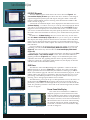
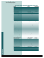
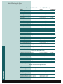
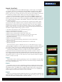
Subaru On-Board
Diagnostic
Systems
E
arly OBD (on-board diagnostic) systems, now referred to as OBD-I, could
turn on a malfunction indicator light (MIL) and store hard fault codes when
an emission-related system or component fault was detected. A hard fault is
defined as a fault that is present while the vehicle computer is monitoring a
particular circuit or device (meaning the fault is not intermittent). If the fault
went away, the MIL was turned OFF by the computer.
The Environmental Protection Agency (EPA) now has regulations in place that
establish requirements for on-board diagnostic (OBD-II) systems on light-duty
vehicles and light-duty trucks. The purpose of the OBD-II system is to ensure
proper emission control system operation for the vehicle’s lifetime by monitoring
emission-related components and systems for deterioration and malfunction.
There’s a big difference between detecting only hard faults (OBD-I) and having
the ability to actively monitor the system for proper operation, deterioration or a
malfunction (OBD-II).
Engines in today’s vehicles are largely electronically controlled. Sensors and
actuators sense the operation of specific components (e.g., the oxygen sensor) and
actuate others (e.g., the fuel injectors) to maintain optimal engine control. An on-board
computer, known as the “powertrain control module,” controls all of these systems.
The
End Wrench
Introduction
4
With proper software, the on-board computer is capable of monitoring all of the
sensors and actuators to determine whether they are working as intended. It can
detect a malfunction or deterioration of the various sensors and actuators, usually
well before the driver becomes aware of the problem through a loss in vehicle performance or driveability. The sensors and actuators, along with the diagnostic software in the on-board computer, make up what is called “the OBD-II system.”
The purpose of the OBD-II system is to assure proper emission control system
operation for the vehicle’s lifetime by monitoring emission-related components and
systems for deterioration and malfunction. There are circumstances under which
the vehicle computer will detect a system problem before the driver notices a driveability problem. Furthermore, OBD-II can detect problems that may not be noticeable upon visual inspection because many component failures that have an effect
on emissions can be electrical or even chemical in nature. By detecting these emission-related failures and alerting the driver to the need for potential repair, vehicles
can be properly repaired before emissions become a problem.
When the OBD-II system determines that a problem exists, a corresponding
Diagnostic Trouble Code (DTC) is stored in the computer’s memory. The computer
also illuminates a dashboard CHECK ENGINE light. This light serves to inform the
driver that a problem has been detected and vehicle service is needed. When the
car is delivered to the repair shop, a service technician can quickly retrieve the
stored diagnostic trouble codes from the computer memory of the vehicle using
newly developed diagnostic tools. Since the diagnostic trouble codes will specifically identify the problem, the service technician can more quickly and accurately
make the proper repair.
The following is a brief description of the Subaru OBD-II system:
• The Subaru on-board diagnostic (OBD-II) system has the ability to detect and
indicate faults in various inputs and outputs of the vehicle’s electronic control
systems. A CHECK ENGINE malfunction indicator lamp (MIL) in the combin
tion meter indicates the occurrence of a fault or trouble.
• A fail-safe function is provided to ensure minimal driveability in the event of a
failure of a component or sensor that may disable the electronic control system.
• The OBD-II system incorporated in all Subaru vehicles since 1996 complies with
Section 1968.1 of the California Code of Regulations (OBD-II regulation), and all
applicable Federal Clean Air Act regulations. The OBD-II system monitors co
ponents and system malfunctions which may have an effect on emissions.
• When the system decides that a malfunction has occurred, the MIL illuminates.
At the same time that the MIL illuminates or blinks, a diagnostic trouble code
(DTC) and freeze frame data of engine conditions are stored in the on-board
computer’s memory.
• When it detects a malfunction, the OBD-II system stores freeze frame engine
condition data (engine load, engine coolant temperature, fuel trim, engine
speed and vehicle speed, etc.) into the on-board computer memory.
• If the OBD-II system detects various malfunctions, including a fuel trim fault or
misfire, the OBD-II system first stores freeze frame engine conditions about the
fuel trim or misfire.
• If the malfunction does not occur again for three “trips,” the MIL turns off, but
the DTC remains in the on-board computer’s memory.
• The OBD-II system is capable of communication with a generic scan tool (OBD
II generic scan tool), defined by ISO 9141 CARB specifications.
• The OBD-II diagnostic procedure is different from the usual diagnostic proc
dure. When troubleshooting Subaru OBD-II vehicles, it is necessary to connect a
Subaru Select Monitor or New Select Monitor to the vehicle. If these tools are
not available, a generic OBD-II scan tool may also be used.
Subaru On-Board Diagnostic Systems
New Select Monitor
Figure 1 Original Select Monitor
Figure 2 NSM Main Menu
The Hitachi Auto Systems Company, Ltd. is the manufacturer of the Subaru
New Select Monitor (NSM). While this tool was originally supplied to Subaru dealership technicians, Hitachi has announced that it also plans to offer it to the automotive aftermarket at some time in the future.
At present, information on specific Subaru models is provided on interchangeable
data cartridges. One of the NSM’s main capabilities is to function as an OBD-II
diagnostic interface with Subaru vehicles. Since OBD-II standards and protocols
are common to all OBD-II compliant vehicles, the NSM could also be used for
OBD-II diagnosis on other vehicles. With the substitution of a “domestic” or
“generic OBD-II” data cartridge, the NSM could have the capability to function
with vehicles built by manufacturers other than Subaru.
The hand-held NSM display screen measures 95 mm by 71 mm and provides a
backlit LCD screen with adjustable contrast. Twelve functions can be displayed on
the screen at the same time and ON/OFF signals can be monitored by observing
illuminated LEDs at the side of the LCD screen. This function is similar to the original Select Monitor diagnostic tools (Figure 1), which the NSM is designed to replace.
Four channels of graphical information can be displayed at the same, with the
ability to adjust values per division and time base.
A memory feature is built in, powered by four AA batteries that maintain memory
when the NSM is turned off. Memory capacity is 256K bytes. Information stored on
the NSM can be outputted to a printer, using an infrared or conventional printer
interface. Software to download stored NSM diagnostic information to a PC will also
be offered by Hitachi.
The NSM has many features, several of which we will describe with the following
text and photographs. We’re concentrating primarily on OBD-II and engine management diagnosis in this issue of The End Wrench, so after the next three photos, we’ll be
connected to a 1997 Subaru Outback equipped with a 2.5 liter engine. The additional
capabilities of the NSM for diagnosis of other Subaru vehicle systems, as well as its
multimeter and scope capabilities, will be discussed in future issues of The End Wrench.
NSM Main Menu
Figure 3 OBD-I Diagnostic Connector
The NSM lists all of the possibilities for a particular model year range, then
attempts to communicate with all of the systems that are present on the subject
vehicle. All of the systems listed here probably won’t be present on a single
vehicle (Figure 5).
Figure 5 System Selection Menu
The
End Wrench
Figure 4 OBD-II Diagnostic Connector
After inserting the proper data cartridge and turning on the NSM, the Main
Menu comes into view (Figure 2). The NSM has the capability of monitoring and
diagnosing several Subaru vehicle systems, using the OBD-II diagnostic connector
(Figure 3). Earlier pre-OBD-II Subaru vehicles can also be accessed by the NSM,
using the proper adapter cable and the vehicle’s conventional underdash diagnostic
connector (Figure 4).
The NSM can also serve as a digital multimeter, a two channel scope meter
(actually a graphing multimeter), and it can save data to its internal memory.
The 1993 Legacy we initially connected the NSM to gave us the possibility of
access to the following vehicle systems:
• EGI/EMPI (fuel system)
• AT/ECTV (automatic transmission or electronic continuously variable transmission)
• Air Conditioning System
• Cruise Control
• ABS/TCS
• 4WS
• Air Suspension System
6
Subaru On-Board Diagnostic Systems
EGI/EMPI Diagnosis
Figure 6 EGI/EMPI Diagnosis Menu
Figure 7 12 Data Display
Figure 8 Six Data & LED Display
The EGI/EMPI Diagnosis menu allows the choices shown in Figure 6. The
Current Data Display & Store option allows the user to monitor a wide range of
engine management system inputs and outputs, using the vehicle’s serial data
interface and the OBD-II connector. A listing of the information available in this
mode is shown on page 10.
A maximum of 12 different inputs can be displayed on the NSM screen at once
(12 Data Display), so it will be necessary to scroll up or down through the data if
you want to see everything that’s being monitored by the NSM (Figure 7). Most
diagnostics will not require you to see all of the data at once, so it’s best to limit
your choices to related information only. This speeds up the unit’s refresh rate, cuts
the clutter on the LCD and makes it easier for you to monitor data from particular
inputs.
In addition to 12 Data Display, there are several other ways to look at the
data. Six Data & LED Display (Figure 8) allows you to chose up to six different
data inputs, then display them in numerical form. The status of four ON/OFF
inputs are also displayed along the right side of screen. Red LEDs turn ON or
OFF to indicate the status of these inputs. This function is similar to the original
Select Monitor.
If you’re looking for an input that may be going out of range or want to track
something over time, the Four Data Display With Max & Min may be selected
(Figure 9). This feature may also be reduced to One Data Display With Detail
(Figure 10).
Data may also be presented in a graphical format by switching over to the Four
Channel Graph or Two Channel Graph screens. This converts the NSM into a
graphing multimeter (Figure 11). The voltage scale of individual inputs can be
adjusted in this mode. The graphing function can be especially useful if you’re
looking for a glitch in a signal. If the glitch should occur, the display can be held
and the results saved to the NSM’s memory.
OBD Menu
Figure 9
Four Data Display With Max & Min
The NSM also offers full OBD-II diagnostic capabilities. A menu of the unit’s
OBD-II functions is shown in Figure 12. A complete list of the Current Data
Display parameters that are monitored by the NSM for a 1998 Legacy in OBD-II
mode can be found on page XX. This list is shown for illustrative purposes, as other
Subaru vehicles may have more parameters, and some may have less. For a complete listing of the OBD-II parameters for the particular Subaru vehicle you are
servicing, refer to the appropriate Subaru service manual.
The NSM allows you to look at up to 12 data parameters at once, the same as in
the Normal mode (Figure 13). Because there will always be more than 12 data
parameters, you’ll need to scroll through the list if you want to see them all in this
mode. If a particular parameter is not found on the vehicle being tested, the NSM
will list “no support.”
Freeze Frame Data Display
Figure 11 Graphing Multimeter
Figure 12 OBD Menu
The
End Wrench
Figure 10 One Data Display With Detail
8
One of the most useful features of OBD-II for
diagnostic purposes is Freeze Frame Data. If the
vehicle’s OBD-II system detects a fault that might
cause increased vehicle emissions or might damage
the catalytic converter, it stores freeze frame data at
the moment the fault occurred. So instead of being
left with just a Diagnostic Trouble Code (DTC) to
work with, we also have freeze frame data to help
us with our diagnosis.
Diagnostic Trouble Codes (DTC) Display
OBD-II regulations require the use of standardized DTCs. There’s no longer a
need to learn the diagnostic language of individual vehicle manufacturers.
Diagnostic Trouble Code (DTC) definitions and numbers were prescribed by the
Society of Automotive Engineers (SAE) under J2012.
Powertrain DTCs beginning with the prefix “P0” have standardized meanings
and may be used by all vehicle manufacturers. Powertrain DTCs beginning with the
prefix “P1” are considered “manufacturer specific” and may be used to define systems or functions that are unique to a particular manufacturer or a vehicle from that
manufacturer.
While this system of identification eliminates most of the confusion surrounding
DTC definitions, it also multiplies the number of available DTCs for a particular
vehicle by several fold. We checked the powertrain DTC list for a late model Subaru
Legacy and found there were over 100 possibilities. There’s no way you’re going to
be able to memorize all those DTCs, so reliable service information becomes even
more important than it has been in the past.
We intentionally triggered several DTCs to produce the list of DTCs shown in
Figure 14. DTCs can also be cleared using the NSM, but be advised that the freeze
frame data that goes along with the DTCs will be erased at the same time.
Figure 13 12 Data Parameter Display
Figure 14 Stored DTC Display
Other OBD Mode Features
The NSM can also access the PCM to monitor O2 sensor operation (O2 Sensor
Monitor Test). Information obtained during this test includes rich-to-lean and leanto-rich threshold voltages and times, and low/high sensor voltages for switch time
calculations (Figure 15). This data can be especially useful if a “lazy” or dying
oxygen sensor is suspected. The numbers shown here don’t lie.
Some DTCs are considered to be temporary, meaning they haven’t yet met the
criteria to trigger the Malfunction Indicator Light (MIL). Perhaps a fault was detected
just once, then not repeated. While this may not be enough to trigger the MIL, it
doesn’t mean the PCM’s OBD-II function looks the other way. Quite the contrary.
The PCM will store this information under a temporary DTC. If the conditions that
triggered the original temporary DTC are not repeated for a prescribed number of
vehicle “trips,” the PCM will eventually strike the temporary DTC from its memory.
Until the PCM’s set of code removal requirements is met, any stored temporary
DTC can be viewed under the Temporary Codes Inspection mode on the NSM. This
mode can be very useful when diagnosing intermittent problems that refuse to reveal
themselves during normal troubleshooting activities.
Figure 15 Oxygen Sensor Monitor
System Operation Check Mode
Figure 17 Green Check Connectors
The last NSM function we’re going to look at is the System Operation Check
Mode (Figure 16). Connecting the two green underdash Check connectors (Figure
17) places the vehicle in “Check Mode.” When the ignition is turned ON, the CHECK
ENGINE light on the Combination Meter will begin flashing OFF and ON and several fuel system and emission components will begin cycling OFF and ON.
This mode can be useful for checking the operation of specific components. Using
the NSM and the underdash Check connectors, it’s possible to test one component at
a time. We selected the A/C Compressor Relay (Figure 18), then took the NSM
under the hood to listen for the compressor clutch to cycle OFF and ON (Figure 19).
Selecting one component at a time allows you to more closely. If the component
cycles OFF and ON as it should, you can be certain that the wiring between the component and the PCM are okay. Running through each system operation check doesn’t
take long and eliminates a lot of guesswork. Don’t forget to disconnect the Check
connectors when you’re done.
Figure 16
System Operation Check Mode
Figure 18 Actuator ON/OFF Menu
Figure 19
Monitoring A/C Relay Operation
9
Subaru On-Board Diagnostic Systems
Contents
Display
Unit of Measure
Battery Voltage
Battery Voltage
V
Vehicle Speed Signal
Vehicle Speed
km/h or MPH
Engine Speed Signal
Engine Speed
RPM
Engine Coolant Temperature Sensor Signal
Coolant Temperature
°C or °F
Ignition Timing Signal
Ignition Timing
degrees
Mass Air Flow Signal
Mass Air Flow
g/s or lb/m
Mass Air Flow Signal
Air Flow Sensor Voltage
V
Throttle Position Signal
Throttle Opening Angle
%
Throttle Position Signal
Throttle Sensor Voltage
V
Injection Pulse Width
Fuel Injection #1 Pulse
ms
Idle Air Control Signal
ISC Valve Duty Ratio
%
Engine Load Data
Engine Load
%
Front Oxygen Sensor Output Signal
Front O2 Sensor
V
Rear Oxygen Sensor Output Signal
Rear O2 Sensor
V
Short Term Fuel Trim
A/F Correction #1
%
Knock Sensor Signal
Knocking Correction
degrees
Atmospheric Absolute Pressure Signal
Atmospheric Pressure
mmHg/kPa/InHg
Intake Manifold Absolute Pressure Signal
Manifold Relative Pressure mmHg/kPa/InHg
A/F Correction (short term fuel trim) By Rear O2 Sensor
Rear O2 A/F Learning
%
Long Term Fuel Trim
Whole A/F Learning
%
Long Term Whole Fuel Trim
Front O2 A/F Learning
%
Front Oxygen Sensor Heater Current
Front O2 Heater
A
Rear Oxygen Sensor Heater Current
Rear O2 Heater
A
Canister Purge Control Solenoid Valve Duty Ratio
CPC Valve Duty Ratio
%
Fuel Tank Pressure Signal
Fuel Tank Pressure
mmHg/kPa/InHg
Fuel Temperature Signal
Fuel Temperature
°C or °F
Fuel Level Signal
Fuel Level
V
Ignition Switch Signal
Ignition Switch
ON or OFF
Automatic Transmission Vehicle Identification Signal
AT Vehicle ID Signal
ON or OFF
Test Mode Connector Signal
Test Mode Signal
ON or OFF
Neutral Position Switch Signal
Neutral Position Switch
ON or OFF
Air Conditioning Switch Signal
A/C Switch
ON or OFF
Air Conditioning Relay Signal
A/C Relay
ON or OFF
Radiator Main Fan Relay Signal
Radiator Fan Relay #1
ON or OFF
Fuel Pump Relay Signal
Fuel Pump Relay
ON or OFF
Knocking Signal
Knocking Signal
ON or OFF
Radiator Sub Fan Relay Signal
Radiator Fan Relay #2
ON or OFF
Engine Torque Control Signal
Torque Control Signal
ON or OFF
Pressure Sources Switching Solenoid Valve
Pressure Sources Change
ON or OFF
Front Oxygen Sensor Rich Signal
Front O2 Rich Signal
ON or OFF
Rear Oxygen Sensor Rich Signal
Rear O2 Rich Signal
ON or OFF
Federal Specification Vehicle Identification Signal
FED Spec. Vehicle Signal
ON or OFF
Exhaust Gas Recirculation System Diagnosis Signal
EGR System Diagnosis
ON or OFF
Catalyst Diagnosis Signal
Catalyst Diagnosis
ON or OFF
Pressure Control Solenoid Valve
PCV Solenoid Valve
ON or OFF
Exhaust Gas Recirculation Solenoid Valve
EGR Solenoid Valve
ON or OFF
Vent Control Solenoid Valve
Vent Solenoid Valve
ON or OFF
The
End Wrench
New Select Monitor Current Engine Data Display (Normal Mode)
10
Subaru On-Board Diagnostic Systems
New Select Monitor Current Data (OBD Mode)
Contents
Display
Number Of Diagnostic Code
Number Of Diagnostic Code —
Unit of Measure
Malfunction Indicator Lamp Status
MIL Status
Monitoring Test Of Misfire
Misfire Monitoring
ON or OFF
Monitoring Test Of Fuel System
Fuel System Monitoring
ON or OFF
Monitoring Test Of Comprehensive Component
Component Monitoring
ON or OFF
Test Of Catalyst
Catalyst Diagnosis
ON or OFF
Test Of Heated Catalyst
Heated Catalyst
ON or OFF
Test Of Evaporative Emission Purge Control System
Evaporative Purge System
ON or OFF
Test Of Secondary Air System
Secondary Air System
ON or OFF
Test Of Air Conditioning System Refrigerant
A/C System Refrigerant
ON or OFF
ON or OFF
Test Of Oxygen Sensor
Oxygen Sensor
ON or OFF
Test Of Oxygen Sensor Heater
Oxygen Sensor Heater
ON or OFF
Test Of Exhaust Gas Recirculation System
EGR System Diagnosis
ON or OFF
Air Fuel Ratio Control System For Bank 1
Fuel System For Bank 1
ON or OFF
Engine Load Data
Engine Load
%
Engine Coolant Temperature Signal
Coolant Temperature
°C or °F
Short Term Fuel Trim By Front Oxygen Sensor
Short Term Fuel Trim B1
%
Long Term Fuel Trim By Front Oxygen Sensor
Long Term Fuel Trim B1
%
Intake Manifold Absolute Pressure Signal
Manifold Absolute Pressure mmHg/kPa/InHg
Engine Speed Signal
Engine Speed
RPM
Vehicle Speed Signal
Vehicle Speed
km/h or MPH
Ignition Timing Advance For #1 Cylinder
Ignition Timing Advance #1 °
Mass Air Flow Signal
Mass Air Flow
Throttle Position Signal
Throttle Opening Angle
%
Front Oxygen Sensor Output Signal
Oxygen Sensor #11
V
Air Fuel Ratio Correction By Front Oxygen Sensor
Short Term Fuel Trim #11
%
Rear Oxygen Sensor Output Signal
Oxygen Sensor #12
V
Air Fuel Ratio Correction For Rear Oxygen Sensor
Short Term Fuel Trim #12
%
On-board Diagnostic System
OBD System
—
g/s or lb/m
Freeze Frame Data (OBD Mode)
Diagnostic Trouble Code (DTC) For Freeze Frame Data
Freeze Frame Data
DTC
Air Fuel Ratio Control System For Bank 1
Fuel System For Bank 1
ON or OFF
Engine Load Data
Engine Load
%
Engine Coolant Temperature Signal
Coolant Temperature
°C or °F
Short Term Fuel Trim By Front Oxygen Sensor
Short Term Fuel Trim B1
%
Long Term Fuel Trim By Front Oxygen Sensor
Long Term Fuel Trim B1
%
Intake Manifold Absolute Pressure Signal
Manifold Absolute Pressure mmHg/kPa/InHg
Engine Speed Signal
Engine Speed
RPM
Vehicle Speed Signal
Vehicle Speed
km/h or MPH
The
End Wrench
Oxygen Sensor Monitoring Test Results
Oxygen Sensor For Monitoring Test
<O2 Sensor Monitor (---)>
—
Rich To Lean Oxygen Sensor Threshold Voltage
Rich To Lean Sensor Volt
V
Lean To Rich Oxygen Sensor Threshold Voltage
Lean To Rich Sensor Volt
V
Low Oxygen Sensor Voltage For Switch Time Calculation Low Sensor Voltage
V
High Oxygen Sensor Voltage For Switch Time Calculation High Sensor Voltage
V
Rich To Lean Oxygen Sensor Switch Time
Rich To Lean Switch Time
sec
Lean To Rich Oxygen Sensor Switch Time
Lean To Rich Switch Time
sec
Maximum Oxygen Sensor Voltage For Test Cycle
Maximum Sensor Voltage
V
Minimum Oxygen Sensor Voltage For Test Cycle
Minimum Sensor Voltage
V
12
Generic Scan Tools
One of the biggest advances that OBD-II brought to vehicle repair was the ability
of a “generic scan tool” to communicate with any OBD-II compliant vehicle. OBD-II
regulations spell out a specific way that all vehicles must communicate with these
generic scan tools. It’s no longer necessary to have a drawer full of adapters and testers
to communicate with the various vehicles your shop may happen to work on.
Since all 1996 and later Subaru vehicles must comply with OBD-II regulations, we
decided to try out an assortment of generic scan tools on an OBD-II compliant 1995
Subaru Legacy. The Legacy came on line with OBD-II capability during the 1995 model
year, while the Impreza made the 1996 deadline. All Forester and Outback models are
also OBD-II compliant
None of the generic scan tools we tested offer the versatility and wealth of data
found in the New Select Monitor. Unless you plan on doing an awful lot of Subaru
OBD-II repairs, you may not be able to justify the expense of a New Select Monitor
purchase. If you already own or plan to purchase a generic scan tool with OBD-II
updates, at the very least, you will be able to retrieve the following information from
an OBD-II compliant Subaru using a generic scan tool:
• Automatic determination of the communications protocol.
• Display of the Readiness Test status.
• Display of the vehicle’s Current Data parameters.
• Display of Freeze Frame Data saved by the control unit.
• Display of Diagnostic Trouble Codes (DTCs) saved by the control unit.
• Clearing Emission-Related Diagnostic Information (DTCs and
diagnostic parameters).
• Display of O2 Sensor Test Results.
• Display of the On-Board Monitoring Test Results for Non-Continuously
Monitored Systems.
• Display of the On-Board Monitoring Test Results for Continuously
Monitored Systems.
We tried out three “generic” OBD-II scan tools on a 1995 Subaru Legacy wagon.
Although OBD-II compliance was not required by EPA regulations until the 1996 model
year, Legacy models began receiving OBD-II equipment during the 1995 model year.
The 1995 Legacy wagon we used for our testing was fully OBD-II compliant.
The three generic OBD-II scan tools we tried out were the OTC Monitor 4000
Enhanced, the Vetronix Mastertech and the Snap-on Scanner. All three scanners
successfully interfaced and retrieved information from our Subaru wagon, but each
took a slightly different method to get there. All three scanners have the ability to save
information, print it, or store it to a PC. We’ll use a series of photos and short captions
to show you what we found.
Figure 1
Figure 1
Aftermarket scanner software typically lags a year or two behind the current vehicle
model year. This Import `96 cartridge is the most recent data cartridge available for the
OTC Monitor 4000 Enhanced.
Figure 2
The Monitor asks you a series of qualifying questions to identify the vehicle. These
questions are necessary because the data cartridge contains information on both OBD-I
and OBD-II vehicles. An OBD-II only cartridge wouldn’t need to know what type of
vehicle you were working on, because the data exchange protocols are standardized
and the diagnostic link connector (DLC) is always the same.
Figure 3
When we got through with the qualifying questions, we found that the Monitor had
OBD information on the Engine/PCM, as well as the ABS and Airbag systems. The ABS
and Airbag information dealt primarily with DTC retrieval.
13
Figure 2
Figure 3
Subaru On-Board Diagnostic Systems
Figure 4
The Vetronix Mastertech offers a generic OBD-II cartridge. This means that it’s unnecessary to answer any
qualifying questions. Just plug the unit’s diagnostic connector into the DLC and you’re ready to go. After communicating with the vehicle’s PCM, the Mastertech tells
you what OBD-II options are available for the vehicle
Figure 4
Figure 5
The Mastertech’s large LCD allows you to simultaneously view up to 12 different
current data points. Scrolling up or down allows you to see all of the available data.
Figure 6
ll generic scan tools must be able to display the results of
the OBD-II Readiness Tests. All Readiness Tests for
Continuous and Non-Continuos Monitors are displayed
on the same screen. Our 1995 Legacy is not equipped
with all of the possible OBD-II monitors, so the
Mastertech showed “N/A” for these.
Figure 5
Figure 6
Figure 7
If the OBD-II system has stored a DTC, snapshot data will also be stored in the PCM
memory. The Mastertech has its own snapshot capability, that is similar to the PCM’s
function. In Snapshot mode, the Mastertech can capture a sequence of data parameters that you define. Road testing the vehicle in this mode may allow you to capture
an intermittent fault.
Figure 8
The Snap-on Scanner relies on a pair of data cartridges: a
primary data cartridge and a Fast Track Troubleshooter cartridge that contains additional OBD-II diagnostic information. These cartridges will take you through 1997 model
year import vehicles.
Figure 7
Figure 8
Figure 9
Because the Scanner handles OBD-I and OBD-II vehicles, a series of qualifying questions are required to let the Scanner know which vehicle it’s hooked up to. The scanner relies on VIN information to zero in on the specific Subaru model. If you want to
bypass this routine, it’s possible to take the “OBD Generic” menu option.
The
End Wrench
Figure 10
The Snap-on Scanner requires the use of a “key” in its
OBD-II diagnostic connector to fine-tune the Scanner to the
vehicle that is being tested.
Figure 9
Figure 10
Figure 11
OBD-II Current Data parameters are displayed six at a time across the Scanner’s LCD.
Scrolling with the unit’s thumbwheel takes you through all parameters.
All other generic OBD-II scanner functions are also supported by the Snap-on Scanner.
14
Figure 11