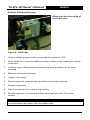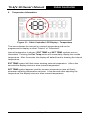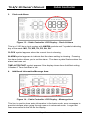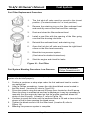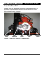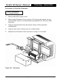
1
Owner's Manual Model: MTS-T4-6 Model: MTS-T4-V10 T4-6/V-10 Owner's Manual Preface Congratulations on your purchase of the RigMaster Auxiliary Power Unit. RigMaster is a totally self contained, stand-alone generator, Air Conditioner and Heater System. The only items that are shared with your Truck Systems are fuel and battery supply. The RigMaster unit also trickle charges the Truck batteries while in operation. Superior design and performance have been incorporated into this product to give you trouble-free, economical operation. We are confident you will be satisfied with your new RigMaster Auxiliary Power Unit. The following pages contain design features, principles of operation, preventative maintenance procedures and troubleshooting guides. Please review it carefully prior to starting and operating your RigMaster Unit. For safety’s sake, please also heed all safety warnings and advisories found within your Owner’s Manual. Should you have any questions or concerns please contact your nearest authorized RigMaster Power Dealer, or RigMaster Power International Ltd. at: 1-888-208-3101 (For technical support only) Monday to Friday from 8:00 a.m. to 5:00 p.m. Eastern Standard Time Or Visit Our Website: www.rigmasterpower.com Click: Customer Support, Support Materials, Technical Support (For Other Technical Information) Page 1 T4-6_V10-Owners-Manual-121814 T4-6/V-10 Owner's Manual Preface Definitions NOTE A NOTE describes important information necessary to properly complete a procedure, or information which will make the procedure easier to understand. CAUTION A CAUTION describes a special procedure or special steps which must be taken while completing a task. Disregarding a CAUTION may result in damage to the assembly. WARNING! A WARNING describes a special procedure or steps, which must be taken while completing the procedure where the warning is found. Disregarding a WARNING can result in serious personal injury or death. Page 2 T4-6_V10-Owners-Manual-121814 T4-6/V-10 Owner's Manual Preface Additional Publications “Model T4-6 and V10 Service Manual” “Model T4-6 and V10 Installation Manual” See your Perkins or Caterpillar Dealer for these other publications: Perkins Service Manual 400C Series; Part Number RENR9825 The tier 4a engine model 400D Series Perkins; User’s Hand Book, 400 Series, Part Number 100816245 Caterpillar: C0.5 Industrial Engine Service Manual Licensed dealerships may review and download additional publications by logging into their Dealer portal. NOTE Owner’s Manuals and APU Parts Lists are publicly accessible and downloadable: go to www.rigmasterpower.com hold your cursor over the “customer support tab” and select “support materials” On this web page, also note “PARTS LISTS - ALL MODELS AS OF (DATE)”— this lists all parts ever used in our APU’s. All parts are available to order. This Manual is divided into sections by engine and assembly systems, with a section dedicated to the preventative maintenance of the APU. For detailed information on installation please refer to the “model T4-6 and V10 Installation Manual”. For detailed information on engine service please refer to either the Perkins or Caterpillar Service Manual. Read this entire Manual prior to performing service and maintenance procedures. If you do not fully understand how to perform a process or procedure or require additional help please contact our Technical Support Department before proceeding. Technical Assistance Before calling for technical assistance please have ready the following: 1. Current T4-6 / V10 Service Manual 2. Model T4-6 or V10 Serial Number 3. Unit Hour Meter Reading 4. Service & Repair History (if available) Technical support is available by Telephone: (888) 208-3101 or (416) 201-0040 Monday to Friday from 8:00 a.m. to 5:00 p.m. Eastern Standard Time and Website: www.rigmasterpower.com Click: Customer Support, Support Materials, Technical Support Page 3 T4-6_V10-Owners-Manual-121814 T4-6/V-10 Owner's Manual Table of Contents Table of Contents Principles of Operation Page # Preface – Additional Publications/Technical Assistance 1 Safety 5 Heater 7 Air Conditioner 10 120-Volt Generator 12 Pre-Start Inspection 13 Cabin Controller Description and Operating Instructions 14 Clock and Date Set-Up 20 Set Alarm Clock 21 AutoStart Features 22 FAULT CODES 24 Fuel System Description and Bleeding Procedures 28 Preventative Maintenance Schedule 34 Cross Reference Parts List 35 Normal Maintenance & Adjustment Instructions Oil Change Instructions 36 Air Filter Change Instructions 40 Serpentine Drive Belt – Removal 41 Fan Belt – Removal and Adjustment 43 Breaker Reset Instructions 45 Cleaning Instructions 47 Cleaning – Generator 48 Cleaning – HVAC Filter 50 Troubleshooting 51 Warranty RigMaster APU Limited Warranty 57 Maintenance Record 63 Notes 65 Page 4 T4-6_V10-Owners-Manual-121814 T4-6/V-10 Owner's Manual Safety 1. Zero Energy State NOTE: ZERO ENERGY STATE To perform service, maintenance and repairs you must disconnect the RigMaster from its battery source. In the recommended installation configuration the RigMaster shares the battery bank with the vehicle's main engine. Unplug the J1 harness at the power module before disconnecting the battery cables. After disconnecting the battery cables, check the battery posts inside the RigMaster engine cabinet to confirm there is no voltage to the auxiliary power unit (APU). 2. Safety Cover Switch WARNING!: SAFETY COVER SWITCH It is critical that this safety cover switch is never bypassed; failure to comply may result in serious injury. Safety Cover Switch The safety cover switch (Figure 1) is designed to prevent the RigMaster Power APU from starting when the engine cover is loose or has been removed. When the cover is down, the switch is in the closed position. When the cover is open or loose, the switch is in the open position. The switch is located at the very top of the unit enclosure on the surge tank bracket. Figure 1 – Safety Cover Switch 3. AutoStart Automatic Start/Stop Feature CAUTION: AUTOSTART FEATURE Remember that a properly functioning RigMaster is capable of starting independently of its operator. If the AutoStart feature is enabled, battery voltage, temperature, and time of day can all cause the RigMaster’s engine to start. Please see the cabin controllers operating instructions for further information on the AutoStart feature. You must deactivate this feature prior to refueling. Page 5 T4-6_V10-Owners-Manual-121814 T4-6/V-10 Owner's Manual Safety 4. Engine Hoist Points NOTE: ENGINE HOIST POINTS The Perkins and CAT engines have hoist points that are useful for removal and reinstallation of the engine. Under no circumstances should the entire RigMaster APU assembly be lifted by the engine hoist points as they are not intended to hold the increased weight of the engine with fluids, frame and other on-board equipment. 5. Starting Aids WARNING! Do not use any type of starting aids such as ether or “Quick Start”. Such use could result in an explosion and personal injury, and will render the APU warranty null and void. 6. Starting with the Cover Off CAUTION Some installation or repair/diagnostic procedures require that the APU is started with the engine cover off. Do not deactivate or bypass the safety cover switch. Instead, have another individual assist by manually holding the safety cover switch down in the closed position for the duration of the procedure. 7. Inspection of the Safety Systems The safety systems on the RigMaster APU should be examined and tested prior to performing any service work and at 50 hour intervals to ensure that they are in good condition and proper working order. 8. Safe Working Practices Safe working practices are your responsibility. The use of protective safety equipment is mandatory when performing inspections, service, diagnostics and repairs on the RigMaster APU. Follow your local regulations and guidelines regarding occupational health and safety. 9. Contact Us If you do not fully understand this safety information contact RigMaster’s Technical Support Department toll free at (888) 208 – 3101 before proceeding with the operation or service of this APU. Page 6 T4-6_V10-Owners-Manual-121814 T4-6/V-10 Owner's Manual Heater Heater The RigMaster heating system is fully automatic. A constant comfort zone is maintained with the temperature selector (see Cabin Controller Operation – Page 14). The bunk heating system is a complete stand alone system that is not integrated into the vehicle's cooling system. When heat is selected, and the RigMaster is in operation, the hot coolant flows through the heater core (installed under the bunk – see Figure 2). The heater/air conditioner blower motor (fan) circulates the cab air through the heater core pushing warm air into the bunk area. The coolant is then recirculated back to the RigMaster Unit. NOTE Plugging in the block heater places a load of approximately 1,500 watts on the engine; this load enables the engine to heat the coolant. This system is designed to maximize the bunk heating efficiency. Thermostat 82 °C Radiator Water Pump Heater Core Engine Red – High Temperature Supply Lines Blue – Lower Temperature Return Lines Figure 2 – Heater Page 7 T4-6_V10-Owners-Manual-121814 T4-6/V-10 Owner's Manual Heater Heating System For heating, the APU’s coolant flow is directed into the HVAC box mounted inside the bunk. A water valve mounted to the HVAC box regulates the flow of coolant through the heater core. Voltage at the J2 Connector Pin-1 on the power module will indicate if the water valve is open or closed. (Closed=0 volts / Open=12.4 volts). Figure 3 – Heating System NOTE Notice the coolant flow when the valve is open. The coolant will travel to the HVAC box and then return on the opposite copper pipe. Electronic Coolant Control Valve The electronic coolant control valve motor shaft is a good indication if the valve is opening when changing temperature modes. Marking the shaft with a black marker which will make the shaft rotation more visible. When the valve is closed coolant will loop back to the engine. Figure 4 – Control Valve Motor Shaft Page 8 Figure 5 – Loop back to Engine T4-6_V10-Owners-Manual-121814 T4-6/V-10 Owner's Manual Heater Radiator Filling and Purging Bleed from the return side of the heater core. Figure 6 – HVAC Box 1. Using a radiator pressure tester, pressurize the system to 7 PSI. 2. At the HVAC box, loosen the left hose clamp located on the copper pipe closest to the filter. 3. Carefully insert a flat screwdriver between the hose and tube until air starts escaping. 4. Bleed air until coolant escapes. 5. Tighten hose clamp. 6. Remove pressure tester and top up radiator and coolant reservoir. 7. Repeat if necessary. 8. Start the engine and turn heat on high setting. 9. Run the engine for 15 minutes and then allow engine to cool. Top up the coolant. NOTE When purging the air from the HVAC box use some lubricant on the screw driver to slide between the copper tube and rubber hose. Page 9 T4-6_V10-Owners-Manual-121814 T4-6/V-10 Owner's Manual Air Conditioner Air Conditioner The RigMaster air conditioner is also fully automatic. A constant comfort zone is maintained with the temperature selector setting (see Cabin Controller Operation – Page 14). The RigMaster air conditioner is an R134A system that is not integrated into the vehicle's existing air conditioning system. WARNING! ONLY CERTIFIED AIR CONDITIONING TECHNICIANS SHOULD SERVICE THE AIR CONDITIONER. HIGH PRESSURE VS. TEMPERATURE READINGS High temperatures and pressures are approximate. Readings within 10-15% of Figure 7 will deliver acceptable performance. Air Conditioning Performance Figure 7 – A/C Performance SUCTION PRESSURES – LOW SIDE Usual low side pressure 15-40 PSI depending on outside temperature and humidity. DISCHARGE PRESSURES – HIGH SIDE Usual high side pressure 150-300+ PSI depending on outside temperature and humidity. AIR CONDITIONING SPECIFICATIONS Refrigerant Type Volume of Refrigerant - (20,000 BTU HVAC) Compressor Oil Type Compressor Oil Capacity (already filled with 7 oz.; add an extra 1 oz. at time of charging) Evaporator Temperature Switch Binary Pressure Switch R134a 2.2 lbs.; (35.2 oz.; 1 Kg.) SP46 to 100 PAG Compressor Oil Page 10 8 fl. oz.; (236.5 cc.; 236.5 mL.) Range = 30°F to 42°F (-1°C to 5°C) Range = 28 to 450 psi T4-6_V10-Owners-Manual-121814 T4-6/V-10 Owner's Manual Air Conditioner The compressor within the RigMaster unit pumps the refrigerant gas through the condenser that dissipates the heat and changes the refrigerant from a gas to a liquid. The liquid refrigerant passes through a filter (receiver drier), and then through the evaporator core located in the bunk heater/air conditioner unit. The heater/air conditioner blower motor (fan) then activates, and cool dry air is forced into the bunk area. Figure 8 – Air Conditioner A B C D E F G H I J K L M LEGEND Condenser Compressor Receiver Drier Evaporator Thermostatic Switch Frame A/C Line – Evaporator to Bulkhead – #6 A/C Line – Evaporator to Bulkhead – #10 A/C Line – Receiver Drier to Bulkhead –#6 A/C Line – Compressor to Bulkhead – #10 A/C Line – Condenser to Receiver Drier #6 A/C Line – Compressor to Condenser – #8 Expansion Valve Page 11 PRESSURE High High/Low High High High/Low N/A High Low High Low High High High/Low PART # RP9-011 RP9-132 RP9-027B RP9-201 RP9-113 RP10-001-01 RP9-405 RP9-404 RP9-403 RP9-401 RP9-402 RP9-400 RP9-112 T4-6_V10-Owners-Manual-121814 T4-6/V-10 Owner's Manual 120-Volt Generator 120-Volt Generator The 6kW heavy-duty generator is located at the rear of the RigMaster unit and is belt driven at 3600 RPM. The generator has two (2) factory supplied cords. One (1) block heater cord (complete with a plug), allows the vehicle's block heater to be plugged into the generator. This ensures that the vehicle's main engine will be warm when starting in cold weather. This provides a load on the RigMaster engine that allows the unit to run more efficiently and prolong the RigMaster's service life. The block heater connection uses one (1) 20 AMP breaker. It is recommended that the RigMaster remain plugged into the vehicle's block heater throughout the winter months and unplugged for the spring and summer months. A second 20 AMP supply of 120V power is supplied for the driver’s convenience. A multiple outlet cord is supplied and can be installed in the bunk area of the vehicle to provide power for 120V appliances. Figure 9 – Generator NOTE Each 20 Amp Breaker has a capacity of 2400 Watts. Page 12 T4-6_V10-Owners-Manual-121814 T4-6/V-10 Owner's Manual Pre-Start Inspection Pre-Start Inspection with the RigMaster TURNED OFF 1. Remove the cover. 2. Visually inspect the unit for evidence of oil or coolant leakage. 3. Check the oil and add oil if necessary. 4. Check the tension and wear of all belts. 5. Check the mounting bolts and tighten if necessary. 6. Check for broken, corroded, or loose connectors and/or wires. 7. Check the physical condition and tightness of all hoses and hose clamps. 8. Replace and secure the cover. Page 13 T4-6_V10-Owners-Manual-121814 T4-6/V-10 Owner's Manual Cabin Controller Cabin Controller Operating Instructions Before beginning the start-up procedure it is necessary to know how to operate the cabin controller. Figure 10 – Cabin Controller Controls The Cabin Controller consists of two sections: 1. LCD (Liquid Crystal Display) with basic control buttons. 2. Advanced control buttons. The LCD and basic control buttons are always visible to the user. The advanced control buttons are concealed behind a semi-circular cover. The controller also contains a LED indicator. When the LED is green, the system is active; if it glows red then the system is detecting a problem and an error message will scroll across the bottom of the LCD screen. The LED is turned off in low power mode. 1. Basic Controls and Functions Basic controls contain the following buttons: 1. Start system. 2. Stop system. 3. Up arrow (Red triangular button). 4. Down arrow (Blue triangular button). Page 14 T4-6_V10-Owners-Manual-121814 T4-6/V-10 Owner's Manual Cabin Controller If the unit is in advanced mode, pressing any of the basic control buttons will return the unit to basic mode. Alternately, the control panel will return to basic mode after two minutes of inactivity. If the unit shows the current temperature, pressing either the up or down button will show the set point temperature without changing it. Once the set point is indicated, pressing up or down buttons will adjust the set point. The new set point takes effect only when display is returned to show internal temperature. 2. Advanced Controls and Functions The advanced controls are as follows: 1. Power button controls whether the module is active. In inactive mode all system functions including engine start, climate control and AutoStart are disabled. You can still see the temperature reading, current time and use the alarm clock function. 2. Fan button is used to change fan setting. Pressing the button cycles between auto, high, med, low, and off settings. 3. Clear button will take you back to the main screen without saving any information. 4. Clock button is used to set the time/date/day menu features. 5. Alarm button is used to set the alarm menu features. 6. AutoStart button is used to access and set AutoStart menu features. 7. Mode button is used to activate the different operational modes. Pressing the mode button will back you out of a menu mode, but does not save the information just entered. 8. Ext. Temp button will display the external temperature on the LCD when pressed. 9. Oprtg. Hours button will display the total hours of use. 10. Select button enters the data and advances the program to the next menu step. Pressing the select button will save the information when entering operational data. 11. Left scroll button (). 12. Right scroll button (). The left and right arrow buttons are used to locate the desired data and/or adjust those values. Page 15 T4-6_V10-Owners-Manual-121814 T4-6/V-10 Owner's Manual Cabin Controller Cabin Controller LCD Display The Cabin Controller LCD has a white backlight that turns on each time a user presses a button and will remain on for 2 minutes after the last button has been pushed. The backlight will turn red when there is an alarm condition. A fault code will be displayed if the unit shuts down or fails to start. The LCD displays 4 groups of information: 1. System information. 2. Temperature information. 3. Clock, day and alarm information. 4. Alphanumeric display for additional information. 1. System Information: Figure 11 – Cabin Controller LCD Display – Controls SYSTEM ALARM symbol will flash if an alarm condition has occurred. The alphanumeric display along the bottom of the display screen will show more information about the alarm. (Red status LED will be on.) SYSTEM ON symbol will display if the unit is in ON mode. (Green status LED will be on.) ENGINE RUNNING symbol will display when the engine is running. AUTOSTART symbol will display and flash if temperature AutoStart is enabled (when engine is off). If the engine has been started through AutoStart, this symbol is constantly on while the engine is running. HEATING symbol will display when the system is in heating mode. COOLING symbol will display when the system is in cooling mode. FAN AUTO, FAN HIGH, FAN MED, or FAN LOW symbol will display depending on which setting has been selected. Nothing will display in this area if the fan is set to off. Page 16 T4-6_V10-Owners-Manual-121814 T4-6/V-10 Owner's Manual 2. Cabin Controller Temperature Information: Figure 12 – Cabin Controller LCD Display – Temperature This area indicates the internal (or external) temperature and can be programmed to display in either “Celsius” or “Fahrenheit”. Internal temperature is shown if EXT TEMP and SET TEMP symbols are not illuminated. Pressing the Ext. Temp button will momentarily display the outside temperature. After 5 seconds, the display will default back to showing the internal temperature. EXT TEMP symbol will flash when showing external temperature. After a few seconds the display returns to show internal temperature. SET TEMP symbol appears (and the numeric temperature value will flash) whenever adjusting temperature set point. A few seconds after adjusting the temperature, the display returns to show internal temperature. Page 17 T4-6_V10-Owners-Manual-121814 T4-6/V-10 Owner's Manual 3. Cabin Controller Clock and Alarm: Figure 13 – Cabin Controller LCD Display – Clock & Alarm This is a 12:00 hour clock system with AM/PM symbols and 7 symbols indicating day of the week: MO, TU, WE, TH, FR, SA, SU. CLOCK symbol appears when the current time is showing. ALARM symbol appears to indicate that the alarm setting is showing. Pressing the alarm button allows you to set the alarm. The alarm symbol flashes when the alarm has been set. TIME AUTOSTART symbol appears if the display shows time AutoStart setting. It flashes if Time AutoStart is set. 4. Additional Information/Message Area: Figure 14 – Cabin Controller LCD Display – Message Area This line is used to show extra information in the basic mode; error messages to provide interface when going through menus in advanced mode. Longer text lines are scrolled to the left on the display. Page 18 T4-6_V10-Owners-Manual-121814 T4-6/V-10 Owner's Manual Cabin Controller Operation of the Cabin Controller (Functions) To Turn Power On Press the POWER button to activate the system. When the power switch is activated the LCD display will light and SYSTEM ON symbol will turn on (active mode). Press POWER button again for 2 seconds to switch the unit back to low power mode. Engine Start Press START button. The control panel will display the status of the operation as it occurs: Glow Plug and a countdown will display on the screen. Once the countdown is complete the display will read Cranking as the APU starts up and the ENGINE RUNNING symbol will blink. Once started the control will display Engine Running for 5 seconds (and ENGINE RUNNING symbol will turn on). Engine Stop Press STOP button. The screen will initially display Stopping and then change to Stopped once the operation is complete. The Engine Running symbol will turn off. Temperature Control Press UP or DOWN (red/blue) buttons to adjust temperature set point on the display. When editing the set point, the LCD display will show the set point instead of internal cabin temperature. The set point is stored without a need to press any other buttons. NOTE The manual temperature control ranges from 59ºF to 90ºF (15ºC to 32ºC). The system will remember the last set temperature when the APU is turned on. If the system is already running, the change will take effect a few seconds after the last UP or DOWN key is pressed and the display will switch back from set point to internal cabin temperature. Page 19 T4-6_V10-Owners-Manual-121814 T4-6/V-10 Owner's Manual Cabin Controller Clock and Date Set-Up It is necessary to enter the time and date programming mode if the module has never been programmed or a different time zone is required. (SET symbol is flashing and CLOCK symbol is turned on during clock setup). 1. Press CLOCK button. (The display will read Set Clock.) 2. Press SELECT button to continue, MODE to exit. (Clock hour will start flashing.) 3. Press LEFT or RIGHT scroll button to adjust Clock hour. 4. Press SELECT button. (Clock hour will stop flashing and Clock minutes will start flashing.) 5. Press LEFT or RIGHT scroll button to adjust Clock minutes. 6. Press SELECT button. (Clock minutes will stop flashing and AM/PM will start flashing.) 7. Press LEFT or RIGHT scroll button to change. 8. Press SELECT button. (AM/PM will stop flashing and Day of week will start flashing.) 9. Press LEFT or RIGHT scroll button to change. 10. Press SELECT button. (Day of week will stop flashing and Month will start flashing.) 11. Press LEFT or RIGHT scroll button to change. 12. Press SELECT button. (Month will stop flashing and Date will start flashing.) 13. Press LEFT or RIGHT scroll button to change. 14. Press SELECT button to save settings and return to menu or press MODE to return to menu without saving. Page 20 T4-6_V10-Owners-Manual-121814 T4-6/V-10 Owner's Manual Cabin Controller Set Alarm Clock 1. Press ALARM button. (The display will read Set Alarm.) 2. Press SELECT button to continue, MODE to exit. (Alarm Clock hour will start flashing.) 3. Press LEFT or RIGHT scroll button to adjust Alarm Clock hour. 4. Press SELECT button. (Alarm Clock hour will stop flashing and Alarm Clock minutes will start flashing.) 5. Press LEFT or RIGHT scroll button to adjust Alarm Clock minutes. 6. Press SELECT button. (Alarm Clock minutes will stop flashing and AM/PM will start flashing.) 7. Press LEFT or RIGHT scroll button to change. 8. Press SELECT button. 9. Press LEFT or RIGHT scroll button to turn Alarm clock on/off. 10. Press SELECT button to save settings and return to menu or press MODE to return to menu without saving. When enabled, ALARM symbol is flashing. Fan Speed Control 1. Press FAN button to adjust fan speed. 2. Press the FAN button to cycle through fan settings. (AUTO OFF, AUTO ON, FAN LOW, FAN MEDIUM, FAN HIGH, FAN OFF.) There is no need to press any other buttons to confirm. AUTO OFF is for heating efficiency during winter operation. AUTO ON is for air conditioning efficiency during summer operation. NOTE The air conditioning/heating system will only operate when the fan speed is in a setting other than OFF. To stop the operation of the air conditioning/heating system, the fan speed must be set to OFF. If the system was stopped by another method, the air conditioning/heating will start immediately when the system is restarted. Page 21 T4-6_V10-Owners-Manual-121814 T4-6/V-10 Owner's Manual Cabin Controller AutoStart Features and Operation AutoStart Feature – Time/Day Allows you to program a day and time for the APU to start automatically, up to 7 days in advance. This feature will run for three hours and shut down. At the end of the AutoStart program the cabin controller will display the error code #10, “Run Timeout”; this is normal. Set Automatic Start-Up/Shut-Down – Time/Day The user can adjust the time and day for the next timed AutoStart event. (SET symbol is flashing and TIME AUTOSTART symbol is turned on during alarm setup). 1. Press AUTOSTART button. (Time AutoStart will scroll across the screen.) 2. Press SELECT button to continue, MODE to exit. 3. Press LEFT or RIGHT scroll button to adjust AutoStart hour as required. 4. Press SELECT button. 5. Continue to set the AutoStart Minutes and AM/PM as you would set the clock. (See Section: Clock and Date Set-Up). 6. Press SELECT button after each entry. 7. Press LEFT or RIGHT scroll button to adjust AutoStart Day as required. 8. Press SELECT button. 9. Press LEFT or RIGHT scroll button to locate On/Off. 10. Press SELECT button to save settings or press MODE button to return to menu without saving. NOTE: When enabled, Time AutoStart symbol will be flashing. AutoStart Feature – Temperature Allows you to program a comfortable temperature setting; the APU regulates the temperature giving you further fuel savings on extended absences from the cab. Set Automatic Start-Up/Shut-Down – Temperature 1. Press AUTOSTART button twice. (Temp AutoStart will scroll across the screen.) Page 22 T4-6_V10-Owners-Manual-121814 T4-6/V-10 Owner's Manual Cabin Controller 2. Press SELECT button to continue, MODE to exit. 3. Press LEFT or RIGHT scroll button to select mode of temperature control. (Mode options include OFF, AUTO, HEAT or COOL only.) 4. Press SELECT button to continue, MODE to exit. 5. Press LEFT or RIGHT scroll button to select AutoStart temperature set-point if HEAT or COOL have been selected. 6. Press SELECT button to save settings or press MODE to return to menu without saving. NOTE The Automatic Start temperature range is between 32°F and 95°F (0°C and 35°C). When enabled, the AutoStart symbol will flash. AutoStart temperature start-up will engage when the inside temperature is more than 5°F (3°C) lower or more than 5°F (3°C) higher than the temperature control setting (in auto mode). It also engages at least 1 minute after enabling AutoStart temperature. AutoStart Feature – Low Battery Automatically starts up the APU to charge the truck battery if it gets low. This option is always enabled in active mode. The voltage sensitivity of the low battery AutoStart feature can be adjusted; however, this is a Dealer programmable feature and must be performed at a RigMaster trained facility. Set Automatic Start-Up – Low Battery Low Battery AutoStart does not require that it be set by the user in the same way as the time/date and temperature based AutoStart features. All that is necessary to ensure that low battery AutoStart functions is to leave the APU engine OFF and the cabin controller powered on (active mode). However, the battery voltage that the AutoStart engages at can be reset by a Dealer technician. The default voltage is 12V +/- 0.2V. Version Display 1. Press MODE button. 2. Current version of the Power Module software will appear on the screen. 3. Press MODE or SELECT to return. Page 23 T4-6_V10-Owners-Manual-121814 T4-6/V-10 Owner's Manual Cabin Controller FAULT CODES The APU’s electronic control will display fault codes on the LCD display if the unit fails to start or shuts down. The following table contains fault codes and information on the cause and/or remedy. These fault codes will display one time only; if the code is cleared from the cabin controller, failure will have to reoccur for the code to be displayed again. CODE Error Code 1 Safety Cover Open Error Code 2 REMEDY/CAUSE Engine cover of APU unit is open. APU will not start or run until the cover is closed. Cover not seated. Damaged wiring. Failed cover switch. Switch out of adjustment. Low oil pressure. Low oil level. Wiring damaged. Faulty switch. Dirty oil filter. Low battery voltage. Start system immediately to charge batteries. Damaged or broken battery cables; failed battery. Excessive load on batteries. Faulty charging system. Engine may have started but didn’t run properly. “AutoStart” is disengaged; attempt manual starting with START button. Engine will not run until temperature becomes normal or coolant level is at full in surge tank. Low Oil Pressure Error Code 3 Battery Low Voltage Error Code 4 Engine Run Failure Error Code 5 Low Coolant/ Engine Overheated REMEDY/COMMENT Error Code 6 Power Module is not responding. Speed sensor adjustment (set air gap at 0.015"). Damaged speed sensor wiring. Failed speed sensor. Low coolant or failed coolant level switch. High engine temperature or failed engine temperature sensor (top of water pump, has single wire). Damaged wire providing ground. Failed power module. Module Failure Page 24 T4-6_V10-Owners-Manual-121814 T4-6/V-10 Owner's Manual CODE Error Code 7 Engine Start Failure Error Code 8 No Communication Error Error Code 9 Main Engine Running Error Code 10 Run Timeout Error Code 11 Check Power Module Fuse Error Code 12 Battery Charging Failure Error Code 13 Battery Discharge Error Code 14 Check External Temperature Sensor Cabin Controller REMEDY/CAUSE REMEDY/COMMENT Engine did not start. “AutoStart” is disabled until operator presses Select button. Bad glow plugs or relay. Bad starter relay. Failed glow plug. Possible speed sensor issue. No communication between control panel and power module. Re-establish communication. “Cat5e” communication cable possibly damaged (commonly available). Poor connection at terminal; try plugging in a few times. APU will not run if the Truck’s main engine is already running. This feature is “optional”. If a “switched 12 volt DC wire” is connected to the J4, Pin #4 (red) wire at the power module, the APU will not run. This is “optional”. APU shuts down at three (3) hours of running when the “AutoStart” Time/Day Setting is used. Engine will only run for three (3) hours when set on AutoStart Time/Day. Very low battery voltage detected at the power module. Check 20 Amp. fuse and J1 connector at the power module (located under the bunk on the HVAC unit). Battery voltage still low two (2) minutes after cranking. Auto and manual starts can occur. Faulty charging system; failed batteries; poor connection. Engine harness ground wires disconnected at the HVAC unit. Alarm system will enter low power mode. No starting options given. Failed batteries or connection. Possible poor connection at power module. External temp. sensor may not be connected to the power module. External temperature sensor disconnected or failed. Connection loose or damaged. Page 25 T4-6_V10-Owners-Manual-121814 T4-6/V-10 Owner's Manual CODE Error Code 15 External Temp Disable Limit Error Code 16 Cabin Controller REMEDY/CAUSE REMEDY/COMMENT Engine shut down due to external temperature outside the programmed range. The APU has been programmed not to start when the external temperature is outside a preprogrammed range. Power to the cabin controller has been lost. Reset clock. Service exhaust filter if unit is DPF equipped; if not DPF equipped, then power module failure likely. See authorized Dealer for exhaust filter servicing or power module diagnosis/replacement. Replace exhaust filter if unit is DPF equipped; if not DPF equipped, then power module failure likely. See authorized Dealer for exhaust filter replacement or power module diagnosis/replacement. Unit will run for four (4) hours after installation. Registration code must be entered into the cabin controller display keypad. To obtain registration code, please call the APU Manufacturer (1-800-249-6222) with the serial # of your unit. There is no charge for this service. Electronic coolant control valve drawing excess amperage. Unplug J2 connector, turn POWER ON again. Code should not display when J2 is unplugged. Glow plug relay drawing excess amperage. Glow plug relay operation is faulty or wire broken. Module Reset – Set Clock Error Code 17 Service Exhaust Filter (for unit equipped with Diesel Particulate Filters) Error Code 18 Replace Exhaust Filter (for unit equipped with Diesel Particulate Filters) Error Code 19 Please Register Unit Error Code 20 Water Valve Overcurrent Error Code 21 GP Overcurrent Page 26 T4-6_V10-Owners-Manual-121814 T4-6/V-10 Owner's Manual CODE Error Code 22 Run or GP Overcurrent Error Code 23 Cabin Controller REMEDY/CAUSE REMEDY/COMMENT Run solenoid or glow plug relay drawing excess amperage. Unplug run solenoid; power with jumper wire; attempt again. If code returns, glow plug relay problem. Run solenoid is drawing excess amperage. Unplug run solenoid; power with jumper wire; attempt again; measure Amps. If code returns, broken wire. Starter relay or run solenoid drawing excess current. Unplug run solenoid; power with jumper wire; attempt again. If code returns, starter relay problem. A/C clutch or run solenoid drawing excess current. Unplug run solenoid; power with jumper wire; attempt again. If code returns, A/C clutch problem. Phantom Code – block heater is not operated by power module output. (no output on J1 Pin #7). May indicate damage to power module circuit board. Possible solution: Unplug J1 connector for 30 seconds. Power must be turned off with the power button then turned back on. This message appears if engine start is attempted without turning POWER OFF. Turn power OFF then ON. A power module output circuit sees a rise in amperage while trying to activate an electronic component. Output circuit shuts off to protect itself. Similar to a circuit breaker function; caused by a stuck or failed relay, solenoid or servo. Power OFF with controller for a minute and function will return. Test each power module output circuit for amperage draw. Run Overcurrent Error Code 24 Start or Run Overcurrent Error Code 25 AC or Run Overcurrent Error Code 26 BH Overcurrent Error Code 27 Power down to clear overcurrent Error Code 28 Output Overcurrent Page 27 T4-6_V10-Owners-Manual-121814 T4-6/V-10 Owner's Manual Fuel System Fuel System WARNING! Do not use aerosol types of starting aids such as ether. Such use could result in an explosion and personal injury, and will render the warranty null and void. The RigMaster incorporates a low/high pressure fuel system with fuel supply and return lines interconnected with the vehicle’s fuel system. The engine lift pump supplies fuel to the filter/sediment bowl assembly and then to the injection pump. When interconnected with the vehicle's fuel lines the APU’s fuel supply line requires that a check valve be installed. If using the standard pick-up tube, a check valve is not necessary as the APU’s fuel system is now independent of the vehicle. NOTE This type of fuel system does not de-aerate itself; all air must be bled from the hoses and components. There is an air bleed screw located in the filter head assembly and on the inlet fitting to the injection pump. Replacing the Fuel Filter If proper procedures are followed during filter service, a minimal amount of air bleeding is required after changing the filter. NOTE Inspect the fuel filter every 500 Hours. Bleed Screws Fuel Shut-Off Valve Fuel Filter Lift Pump Priming Lever Oil Filter Figure 15 – Fuel System Page 28 T4-6_V10-Owners-Manual-121814 T4-6/V-10 Owner's Manual Fuel System Fuel Filter Replacement Procedure 1. The fuel shut-off valve must be moved to the closed position. (Counterclockwise to 3 o’clock position). 2. Remove the retaining ring on the filter sediment bowl and carefully remove the bowl and filter cartridge. 3. Drain and clean the filter sediment bowl. 4. Install a new filter with the opening of the filter going over the filter housing inlet tube. 5. Reinstall the sediment bowl, and retaining ring. 6. Open the fuel shut off valve and loosen the right bleed screw on the filter head assembly. 7. Bleed the low pressure system. (See below for detailed instructions) 8. Start the engine and check for leaks. Figure 16 – Fuel Filter Fuel System Bleeding Procedure: Low Pressure TOOLS REQUIRED Philips Screwdriver #3 NOTE The low-pressure system must be completely free of air before the high-pressure system can be bled properly. 1. 2. 3. 4. 5. 6. Position a container or shop wipe under the fuel sediment bowl to contain any spilled fuel. Using a Phillips screwdriver, loosen the right-hand bleed screw located in the filter head. (Location B, refer to Figure 18). Prime the system using the manual lift pump lever located on the lift pump. Since the pump is mechanical and has a diaphragm it may be necessary to manually turn the engine by hand so that the engine camshaft allows full stroke on the lift pump. (Location F, refer to Figure 18). Continue to pump the lever until the sediment bowl is full and a clear air-free stream of fuel is seen passing the bleed screw. Tighten the bleed screw in the fuel filter head. (Location B, refer to Figure 18). Bleeding low pressure system is complete. Page 29 T4-6_V10-Owners-Manual-121814 T4-6/V-10 Owner's Manual Fuel System Figure 17 – Fuel System Components # DESCRIPTION # DESCRIPTION 1 Oil Fill Cap (do not use) 7 Throttle Lever c/w adjustment screws 2 Atomizer 8 Coolant Drain Tap 3 Oil Pressure Switch 9 Dip Stick 4 Air Bleed (Fuel System) 10 Oil Drain Plug (also on bottom of pan) 5 Fuel Injection Pump 11 Oil Filter 6 Oil Fill Cap (use this to fill oil) 12 Fuel Lift Pump c/w adjustment screws Page 30 T4-6_V10-Owners-Manual-121814 T4-6/V-10 Owner's Manual Fuel System I A G B H C K D E J F Figure 18 – Fuel System – Other Components LETTER DESCRIPTION A Filter Feed Hose B Air Bleed Screw (Filter Housing) C Shut-Off Valve D Fuel Filter Element and Fuel Bowl E Fuel Supply Pump (Feed Pump) F Manual Primer Pump Lever (Fuel Supply Pump) G Fuel Supply Hose H Fuel Return Hose (Injector Bleed-Off) I Fuel Injector Nozzles J Fuel Injection Pump K Injector Pump Feed Line Page 31 T4-6_V10-Owners-Manual-121814 T4-6/V-10 Owner's Manual Fuel System Fuel System Bleeding Procedure: High Pressure TOOLS REQUIRED 17MM Wrench NOTE The low-pressure system must be completely free of air before the high-pressure system can be bled properly. CAUTION It is recommended that a second person assist in the performance of Steps #1, #2, #3, #6, and #7. Never disable or by-pass the safety device. 1. Have a helper hold down the safety cover switch located on the unit. 2. Loosen both high-pressure line nuts located at the injectors using a 17mm wrench (Location I). 3. Start engine until a clear stream of fuel is observed from the high-pressure line nuts. NOTE This procedure is only meant to remove air bubbles. Unit will not start with nuts loosened. 4. If the air bubbles are still present after 30 seconds of cranking, reactivate the starter with nuts loose. 5. Tighten the left injector line nut using a 17mm wrench (Location I). 6. If the unit fails to start, Repeat steps 1 - 5 7. As a final measure, it is recommended to bleed the fuel system with the engine running. Slowly loosen one injector nut at a time using a 17mm wrench (left nut first – Location I) and retighten quickly when engine speed drops. This will remove any remaining air. Be sure to tighten the first injector nut (left nut) using a 17mm wrench before continuing to the next injector nut (right nut). NOTE It may be necessary to bleed the high-pressure system when installing a new unit. Page 32 T4-6_V10-Owners-Manual-121814 T4-6/V-10 Owner's Manual Fuel System Use of Biodiesel Fuel A Common Statement from Bosch, Stanadyne and Lucas FIE manufacturers follows. Bio diesel - R.M.E. fuel can be used in Perkins/Cat direct injection diesel engines; however, the following conditions apply: The fuel must comply with DIN V 51606 (or other approved national standards as they evolve). Tier 4 engines are rated for mixtures up to 20% RME in mineral oil diesel fuel. No mixture above the listed percentage for the Tier 4 engine is acceptable, as this can result in filter blocking. Fuel storage must be to recommended standards, to avoid the absorption of water, and degradation. In any event, storage should not exceed twelve (12) months. Fuel degradation, if allowed to occur, can result in the corrosion of metallic components, and the premature failure of seals. RME is a powerful solvent. Damage may occur if it comes into contact with paint. No legal liability can be accepted for failure attributable to operating products with fuels for which the products were not designed, and no warranties or representations are made as to the possible effects of running these products with such fuels. Non-compliance of the fuel to agreed standards, whether being evident by appearance of the known degradation products of these fuels, or their effects within the fuel injection equipment, will render the manufacturer's guarantee null and void. If you require further information, please contact your local Perkins or Caterpillar Representative. Page 33 T4-6_V10-Owners-Manual-121814 T4-6/V-10 Owner's Manual Preventative Maintenance Preventative Maintenance The first oil change must be performed at 50 hours of service and at 1000 hour intervals thereafter. Please read the following chart for detailed information. The maintenance schedules are for Normal road conditions and the specific hour intervals must be adhered to in order to maintain the manufacturers’ warranties. For SEVERE conditions perform the scheduled maintenance sooner. SCHEDULED INTERVALS IN HOURS MAINTENANCE ITEMS 50 250 500 1000 X X X X X X First Engine Oil Change. X X X X Check APU for leaks/damage; repair if found. Inspect Fan Belt Condition/Adjustment. X X Check coolant level. Inspect Serpentine Belt for wear. X X Check all Fasteners for tightness. Valve Clearance Inspection. Intake and Exhaust valve clearance are both 0.0078". X X Vibration Mounts (5) – pry up on the engine mount plates, there should be less than 1" of upward movement. X Change Engine Oil and Filter. X Clean generator. X Check HVAC unit filter; clean if necessary. X Clean engine compartment, condenser, and radiator. Use compressed air or liquid degreaser. X X Check engine air filter; change if necessary. X X Check fuel filter; change if necessary. X Check fan belt,; change if necessary. X Check serpentine belt; change if necessary. X Check coolant concentration; renew if necessary. X NOTE The use of conditioner may extend the service life of belts; consult the belt manufacturer for more information on the maintenance belt. Page 34 T4-6_V10-Owners-Manual-121814 T4-6/V-10 Owner's Manual Cross-Reference Parts List RigMaster Power Approved Cross-Reference Parts List OIL FILTER AIR FILTER PART No. BRAND PART No. BRAND RigMaster LG1233 RigMaster/Mann 00-C1140 AC Delco PF1233 Baldwin PA4758 Baldwin B37 Fram PH4386 Motorvator K014477 BRAND PART No. Perkins 140516250 RigMaster 103002 Wix 51396 AIR FILTER ASSEMBLY FAN BELT FUEL FILTER BRAND PART No. BRAND PART No. RigMaster/Wix 33262 RigMaster RP8-009 AC Delco GF771 Bando 2310 9.5 X 790LA Baldwin PF937 Gates 11A0785 Fram C7516 Perkins 080109049 NAPA 3262 Perkins 130366040 GLOW PLUGS SERPENTINE DRIVE BELT BRAND PART No. RigMaster RP8-108 Dayco 5060535 Gates K060535 PART No. RigMaster (w/ binary switch) RP9-027C Parker 085268-03 PART No. RigMaster/Perkins 185366220 NGK YE01 THE USE OF COMPONENTS NOT LISTED IN THIS TABLE MAY CAUSE DAMAGE TO THE ASSEMBLY AND VOID THE MANUFACTURERS’ WARRANTY RECEIVER-DRIER ELEMENT BRAND BRAND Page 35 T4-6_V10-Owners-Manual-121814 T4-6/V-10 Owner's Manual Oil Change Oil Change TOOLS REQUIRED 3 /8" Ratchet 17mm Socket Wrench 7 /16" Socket Wrench OIL S.A.E./(S.I.) Volume 3 Liter / 3 US Quarts Type API CJ4 Oil Viscosity Variable: See Figure 19 NOTE API CJ-4 oil is designed for low sulfur diesel fuel Perkins and CAT engines that are backwards compatible with earlier Tier 2 engines. CAUTION Consult a Perkins or CAT Dealer about the use of synthetic oil in your RigMaster. Service intervals for oil and oil filter replacements are 1000 hours. Synthetic oil is not suitable for use as break-in oil during the first 1500 engine operating hours. Oil Viscosity vs. Temperature 15W30 and 15W40 are the most commonly used grades of oil. Figure 19 – Oil Viscosity vs. Temperature Page 36 T4-6_V10-Owners-Manual-121814 T4-6/V-10 Owner's Manual Oil Change ENGINE COOLANT TYPE 50/50 mixture of ethylene glycol based, “low silica”, “diesel specific” antifreeze and distilled water. Use only coolants suitable for aluminum core radiators. Engine Coolant FUEL SPECIFICATIONS Fuel Type Ultra Low Sulfur Diesel (ULSD) Bio Diesel Tier 4 engines – 20% R.M.E. Replacing the Engine Oil and Oil Filter CAUTION It is important to follow the recommendations below when changing or filling the lubricating oil system. This will avoid the possibility of a hydraulic lock within the cylinder(s) from occurring. Procedure 1. Remove front cover (A) ensuring proper operation of the cover safety switch or disconnect battery prior to this step for your safety. 2. Remove drain plug access cover (B) using a 7/16 socket. 3. Remove the oil dipstick from the dipstick tube and wipe clean; DO NOT REPLACE THE DIPSTICK AT THIS TIME. 4. Remove drain plug (C) using a 17mm socket. Figure 20 – Oil Fill Cap Figure 21 – Dipstick Page 37 T4-6_V10-Owners-Manual-121814 T4-6/V-10 Owner's Manual Oil Change NOTE Units with the Tier 4 engine have a second fill cap placed on the timing cover. When filling oil on Tier 4 engines, use the timing cover fill port to prevent any hydraulic lock of the cylinders. Do not use the filler cap on the valve cover at the top of the engine. Bottom Cover of APU Oil Drain Plate attaches to the Bottom Cover of APU Figure 22 – Bottom Cover of APU showing removable Oil Drain Plate 7 4. Remove the oil drain plate using a /16" socket wrench from the bottom plate of the engine enclosure. 5. Remove oil drain plug (C) using a 17mm socket wrench and drain the oil. Re-install the oil drain plug and tighten. 6. Remove the oil filter (D). 7. Install new oil filter. 8. Inspect drain plug gasket and replace if needed. 9. Install and tighten drain plug using a 17mm socket wrench. 10. Fill the lubricating oil system with the recommended quantity of engine oil through the fill port on the timing cover. CAUTION Do not use the filler cap on the valve cover at the top of the engine. NOTE Use only type CJ – 4 engine oil. Page 38 T4-6_V10-Owners-Manual-121814 T4-6/V-10 Owner's Manual Oil Change 11. Replace the oil filler cap. 12. Run the engine until operating temperature has been reached (approximately 5 minutes). 13. Stop the engine and allow oil to drain down to the oil pan. 14. Check the oil level on the dipstick and add as necessary. NOTE Replace engine oil and filter every 1000 Hours. Recommended Viscosity Grades: 10W30 & 15W40 are most commonly used. Page 39 T4-6_V10-Owners-Manual-121814 T4-6/V-10 Owner's Manual Air Filter Replacing the Air Filter NOTE The air filter should be inspected every 250 - 500 hours of operation. CAUTION This filter canister accepts ONLY the Mann 00–C1140 Air Filter. Do not use unapproved cross-referenced parts. Air Filter Canister Air Intake tube hose clamps Figure 23 – Air Filter Procedure to Replace the Air Filter 1. Remove the cover from the air filter canister. 2. Remove the air filter element and clean the inside of air canister. Allow the air canister to dry completely. 3. Replace air filter element. (Use only manufacturer-approved filters). 4. Reinstall the air canister lid. (Turn clockwise). NOTE Before test running the engine inspect the filter hoses for cracks or brittle sections. Damaged or deteriorating hoses should be replaced. Page 40 T4-6_V10-Owners-Manual-121814 T4-6/V-10 Owner's Manual Serpentine Drive Belt Serpentine Drive Belt RigMaster APU’s are equipped with a serpentine drive belt that drives the air conditioning compressor and the generator from the flywheel of the engine. Belt rotation is Counter- clockwise. Generator Pulley Auto Tensioner Idler Pulley Serpentine Belt Compressor Pulley Figure 24 – Serpentine “Stretch-Fit” Compressor Belt Page 41 T4-6_V10-Owners-Manual-121814 T4-6/V-10 Owner's Manual Serpentine Drive Belt Procedure to Replace Serpentine Belt TOOLS REQUIRED 3 /8" Ratchet WARNING! A DIESEL ENGINE MAY START AT ANY TIME WHEN ITS CRANKSHAFT IS TURNED. THIS INCLUDES TURNING BY WRENCH OR BY HAND! Idler Pulley Serpentine Belt A/C Compressor Pulley Figure 25 – Pulleys 1. Remove front cover ensuring proper operation of the cover safety switch or disconnect battery prior to this step for your safety. 2. Using a 3/8 ratchet and insert into tensioner bracket. 3. Lift up on the tensioner bracket while sliding the belt off the main engine pulley. Note: exercise caution in this step to prevent possible damage to the radiator, or personal injury. 4. Remove belt from the flywheel drive pulley using the shaft of a wrench or screwdriver to help pry the belt over the edge of the pulley. 5. Remove the belt and inspect for wear and cracking. If the belt looks good, clean and re-install the belt. 6. If the belt is worn, install a new serpentine belt onto the A/C compressor pulley, then over the flywheel pulley. 7. Rotate the engine with a ratchet wrench and socket wrench to ensure that the belt is properly positioned on all pulleys before starting the engine. DO NOT USE YOUR HANDS OR A “J-BAR”! NOTE 120v generator and the A/C compressor are fixed in place and the auto tensioner is self adjusting. The serpentine belt requires NO adjustments. The A/C compressor is in a fixed location so there is no need for adjustment brackets. Page 42 T4-6_V10-Owners-Manual-121814 T4-6/V-10 Owner's Manual Fan Belt Fan Belt Removal and Adjustment C D E Figure 26 – Fan Belt Procedure to Replace the Fan Belt TOOLS REQUIRED 3 /8" Ratchet 12mm Wrench Procedure 12mm Socket Wrench 7 /16" Socket Wrench 16" Pry Bar 1. Remove the APU engine cover. 2. Remove the one piece fan side chamber using a 7/16 socket wrench. 3. Loosen, but DO NOT REMOVE, the alternator adjustment bolt (C) using a 12mm wrench & a 12mm socket wrench, about 2 turns. 4. Loosen the alternator pivot bolt (D) about 2 turns. 5. Slide the alternator (E) down towards the back of the engine and remove the fan belt. Page 43 T4-6_V10-Owners-Manual-121814 T4-6/V-10 Owner's Manual Fan Belt 6. Install the new fan belt and slide the alternator (E) away from the engine (up towards the top) using a 16-inch pry bar until the belt deflection is less than 6 mm. (1/4"). 7. When the fan belt is tensioned, tighten the alternator adjustment lock bolt (C) and nut, and tighten the alternator pivot bolt (D) to 19 ft/lbs using a 12mm socket wrench. 8. Reinstall the one piece fan side chamber using a 7/16 socket. Make sure the ring on the one piece side chamber does not touch the engine fan blade. 9. Reinstall the engine cover. NOTE Inspect the fan blade for broken blades or worn tips; if the blade is damaged check the engine mounts and bottom stiffeners. (i.e. Loose bolts or worn engine mounts). Page 44 T4-6_V10-Owners-Manual-121814 T4-6/V-10 Owner's Manual Resetting Breakers Resetting the 20 Amp Breakers The RigMaster APU is equipped with a GFI breaker on the electrical outlet installed in your sleeper. Unplug all items from the electrical outlets before pressing the reset button. This will reset the breaker for the power going to these outlets. If resetting this breaker does not restore power, the main Generator breakers (located at the Generator itself) may also need to be reset (see description of these locations below). WARNING! Correct the electrical overload prior to resetting either breaker. Reset Button Figure 27 – Electrical Outlet Figure 28 – Breakers (for illustration purposes, the Generator cover is shown removed) Page 45 T4-6_V10-Owners-Manual-121814 T4-6/V-10 Owner's Manual Resetting Breakers The 20 Amp Main Generator breakers are located at the Generator, in the back of the APU. One breaker protects the circuit supplying the sleeper, the other protects the circuit supplying the block heater. To ensure that you find the breakers on both “Older” and “Newer” RigMaster APU’s both locations are shown in the diagram above. Breaker Location D (all RigMaster APU’s built before Nov 2010) 1. Remove the rubber plugs (A) from either the back or the side of the Generator cover (E) using a flat-head screwdriver. 2. The breakers (D) are located on the electrical connection box (B) mounted on top of the Generator. 3. Using the screwdriver, depress the reset buttons. Breaker Location F (all RigMaster APU's built since Nov 2010) 1. With the RigMaster APU turned “OFF”, remove the front cover of the RigMaster APU. 2. TO AVOID INJURY, CONFIRM THAT NONE OF THE RIGMASTER COMPONENTS ARE “HOT”. 3. Look along the top of the serpentine belt towards the back of the unit with a flashlight. The breakers are located just above the belt at the Generator. 4. Depress the reset buttons. NOTE These buttons are spring loaded, they will not stay “Pushed In”. Page 46 T4-6_V10-Owners-Manual-121814 T4-6/V-10 Owner's Manual Cleaning Cleaning Instructions The RigMaster Auxiliary Power Unit should be periodically inspected and any accumulation of road contaminants (such as: paper; plastic; dirt; oil; etc.) must be removed. The main components, as outlined below, must be kept clean and free of contaminants and/or debris. Main Unit General Cleaning 1. Wash the exterior of the main unit making sure that all louvered areas are clear (this is especially important so that air may easily enter and exit the APU). 2. Before washing the interior of the RigMaster APU, it is mandatory to cover the Generator’s vented areas. The Generator exhaust vents are rectangular holes in the casting of the Generator body. They are located on both sides of the Generator body near the pulley. The rear exhaust vent and the vented black plastic Generator end cap are accessed from behind the APU by removing the Generator cover. These vents must be covered so that water will not be forced into the Generator interior during washing. If there is a possibility of water being present inside of the Generator, remove the black plastic vented end cap and dry the inside of the Generator before use. OPERATION OF THE GENERATOR UNIT WITH WATER INSIDE WILL CAUSE THE FAILURE OF THE GENERATOR UNIT THAT WILL NOT BE COVERED BY WARRANTY. 3. Remove the front cover and gently wash the interior of the APU being careful to keep sprayer 2 feet (24 inches) from any component. 4. Before replacing the front cover of the RigMaster unit, all electrical components and connections must be protected with a dilectric product (similar to silicone spray or grease) to prevent corrosion. When the engine compartment is dry, spray all electrical connectors and sensors with dilectric spray, including: the positive and negative posts, glow plugs and run solenoid. Be sure to spray the following components that are not shown in the picture below: the green wire to the starter solenoid and the positive posts on the alternator and starter. Apply dilectric grease directly to the terminals of the low oil sensor, high temperature sensor and the binary switch on the A/C Receiver Drier. Check that the boots are installed back on the sensors. Page 47 T4-6_V10-Owners-Manual-121814 T4-6/V-10 Owner's Manual Cleaning – Generator Battery Posts Low Oil Sensor High Temperature Sensor Glow Plugs Run Solenoid Binary Switch Figure 29 – Main Unit Generator Cleaning It is important to maintain the interior of the Generator in a clean and dry state. If there is any possibility that water or dirt has entered the interior of the Generator, from either washing or prolonged exposure to an extremely wet environment, it should not be operated without being cleaned and dried. OPERATION OF THE GENERATOR UNIT WITH DIRT OR WATER INSIDE WILL CAUSE FAILURE OF THE GENERATOR UNIT THAT WILL NOT BE COVERED BY WARRANTY. Page 48 T4-6_V10-Owners-Manual-121814 T4-6/V-10 Owner's Manual Cleaning – Generator Procedure to Clean the Generator TOOLS REQUIRED 7 /16" Socket Wrench 1. Remove the APU engine cover. 2. Remove the Generator Cover using a 7/16 socket and inspect for any accumulation of dirt or oil especially at the generator air inlet and outlet openings. 3. Using a compressed air line and nozzle, blow out the generator compartment. 4. Using a clean cloth, soak up any oil or other liquids. 5. Replace the Generator Cover and secure using a 7/16 socket. Figure 30 – Generator Page 49 T4-6_V10-Owners-Manual-121814 T4-6/V-10 Owner's Manual Cleaning – HVAC Filter Cleaning the HVAC Filter NOTE The HVAC filter does not need to be replaced unless it is damaged. The filter should be cleaned every 1000 hours of operation. A Figure 31 – HVAC Heating & Cooling Box 1. Unscrew the two thumb nuts (A) and remove the foam air filter from the HVAC box. 2. Wash the air filter using soapy water or blow clean with compressed air and allow filter to dry completely. 3. Reinsert the air filter and hand tighten the two thumb nuts. Page 50 T4-6_V10-Owners-Manual-121814 T4-6/V-10 Owner's Manual Troubleshooting Troubleshooting Technical support is available by calling (888) 208-3101 or (416) 201-0040 (Monday to Friday from 8:00 a.m. to 5:00 p.m. Eastern Standard Time) Technical Support can also be accessed via the internet at www.rigmasterpower.com (click: Customer Support, Support Materials, Technical Support) Troubleshooting – Engine SYMPTOM PROBABLE CAUSE REMEDY/COMMENT Engine does not Crank 1. Low battery voltage. 2. Battery connections loose. 3. Starter relay problem. 4. Broken engine ground strap. 5. Starter motor faulty. 1. Check batteries. 2. Tighten connections. 3. Check for power at relay during starting sequence. 4. Replace strap. 5. Check for power at starter solenoid. Engine Cranks but does not Start 1. Clogged air filter. 2. Clogged fuel filter. 3. Run solenoid not operating. 4. Glow plug or glow plug relay. 5. Lift pump faulty. 6. Governor Assembly. 1. Replace air filter. 2. Replace fuel filter. 3. Check 12V at run solenoid. 4. Check for power at the glow plugs and relay. 5. See fuel system section. 6. See Perkins Service Manual. Engine Hard to Start 1. 2. 3. 4. 1. Replace air filter. 2. See fuel system section. 3. Check for power at the glow plugs. 4. Inspect/service fuel injectors. Engine Cranks Slowly 1. Weak or bad batteries. 2. Damaged/corroded battery connections. 3. Faulty starter. 4. Faulty A/C Compressor. 5. Faulty generator. 6. Belt driven component problem. Air filter clogged. Fuel. Glow plugs. Injectors clogged. Page 51 1. Inspect batteries. 2. Replace or clean the battery connections. 3. Check starter connections. 4. Generator seized. 5. Compressor or other belt driven component seized. T4-6_V10-Owners-Manual-121814 T4-6/V-10 Owner's Manual SYMPTOM Troubleshooting PROBABLE CAUSE REMEDY/COMMENT Engine Shuts Down 1. 2. 3. 4. Dark Gray/Black Smoke 1. Engine over loaded. 2. Clogged air filter. 1. Seized belt driven component. 2. Check and/or replace air filter. Engine Starts and Stalls 1. Speed sensor. 2. Clogged fuel filter. 3. Damaged or loose wiring connections. 4. Excessive load on the engine; generator, alternator; or A/C compressor. 1. Check speed sensor resistance and gap. 2. Replace fuel filter. 3. Unplug the block heater when using the A/C compressor. 4. Inspect wiring connection and connectors. White or Blue Smoke 1. Engine oil too full. 2. Coolant in combustion chamber. 1. Inspect & correct oil level. 2. Possible failed head gasket. Engine Runs Rough 1. 2. 3. 4. Air filter clogged. Fuel filter clogged. Fuel leak. Worn/clogged fuel injectors. 5. Engine in poor condition. 1. Check air filter assembly. 2. Replace fuel filter. 3. Inspect all fuel hoses and clamps. 4. Inspect/service injectors. 5. Replace/rebuild the engine. Loss of Engine Oil 1. Oil seals leaking. 2. Leaking drain plug. 3. Pinched or clogged breather tube. 4. Engine worn or in poor condition. 1. Replace crankshaft seals. 2. Replace oil pan plug gasket. 3. Repair or replace breather tube. 4. Replace and/or rebuild the engine. Clogged air filter. Clogged fuel filter. Blown fuses. Damaged or loose wiring. Page 52 1. 2. 3. 4. Replace air filter. Replace fuel filter. Replace fuse. Inspect condition of wiring and wiring connections. T4-6_V10-Owners-Manual-121814 T4-6/V-10 Owner's Manual Troubleshooting Troubleshooting – Charging System SYMPTOM PROBABLE CAUSE REMEDY/COMMENT Batteries not Charging 1. Loose or broken belt. 2. Damaged or loose battery connection. 3. Poor battery condition. 4. Faulty alternator. 1. Tighten or replace belt. 2. Inspect and/or replace battery connections. 3. Test batteries. 4. Check voltage at alternator field coil wire and truck batteries. Batteries Overcharging 1. Faulty alternator. 1. Check alternator output. Troubleshooting – Fuel System SYMPTOM PROBABLE CAUSE REMEDY/COMMENT Fuel Odor or Leak 1. 2. 3. 4. No Start Condition (fuel getting to cylinders) 1. Dirty fuel. 2. Clogged fuel filter. 1. Clean fuel system. 2. Replace fuel filter. (15% bio-diesel only) Air in Fuel System 1. 2. 3. 4. 1. Replace fuel line. 2. Tighten clamps. 3. Replace fuel bowl gasket. 4. Add fuel to tank so pickup tube is submerged. Loose fuel fittings. Damaged fuel line. Damaged fuel filter bowl. Fuel lift pump leak. Worn or crack in fuel line. Lose hose clamps. Faulty fuel bowl gasket. If pick-up tube was installed in tank, may draw air if fuel too low. Page 53 1. Tighten clamps. 2. Replace fuel hose. 3. Replace fuel filter assembly. 4. Replace lift pump. T4-6_V10-Owners-Manual-121814 T4-6/V-10 Owner's Manual Troubleshooting Troubleshooting – Cooling System SYMPTOM PROBABLE CAUSE REMEDY/COMMENT Engine Overheating 1. 2. 3. 4. 5. Coolant level low. Engine fan belts loose. Radiator fins blocked. Electric fan. Electrical fan temperature switch. 6. Faulty engine thermostat. 7. Engine overloading. 1. Add coolant and leak test system. 2. Tighten or replace fan belt. 3. Clean radiator fins. 4. Replace electric fan. 5. Replace switch. 6. Replace thermostat. 7. Seized belt driven component. Engine Overcooling 1. Check coolant mixture. 2. Faulty engine thermostat. 1. Replace coolant. 2. Replace engine thermostat. Coolant Loss 1. 2. 3. 4. 1. Check coolant level. 2. Check coolant hoses from main unit to the HVAC box. 3. Check coolant hoses inside the engine compartment. 4. Check/replace head gasket. Poor Circulation 1. Water pump not operating properly. 2. Cooling system restricted. System over-filled. External hose leak. Internal hose leak. Failed head gasket. 1. Check water pump and belt tension. 2. Check for weak or kinked hoses. Troubleshooting – HVAC System SYMPTOM Poor Air Flow PROBABLE CAUSE 1. HVAC filter clogged. 2. HVAC air intake obstructed. 3. Excessive duct hose. 4. Poor placement of vent. 5. Faulty blower motor. 6. Ducted through truck's ventilation system. Page 54 REMEDY/COMMENT 1. 2. 3. 4. 5. 6. Clean filter. Remove obstruction. Reduce the hose length. Relocate the vent. Replace blower motor. See Installation Manual for mounting methods. T4-6_V10-Owners-Manual-121814 T4-6/V-10 Owner's Manual SYMPTOM Troubleshooting PROBABLE CAUSE REMEDY/COMMENT Little or No Hot Air 1. Insufficient engine load. 2. Low electronic coolant control valve faulty. 3. Low coolant or air lock. 4. Cooling system blocked. 5. Engine overcooling. 1. Check if main engine block heater is plugged in. 2. Check water valve operation. 3. Bleed system of air and fill. 4. Flush cooling system. 5. Faulty engine thermostat. Little or No Cold Air 1. Cabin Controller not set to A/C mode. 2. No Output power to Pin #2 on connector J1. 3. A/C system leak. 4. Condenser/radiator dirty. 5. Compressor not working. 6. Evaporator core frozen. 7. Electric fan not operating. 8. Electronic coolant control valve faulty. 1. Set Controller temperature. 2. Check for 12V at A/C clutch control output. 3. Check system pressures. 4. Clean radiator/condenser. 5. Check the compressor and fuse. 6. Replace thermostatic switch. 7. Check fan relay and fuse. 8. Replace electronic coolant control valve. Troubleshooting – 120 Volt Generator System SYMPTOM PROBABLE CAUSE No Power to Receptacles (Bunk and block heater) 1. 2. 3. 4. Breaker/Breakers Trip Continually 1. Circuit overloaded. 2. Short circuit. 3. Faulty breaker. Breakers tripped. Wiring connections. Faulty capacitor. Internal damage to generator. Page 55 REMEDY/COMMENT 1. 2. 3. 4. Reset breakers. Repair connections. Replace capacitor. Replace generator 1. Check rating of appliances. 2. Repair short. 3. Replace breaker. T4-6_V10-Owners-Manual-121814 T4-6/V-10 Owner's Manual Troubleshooting Troubleshooting – Serpentine Drive Belt SYMPTOM Belt has Premature Wear Belt is Loose and/or comes off repeatedly during Operation PROBABLE CAUSE 1. 2. 3. 1. 2. 3. 4. Auto tensioner does not Tension Belt Fully 1. 2. 3. REMEDY/COMMENT Use of incorrect belt. Damage to pulleys. Misalignment of pulleys. 1. 2. Use of incorrect belt. Damage to pulleys. Misalignment of pulleys. Maladjusted Belt. 1. 2. 3. 4. Use correct belt. Replace damaged pulleys. Realign pulleys. Replace belt. Use of incorrect belt. Belt not seated on pulley properly. Weak tensioner. 1. 2. 3. Use correct belt. Reinstall belt. Replace tensioner. 3. Use correct belt. Replace damaged pulleys. Realign pulleys. For additional diagnostic and troubleshooting information, please visit www.rigmasterpower.com and click on the “Customer Support” heading, “Support Materials” menu option. Page 56 T4-6_V10-Owners-Manual-121814 T4-6/V-10 Owner's Manual Warranty RigMaster Power APU Warranty Policy The Limited Warranty This limited warranty applies to the RigMaster Auxiliary Power Unit (RigMaster APU) which consists of the following components: 1. The generator set. 2. The generator set control panel. 3. The combination heater/air conditioning system. Warranty Coverage Rig Master Power International Ltd. warrants that, under normal service and use, the RigMaster APU will be free from defects in material and workmanship for a term of 12 months/2000 hours or a term of 24 months/4000 hours, depending on the term of the warranty coverage purchased, for the APU components listed, excluding the engine (Refer to the engine warranty coverage section of the policy). The RigMaster APU warranty coverage shall begin from the date of installation or from the time the Owner takes possession of the RigMaster APU if the APU is installed with a new vehicle purchase, whichever comes first, and is subject to all terms and conditions, limitations and provisions of the limited warranty. This limited warranty is governed by the laws of the Province of Ontario, Canada, and any claims or disputes arising out of this limited warranty shall be governed by the laws of the Province of Ontario, Canada. Warranty Obligation During the warranty period, RigMaster Power will repair or replace, at its option, the RigMaster APU components, which consist of: 1. The electronic controls. 2. The combination heater/air conditioning system components. Repair or replacement will be completed at an authorized Dealer, upon presentation of proof of purchase and determination by RigMaster Power or its authorized Dealer that a component has failed under normal service and use, at NO CHARGE to the Owner, within the established warranty period of 12 months/2000 hours or 24 months/4000 based on the warranty coverage purchased. Engine Warranty Coverage The RigMaster APU comes equipped with either a Perkins or Caterpillar engine. Both engines come with a 24 month/2000 hours warranty from the engine manufacturer which covers all engine components excluding alternator and starter. The alternator and starter are warranted for a period of 12 months/2000 hours by the engine manufacturers. Page 57 T4-6_V10-Owners-Manual-121814 T4-6/V-10 Owner's Manual Warranty Disclaimer of Other Warranties RIGMASTER POWER, INCLUDING ITS AGENTS AND AUTHORIZED DEALERS, MAKES NO OTHER WARRANTIES AND EXPRESSLY DISCLAIMS ALL OTHER WARRANTIES, EXPRESSED OR IMPLIED, INCLUDING ALL WARRANTIES OF MERCHANTABILITY AND FITNESS FOR A PARTICULAR PURPOSE. No person, firm or representative is authorized to assume any obligation or make any warranty on behalf of RigMaster Power other than the limited warranty as stated herein. Maintenance The RigMaster Owner’s Manual lists all maintenance functions to validate this limited warranty. PLEASE NOTE THAT FAILED COMPONENTS DUE TO POOR OR IMPROPER MAINTENANCE WILL NOT BE COVERED BY THIS LIMITED WARRANTY. Where a dispute arises regarding proper maintenance, the manufacturer reserves the right to request proof in the form of receipts for maintenance and any other records of service to establish that proper maintenance has been performed, as per the maintenance schedule and/or Dealer communications. Installation It is the responsibility of the installer and the Owner to ensure that ALL RigMaster APU components are in proper working order at the time of installation. The manufacturer is not responsible for failed components that are a result of improper installation. In the event the Owner/Fleet wishes to install the APU themselves, it is the Dealer’s responsibility to provide installation instructions to the Owner/Fleet with the sale of the APU. In order to validate your RigMaster warranty, the APU must be inspected and certified by an authorized RigMaster Dealer within 30 days of purchase. The cost of inspecting and certifying any RigMaster APU is at the Owner’s expense, and if validated, warranty coverage begins from the date of PURCHASE and NOT the date of certification. Warranty Voided or Terminated Any modifications to the RigMaster without written authorization from the manufacturer will void this limited warranty. Repair, replacement, or maintenance, using other than approved parts, may be cause to terminate this limited warranty, as will use of starting aids such as ether. Exclusions For Limited Warranty The cost of normal maintenance, such as but not limited to, tune-ups, adjustments, and inspections, tightening of clamps, fasteners, hoses, the replacement of belts, fuel, air and oil filters, unless damaged by cause of a warrantable failure, are excluded from this limited warranty. Page 58 T4-6_V10-Owners-Manual-121814 T4-6/V-10 Owner's Manual Warranty Limitations of Remedies The remedy of repair or replacement as set forth herein is the exclusive remedy available to the purchaser or user of the RigMaster. RigMaster Power International Ltd. disclaims and shall not be liable or responsible to the Owner or user of the RigMaster APU or any other person for incidental, consequential, direct, indirect, special or general damages of any kind arising out of or in any way related to the use of the RigMaster APU, including but not limited to, towing charges, accident repairs, road calls, traveling expenses, loss of revenue profits, loss of truck use or damage to persons or property. No claim of any kind asserted against RigMaster Power International Ltd., whether asserted under legal theories of negligence, strict liability, warranty, or any other common law or statutory basis, shall be greater in amount than the purchase price of the RigMaster APU with respect to which damages are claimed. Indemnity The user and Owner of the RigMaster APU agree to indemnify and hold RigMaster Power International Ltd. harmless from any and all claims, expenses, suits or liability of any nature whatsoever asserted against RigMaster Power International Ltd. arising out of or in any way related to negligence on the part of the user or Owner of the Rig Master APU. Warranty Claims Failed or defective parts must be inspected and their replacement installed by an authorized RigMaster Dealer. The manufacturer reserves the right to inspect failed or defective parts prior to a decision on any claim under this limited warranty. It is the Owner’s responsibility to act promptly in submitting any such claim. Transfer of Warranty Where the vehicle with the RigMaster APU has been sold by the first Owner to a second Owner and the RigMaster has not been removed, this limited warranty is transferable from the original Owner to a second Owner with whatever portion of the limited warranty that remains from the date of sale. Where the RigMaster APU has been removed and sold by the first Owner to a second Owner, reinstallation is to be completed by a RigMaster authorized Dealer to validate the remaining portion of this limited warranty. Where the original Owner transfers the RigMaster APU to a new vehicle, the installation must be completed by an authorized Dealer to validate any remaining portion of this limited warranty. Warranty Policy RigMaster Power International Ltd. warrants that under normal service and use, the RigMaster APU will be free from defects in materials and workmanship as stated. Page 59 T4-6_V10-Owners-Manual-121814 T4-6/V-10 Owner's Manual Warranty During the warranty period RigMaster Power International Ltd. will provide the exclusive remedy of ensuring the repair or replacement of those parts which are demonstrated to be defective in material or workmanship. RigMaster Power International Ltd. will not, under any terms, replace the entire APU as a means of repair. The purpose of this warranty is to provide the Owner of the RigMaster APU with free repair or replacement of defective parts in a manner outlined in the following policy. This remedy does not apply to normal wear and tear of service parts, improper installation, deterioration, modification or economic loss. Warranty Qualification All RigMaster Power APUs are eligible for warranty repair for a period of 12 months /2000 hours or 24 months/4000 hours from the “in-service date” as stated on the warranty registration form for all RigMaster APU components excluding the engine. RigMaster Power International Ltd. maintains a complete list of registered RigMaster Owners. Dealers are invited to contact RigMaster Power International Ltd. to obtain “in-service date”, where available. The Perkins/Caterpillar Engine Both models of engines are warranted by the engine manufacturer for a period of 24 months/2000 hrs. for all engine components excluding starter and alternator. The starter and alternator are warranted for 12 months/2000 hrs. Perkins engine warranty repairs must be performed by a registered Perkins Dealer. Caterpillar engine warranty repairs must be performed by a registered Caterpillar Dealer. Note to Dealer: any RigMaster APU sold with a Caterpillar engine must be registered with Caterpillar to activate the 24 month/2000 hour warranty on the engine. To do this, the Dealer must go to www.cat.com, go to products, select engines and click on register engine warranty on the right side of the screen. Fill out the registration form to activate the Caterpillar engine warranty. Warranty Registration It is the responsibility of the installing Dealer to register the RigMaster APU installed by the Dealer’s trained technicians. The installing Dealer must register the in-service date of the warranty from the time the Owner takes possession of the Rig Master APU. In the event the Owner/Fleet have installed the RigMaster APU themselves, the APU must be inspected within 30 days of purchase to validate the warranty. THE IN-SERVICE DATE BEGINS FROM THE DATE OF PURCHASE AND NOT FROM THE DATE OF CERTIFICATION. The Dealer must fill out the warranty check list and fax the check list completed with all of the new Owner’s information to 416-293-5104 along with a copy of the original purchase invoice of the APU from RigMaster to validate the warranty period purchased with the APU. The Dealer can also have the option to fill out Page 60 T4-6_V10-Owners-Manual-121814 T4-6/V-10 Owner's Manual Warranty the online form instead and attach a scanned copy of the purchase invoice from RigMaster to validate the warranty purchased with the APU. It is the responsibility of the authorized Dealer to inspect and certify that any RigMaster APU has been installed correctly. Costs of certification as well as the cost of any repairs to the APU for certification purposes are the responsibility of the Owner. Failure to properly inspect the APU for certification, and any damages resulting from improper installation, shall render the warranty void. The installing Dealer is responsible for all repairs resulting from improper installation. It is the Dealer’s responsibility to check the warranty registration of any RigMaster APU prior to performing any warranty repairs. Any warranty claims filed for RigMaster APU’s out of warranty shall be rejected by Rig Master Power International Ltd. When Failures Occur due to Improper Installation When a RigMaster Dealer determines a failure to have occurred due to an improper installation by their installing technician, it is the Dealer’s responsibility to repair the RigMaster APU and correct the installation error at no cost to the Owner. At no time shall RigMaster Power International Ltd. warrant any repairs to the RigMaster APU due to improper installation by the installing Dealer. When a RigMaster Dealer determines a failure to have occurred due to an improper installation from another installing Dealer, it is the Dealer’s responsibility to offer the Owner of the RigMaster APU one of two choices: 1. Have the Owner return to the installing Dealer to have the APU repaired by the installing Dealer. 2. Where the Owner cannot or is unwilling to return to the installing Dealer, perform the repairs at the Owner’s expense. It would then be the Owner’s responsibility to obtain a refund for work performed from the installing Dealer. If the Dealer is in doubt as the whether the repair is warrantable or not, it is the Dealer’s responsibility to contact RigMaster Power International Ltd. RigMaster Power International Ltd. reserves the right to, and final determination of, whether a repair can be claimed as warranty. Use of Aftermarket Components for Warranty Repairs At no time shall a RigMaster Dealer use aftermarket parts for warrantable repairs on a Rig Master APU. The use of aftermarket components for warranty repairs is strictly prohibited by RigMaster Power International Ltd. At no time shall a Dealer manufacture their own parts, including but not limited to, air conditioning hoses, brackets and fittings. Page 61 T4-6_V10-Owners-Manual-121814 T4-6/V-10 Owner's Manual Warranty Transfer of Warranty It is the Dealer’s responsibility to notify RigMaster Power International Ltd. of a change of ownership when a RigMaster APU has been sold by the first Owner to a second Owner. The Dealer must inform RigMaster Power by means of a written notice with both original Owner’s information and new Owner’s information so all records can be updated for warranty purposes. When the APU has been removed and sold to a new Owner with remaining warranty, the Dealer must transfer and inspect the APU installation and notify RigMaster Power International Ltd. in writing of the transfer of warranty. Customer Assistance Procedure To obtain warranty repairs you must request the needed repairs within the warranty period from an authorized RigMaster Dealer. A reasonable time must be allowed to perform the warranty repair after taking the unit to an authorized Dealer location. Repairs will be performed during normal business hours. To ensure your complete satisfaction the following procedures must be followed in the event you have a problem: 1. Contact the nearest (most convenient) RigMaster Dealer to schedule a warranty service appointment. Prior to contact have the following information available: i. Unit serial number ii. Hour meter reading iii. In service (Purchase) date iv. Nature of problem. 2. Deliver unit to Dealer for service. Upon completion of repairs review and sign the Dealer work order, keeping a copy for reference. 3. Frequently, customer concerns are a result of a breakdown in communications and can be quickly resolved at the Dealer level. If you are still not satisfied, present the entire matter in writing to: RigMaster Warranty Administration 1320 Ellesmere Road, Unit #1 Toronto, Ontario, Canada M1P 2X9 Fax: (416) 293-5104 or Email: [email protected] Page 62 T4-6_V10-Owners-Manual-121814 T4-6/V-10 Owner's Manual Maintenance Record Maintenance Record Date Hour Meter Reading Maintenance Performed 200 hrs. 400 hrs. 600 hrs. 800 hrs. Page 63 1000 hrs. 1600 hrs. Remarks T4-6_V10-Owners-Manual-121814 T4-6/V-10 Owner's Manual Date Hour Meter Reading Maintenance Record Maintenance Performed 200 hrs. 400 hrs. 600 hrs. 800 hrs. Page 64 1000 hrs. 1600 hrs. Remarks T4-6_V10-Owners-Manual-121814 T4-6/V-10 Owner's Manual Notes Notes NOTES Page 65 T4-6_V10-Owners-Manual-121814 RigMaster Power International Ltd. 1320 Ellesmere Road, Unit #1 Toronto, ON, Canada M1P 2X9 Tel: 1-416-201-0040 Toll Free: 1-800-249-6222 Fax: 1-416-293-5104 www.rigmasterpower.com